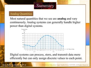
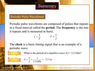
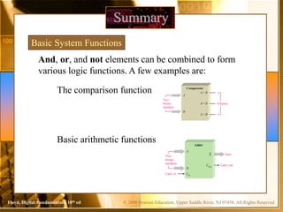
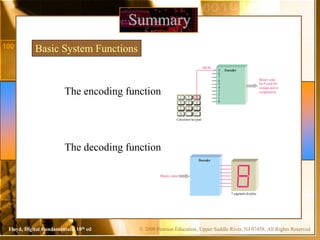
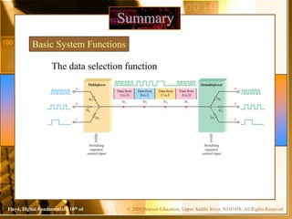
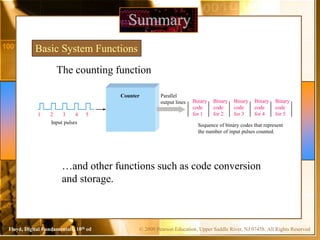
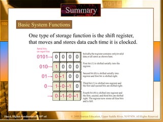
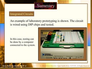
Week-1
University of Central Punjab
Faculty of Information Technology
CSCS2523-DIGITAL LOGIC DESIGN
© 2009 Pearson Education, Upper Saddle River, NJ 07458. All Rights Reserved
Floyd, Digital Fundamentals, 10th ed
Instructor Contact Details
Dr. Mujtaba Asad
PhD (Control Science & Engineering),
MS(EE), MS(CS), BS(TE)
• Course : CSCS2325- Digital Logic Design
• Credit Hours: 4(3+1)
• Email: mujtaba.asad@ucp.edu.pk
• Visiting Hours: Tba
2
© 2009 Pearson Education, Upper Saddle River, NJ 07458. All Rights Reserved
Floyd, Digital Fundamentals, 10th ed
How to Become Rich
:: Sura Ibrahim Ayat # 7
:: Sura Najam Ayat # 39
:: Sura Baqarah Ayat # 274
© 2009 Pearson Education, Upper Saddle River, NJ 07458. All Rights Reserved
Floyd, Digital Fundamentals, 10th ed
Course Objectives
This course provides a modern introduction to logic design and the
basic building blocks used in digital systems, in particular digital
computers. It starts with a discussion of combinational logic: logic
gates, minimization techniques, arithmetic circuits, and modern
logic devices such as field programmable logic gates. The second
part of the course deals with sequential circuits: flip-flops,
synthesis of sequential circuits, and case studies, including
counters, registers, and random-access memories. State machines
will then be discussed and illustrated through case studies of more
complex systems using programmable logic devices. Different
representations including truth table, logic gate, timing diagram,
switch representation, and state diagram will be discussed. Hands
on training is given on self-designed prototypes /Digital logic
Trainers and latest SPICE (Virtual Electronics Lab). Participants
will be able to make digital circuits on self designed
modules like Adder, ALU, MUX, DEMUX, Decoder, Encoder, RAM,
ROM, and Parity Checker and also display decimal digits on Seven
segment Indicators or State Monitors.
4
© 2009 Pearson Education, Upper Saddle River, NJ 07458. All Rights Reserved
Floyd, Digital Fundamentals, 10th ed
Text Books
1. Digital Fundamentals by Floyd 11th edition
2. Digital Logic and Computer Design by M. Morris Mano 3rd Edition
© 2009 Pearson Education, Upper Saddle River, NJ 07458. All Rights Reserved
Floyd, Digital Fundamentals, 10th ed
Most natural quantities that we see are analog and vary
continuously. Analog systems can generally handle higher
power than digital systems.
Summary
Digital systems can process, store, and transmit data more
efficiently but can only assign discrete values to each point.
Analog Quantities
1
100
A .M.
95
90
85
80
75
2 3 4 5 6 7 8 9 10 11 12 1 2 3 4 5 6 7 8 9 10 11 12
P.M.
Temperature
(°F)
70
Time of day
© 2009 Pearson Education, Upper Saddle River, NJ 07458. All Rights Reserved
Floyd, Digital Fundamentals, 10th ed
Many systems use a mix of analog and digital electronics to
take advantage of each technology. A typical CD player
accepts digital data from the CD drive and converts it to an
analog signal for amplification.
Summary
Analog and Digital Systems
Digital data
CD drive
10110011101
Analog
reproduction
of musicaudio
signal
Speaker
Sound
waves
Digital-to-analog
converter
Linear amplifier
© 2009 Pearson Education, Upper Saddle River, NJ 07458. All Rights Reserved
Floyd, Digital Fundamentals, 10th ed
Digital electronics uses circuits that have two states, which
are represented by two different voltage levels called HIGH
and LOW. The voltages represent numbers in the binary
system.
Summary
Binary Digits and Logic Levels
In binary, a single number is
called a bit (for binary digit). A
bit can have the value of either
a 0 or a 1, depending on if the
voltage is HIGH or LOW.
HIGH
LOW
VH(max)
VH(min)
VL(max)
VL(min)
Invalid
© 2009 Pearson Education, Upper Saddle River, NJ 07458. All Rights Reserved
Floyd, Digital Fundamentals, 10th ed
Digital waveforms change between the LOW and HIGH
levels. A positive going pulse is one that goes from a
normally LOW logic level to a HIGH level and then back
again. Digital waveforms are made up of a series of pulses.
Summary
Digital Waveforms
Falling or
leading edge
(b) Negative–going pulse
HIGH
Rising or
trailing edge
LOW
(a) Positive–going pulse
HIGH
Rising or
leading edge
Falling or
trailing edge
LOW
t0
t1
t0
t1
© 2009 Pearson Education, Upper Saddle River, NJ 07458. All Rights Reserved
Floyd, Digital Fundamentals, 10th ed
Periodic pulse waveforms are composed of pulses that repeats
in a fixed interval called the period. The frequency is the rate
it repeats and is measured in hertz.
Summary
Periodic Pulse Waveforms
T
f
1

f
T
1

The clock is a basic timing signal that is an example of a
periodic wave.
What is the period of a repetitive wave if f = 3.2 GHz?



GHz
2
.
3
1
1
f
T 313 ps
© 2009 Pearson Education, Upper Saddle River, NJ 07458. All Rights Reserved
Floyd, Digital Fundamentals, 10th ed
Summary
Pulse Definitions
In addition to frequency and period, repetitive pulse waveforms
are described by the amplitude (A), pulse width (tW) and duty
cycle. Duty cycle is the ratio of tW to T.
Volts
Time
Amplitude (A)
Pulse
width
(tW)
Period, T
© 2009 Pearson Education, Upper Saddle River, NJ 07458. All Rights Reserved
Floyd, Digital Fundamentals, 10th ed
A timing diagram is used to show the relationship between
two or more digital waveforms,
Summary
Timing Diagrams
Clock
A
B
C
A diagram like this can be observed
directly on a logic analyzer.
© 2009 Pearson Education, Upper Saddle River, NJ 07458. All Rights Reserved
Floyd, Digital Fundamentals, 10th ed
Data can be transmitted by either serial transfer or parallel
transfer.
Summary
Serial and Parallel Data
Computer Modem
1 0 1 1 0 0 1 0
t0 t1 t2 t3 t4 t5 t6 t7
Computer Printer
0
t0 t1
1
0
0
1
1
0
1
© 2009 Pearson Education, Upper Saddle River, NJ 07458. All Rights Reserved
Floyd, Digital Fundamentals, 10th ed
Summary
Basic Logic Functions
True only if all input conditions
are true.
True only if one or more input
conditions are true.
Indicates the opposite condition.
© 2009 Pearson Education, Upper Saddle River, NJ 07458. All Rights Reserved
Floyd, Digital Fundamentals, 10th ed
Summary
Basic System Functions
And, or, and not elements can be combined to form
various logic functions. A few examples are:
The comparison function
Basic arithmetic functions Adder
Two
binary
numbers Carry out
A
B
Cout
Cin
Carry in
Sum
Σ
Two
binary
numbers
Outputs
A
B
A< B
A= B
A> B
Comparator
© 2009 Pearson Education, Upper Saddle River, NJ 07458. All Rights Reserved
Floyd, Digital Fundamentals, 10th ed
Summary
Basic System Functions
The encoding function
The decoding function
Decoder
Binary input
7-segment display
Encoder
9
8 9
4 5 6
1 2 3
0 . +/–
7
Calculator keypad
8
7
6
5
4
3
2
1
0
HIGH
Binary code
for 9 used for
storage and/or
computation
© 2009 Pearson Education, Upper Saddle River, NJ 07458. All Rights Reserved
Floyd, Digital Fundamentals, 10th ed
Summary
Basic System Functions
The data selection function
Multiplexer
A
Switching
sequence
control input
B
C
∆t2
∆t3
∆t1
∆t2
∆t3
∆t1
Demultiplexer
D
E
F
Data from
Ato D
Data from
Bto E
Data from
Cto F
Data from
Ato D
∆t1 ∆t2 ∆t3 ∆t1
Switching
sequence
control input
© 2009 Pearson Education, Upper Saddle River, NJ 07458. All Rights Reserved
Floyd, Digital Fundamentals, 10th ed
Summary
Basic System Functions
The counting function
…and other functions such as code conversion
and storage.
Input pulses
1
Counter Parallel
output lines Binary
code
for 1
Binary
code
for 2
Binary
code
for 3
Binary
code
for 4
Binary
code
for 5
Sequence of binary codes that represent
the number of input pulses counted.
2 3 4 5
© 2009 Pearson Education, Upper Saddle River, NJ 07458. All Rights Reserved
Floyd, Digital Fundamentals, 10th ed
Summary
Basic System Functions
One type of storage function is the shift register,
that moves and stores data each time it is clocked.
0 0 0 0
0101
Initially
,the register contains onlyinvalid
data or all zeros as shown here.
1 0 0 0
010
First bit (1) is shifted serially into the
register.
0 1 0 0
01
Second bit (0) is shifted serially into
register and first bit is shifted right.
1 0 1 0
0
Third bit (1) is shifted into register and
the first and second bits are shifted right.
0 1 0 1
Fourth bit (0) is shifted into register and
the first,second,and third bits are shifted
right.The register now stores all four bits
and is full.
Serial bits
on input line
© 2009 Pearson Education, Upper Saddle River, NJ 07458. All Rights Reserved
Floyd, Digital Fundamentals, 10th ed
Summary
Integrated Circuits
Plastic
case
Pins
Chip
Cutaway view of DIP (Dual-In-line Pins) chip:
The TTL series, available as DIPs are popular
for laboratory experiments with logic.
© 2009 Pearson Education, Upper Saddle River, NJ 07458. All Rights Reserved
Floyd, Digital Fundamentals, 10th ed
Summary
An example of laboratory prototyping is shown. The circuit
is wired using DIP chips and tested.
Integrated Circuits
In this case, testing can
be done by a computer
connected to the system.
DIP chips
© 2009 Pearson Education, Upper Saddle River, NJ 07458. All Rights Reserved
Floyd, Digital Fundamentals, 10th ed
Summary
Integrated Circuits
DIP chips and surface mount chips
Pin 1
Dual in-line package Small outline IC (SOIC)
© 2009 Pearson Education, Upper Saddle River, NJ 07458. All Rights Reserved
Floyd, Digital Fundamentals, 10th ed
Selected Key Terms
Analog
Digital
Binary
Bit
Pulse
Being continuous or having continuous values.
Related to digits or discrete quantities; having a set
of discrete values.
Having two values or states; describes a number
system that has a base of two and utilizes 1 and 0
as its digits.
A binary digit, which can be a 1 or a 0.
A sudden change from one level to another,
followed after a time, called the pulse width, by a
sudden change back to the original level.
© 2009 Pearson Education, Upper Saddle River, NJ 07458. All Rights Reserved
Floyd, Digital Fundamentals, 10th ed
Selected Key Terms
Clock
Gate
NOT
AND
OR
A basic timing signal in a digital system; a periodic
waveform used to synchronize actions.
A logic circuit that performs a basic logic
operations such as AND or OR.
A basic logic function that performs inversion.
A basic logic operation in which a true (HIGH)
output occurs only when all input conditions are
true (HIGH).
A basic logic operation in which a true (HIGH)
output occurs when when one or more of the input
conditions are true (HIGH).
© 2009 Pearson Education, Upper Saddle River, NJ 07458. All Rights Reserved
Floyd, Digital Fundamentals, 10th ed
Selected Key Terms
Fixed-function
logic
Programmable
logic
A category of digital integrated circuits having
functions that cannot be altered.
A category of digital integrated circuits capable of
being programmed to perform specified functions.
© 2009 Pearson Education, Upper Saddle River, NJ 07458. All Rights Reserved
Floyd, Digital Fundamentals, 10th ed
1. Compared to analog systems, digital systems
a. are less prone to noise
b. can represent an infinite number of values
c. can handle much higher power
d. all of the above
© 2008 Pearson Education
© 2009 Pearson Education, Upper Saddle River, NJ 07458. All Rights Reserved
Floyd, Digital Fundamentals, 10th ed
2. The number of values that can be assigned to a bit are
a. one
b. two
c. three
d. ten
© 2008 Pearson Education
© 2009 Pearson Education, Upper Saddle River, NJ 07458. All Rights Reserved
Floyd, Digital Fundamentals, 10th ed
3. The time measurement between the 50% point on the
leading edge of a pulse to the 50% point on the trailing edge
of the pulse is called the
a. rise time
b. fall time
c. period
d. pulse width
© 2008 Pearson Education
© 2009 Pearson Education, Upper Saddle River, NJ 07458. All Rights Reserved
Floyd, Digital Fundamentals, 10th ed
5. The reciprocal of the frequency of a clock signal is the
a. rise time
b. fall time
c. period
d. pulse width
© 2008 Pearson Education
© 2009 Pearson Education, Upper Saddle River, NJ 07458. All Rights Reserved
Floyd, Digital Fundamentals, 10th ed
6. If the period of a clock signal is 500 ps, the frequency is
a. 20 MHz
b. 200 MHz
c. 2 GHz
d. 20 GHz
© 2008 Pearson Education
© 2009 Pearson Education, Upper Saddle River, NJ 07458. All Rights Reserved
Floyd, Digital Fundamentals, 10th ed
7. AND, OR, and NOT gates can be used to form
a. storage devices
b. comparators
c. data selectors
d. all of the above
© 2008 Pearson Education
© 2009 Pearson Education, Upper Saddle River, NJ 07458. All Rights Reserved
Floyd, Digital Fundamentals, 10th ed
8. A shift register is an example of a
a. storage device
b. comparator
c. data selector
d. counter
© 2008 Pearson Education
© 2009 Pearson Education, Upper Saddle River, NJ 07458. All Rights Reserved
Floyd, Digital Fundamentals, 10th ed
9. A device that is used to switch one of several input lines to
a single output line is called a
a. comparator
b. decoder
c. counter
d. multiplexer
© 2008 Pearson Education
© 2009 Pearson Education, Upper Saddle River, NJ 07458. All Rights Reserved
Floyd, Digital Fundamentals, 10th ed
10. For most digital work, an oscilloscope should be coupled
to the signal using
a. ac coupling
b. dc coupling
c. GND coupling
d. none of the above
© 2008 Pearson Education
© 2009 Pearson Education, Upper Saddle River, NJ 07458. All Rights Reserved
Floyd, Digital Fundamentals, 10th ed
Answers:
1. a
2. b
3. d
4. b
5. c
6. c
7. d
8. a
9. d
10. b

Week 1 Lecture.ppt

  • 1.
    Week-1 University of CentralPunjab Faculty of Information Technology CSCS2523-DIGITAL LOGIC DESIGN
  • 2.
    © 2009 PearsonEducation, Upper Saddle River, NJ 07458. All Rights Reserved Floyd, Digital Fundamentals, 10th ed Instructor Contact Details Dr. Mujtaba Asad PhD (Control Science & Engineering), MS(EE), MS(CS), BS(TE) • Course : CSCS2325- Digital Logic Design • Credit Hours: 4(3+1) • Email: mujtaba.asad@ucp.edu.pk • Visiting Hours: Tba 2
  • 3.
    © 2009 PearsonEducation, Upper Saddle River, NJ 07458. All Rights Reserved Floyd, Digital Fundamentals, 10th ed How to Become Rich :: Sura Ibrahim Ayat # 7 :: Sura Najam Ayat # 39 :: Sura Baqarah Ayat # 274
  • 4.
    © 2009 PearsonEducation, Upper Saddle River, NJ 07458. All Rights Reserved Floyd, Digital Fundamentals, 10th ed Course Objectives This course provides a modern introduction to logic design and the basic building blocks used in digital systems, in particular digital computers. It starts with a discussion of combinational logic: logic gates, minimization techniques, arithmetic circuits, and modern logic devices such as field programmable logic gates. The second part of the course deals with sequential circuits: flip-flops, synthesis of sequential circuits, and case studies, including counters, registers, and random-access memories. State machines will then be discussed and illustrated through case studies of more complex systems using programmable logic devices. Different representations including truth table, logic gate, timing diagram, switch representation, and state diagram will be discussed. Hands on training is given on self-designed prototypes /Digital logic Trainers and latest SPICE (Virtual Electronics Lab). Participants will be able to make digital circuits on self designed modules like Adder, ALU, MUX, DEMUX, Decoder, Encoder, RAM, ROM, and Parity Checker and also display decimal digits on Seven segment Indicators or State Monitors. 4
  • 5.
    © 2009 PearsonEducation, Upper Saddle River, NJ 07458. All Rights Reserved Floyd, Digital Fundamentals, 10th ed Text Books 1. Digital Fundamentals by Floyd 11th edition 2. Digital Logic and Computer Design by M. Morris Mano 3rd Edition
  • 6.
    © 2009 PearsonEducation, Upper Saddle River, NJ 07458. All Rights Reserved Floyd, Digital Fundamentals, 10th ed Most natural quantities that we see are analog and vary continuously. Analog systems can generally handle higher power than digital systems. Summary Digital systems can process, store, and transmit data more efficiently but can only assign discrete values to each point. Analog Quantities 1 100 A .M. 95 90 85 80 75 2 3 4 5 6 7 8 9 10 11 12 1 2 3 4 5 6 7 8 9 10 11 12 P.M. Temperature (°F) 70 Time of day
  • 7.
    © 2009 PearsonEducation, Upper Saddle River, NJ 07458. All Rights Reserved Floyd, Digital Fundamentals, 10th ed Many systems use a mix of analog and digital electronics to take advantage of each technology. A typical CD player accepts digital data from the CD drive and converts it to an analog signal for amplification. Summary Analog and Digital Systems Digital data CD drive 10110011101 Analog reproduction of musicaudio signal Speaker Sound waves Digital-to-analog converter Linear amplifier
  • 8.
    © 2009 PearsonEducation, Upper Saddle River, NJ 07458. All Rights Reserved Floyd, Digital Fundamentals, 10th ed Digital electronics uses circuits that have two states, which are represented by two different voltage levels called HIGH and LOW. The voltages represent numbers in the binary system. Summary Binary Digits and Logic Levels In binary, a single number is called a bit (for binary digit). A bit can have the value of either a 0 or a 1, depending on if the voltage is HIGH or LOW. HIGH LOW VH(max) VH(min) VL(max) VL(min) Invalid
  • 9.
    © 2009 PearsonEducation, Upper Saddle River, NJ 07458. All Rights Reserved Floyd, Digital Fundamentals, 10th ed Digital waveforms change between the LOW and HIGH levels. A positive going pulse is one that goes from a normally LOW logic level to a HIGH level and then back again. Digital waveforms are made up of a series of pulses. Summary Digital Waveforms Falling or leading edge (b) Negative–going pulse HIGH Rising or trailing edge LOW (a) Positive–going pulse HIGH Rising or leading edge Falling or trailing edge LOW t0 t1 t0 t1
  • 10.
    © 2009 PearsonEducation, Upper Saddle River, NJ 07458. All Rights Reserved Floyd, Digital Fundamentals, 10th ed Periodic pulse waveforms are composed of pulses that repeats in a fixed interval called the period. The frequency is the rate it repeats and is measured in hertz. Summary Periodic Pulse Waveforms T f 1  f T 1  The clock is a basic timing signal that is an example of a periodic wave. What is the period of a repetitive wave if f = 3.2 GHz?    GHz 2 . 3 1 1 f T 313 ps
  • 11.
    © 2009 PearsonEducation, Upper Saddle River, NJ 07458. All Rights Reserved Floyd, Digital Fundamentals, 10th ed Summary Pulse Definitions In addition to frequency and period, repetitive pulse waveforms are described by the amplitude (A), pulse width (tW) and duty cycle. Duty cycle is the ratio of tW to T. Volts Time Amplitude (A) Pulse width (tW) Period, T
  • 12.
    © 2009 PearsonEducation, Upper Saddle River, NJ 07458. All Rights Reserved Floyd, Digital Fundamentals, 10th ed A timing diagram is used to show the relationship between two or more digital waveforms, Summary Timing Diagrams Clock A B C A diagram like this can be observed directly on a logic analyzer.
  • 13.
    © 2009 PearsonEducation, Upper Saddle River, NJ 07458. All Rights Reserved Floyd, Digital Fundamentals, 10th ed Data can be transmitted by either serial transfer or parallel transfer. Summary Serial and Parallel Data Computer Modem 1 0 1 1 0 0 1 0 t0 t1 t2 t3 t4 t5 t6 t7 Computer Printer 0 t0 t1 1 0 0 1 1 0 1
  • 14.
    © 2009 PearsonEducation, Upper Saddle River, NJ 07458. All Rights Reserved Floyd, Digital Fundamentals, 10th ed Summary Basic Logic Functions True only if all input conditions are true. True only if one or more input conditions are true. Indicates the opposite condition.
  • 15.
    © 2009 PearsonEducation, Upper Saddle River, NJ 07458. All Rights Reserved Floyd, Digital Fundamentals, 10th ed Summary Basic System Functions And, or, and not elements can be combined to form various logic functions. A few examples are: The comparison function Basic arithmetic functions Adder Two binary numbers Carry out A B Cout Cin Carry in Sum Σ Two binary numbers Outputs A B A< B A= B A> B Comparator
  • 16.
    © 2009 PearsonEducation, Upper Saddle River, NJ 07458. All Rights Reserved Floyd, Digital Fundamentals, 10th ed Summary Basic System Functions The encoding function The decoding function Decoder Binary input 7-segment display Encoder 9 8 9 4 5 6 1 2 3 0 . +/– 7 Calculator keypad 8 7 6 5 4 3 2 1 0 HIGH Binary code for 9 used for storage and/or computation
  • 17.
    © 2009 PearsonEducation, Upper Saddle River, NJ 07458. All Rights Reserved Floyd, Digital Fundamentals, 10th ed Summary Basic System Functions The data selection function Multiplexer A Switching sequence control input B C ∆t2 ∆t3 ∆t1 ∆t2 ∆t3 ∆t1 Demultiplexer D E F Data from Ato D Data from Bto E Data from Cto F Data from Ato D ∆t1 ∆t2 ∆t3 ∆t1 Switching sequence control input
  • 18.
    © 2009 PearsonEducation, Upper Saddle River, NJ 07458. All Rights Reserved Floyd, Digital Fundamentals, 10th ed Summary Basic System Functions The counting function …and other functions such as code conversion and storage. Input pulses 1 Counter Parallel output lines Binary code for 1 Binary code for 2 Binary code for 3 Binary code for 4 Binary code for 5 Sequence of binary codes that represent the number of input pulses counted. 2 3 4 5
  • 19.
    © 2009 PearsonEducation, Upper Saddle River, NJ 07458. All Rights Reserved Floyd, Digital Fundamentals, 10th ed Summary Basic System Functions One type of storage function is the shift register, that moves and stores data each time it is clocked. 0 0 0 0 0101 Initially ,the register contains onlyinvalid data or all zeros as shown here. 1 0 0 0 010 First bit (1) is shifted serially into the register. 0 1 0 0 01 Second bit (0) is shifted serially into register and first bit is shifted right. 1 0 1 0 0 Third bit (1) is shifted into register and the first and second bits are shifted right. 0 1 0 1 Fourth bit (0) is shifted into register and the first,second,and third bits are shifted right.The register now stores all four bits and is full. Serial bits on input line
  • 20.
    © 2009 PearsonEducation, Upper Saddle River, NJ 07458. All Rights Reserved Floyd, Digital Fundamentals, 10th ed Summary Integrated Circuits Plastic case Pins Chip Cutaway view of DIP (Dual-In-line Pins) chip: The TTL series, available as DIPs are popular for laboratory experiments with logic.
  • 21.
    © 2009 PearsonEducation, Upper Saddle River, NJ 07458. All Rights Reserved Floyd, Digital Fundamentals, 10th ed Summary An example of laboratory prototyping is shown. The circuit is wired using DIP chips and tested. Integrated Circuits In this case, testing can be done by a computer connected to the system. DIP chips
  • 22.
    © 2009 PearsonEducation, Upper Saddle River, NJ 07458. All Rights Reserved Floyd, Digital Fundamentals, 10th ed Summary Integrated Circuits DIP chips and surface mount chips Pin 1 Dual in-line package Small outline IC (SOIC)
  • 23.
    © 2009 PearsonEducation, Upper Saddle River, NJ 07458. All Rights Reserved Floyd, Digital Fundamentals, 10th ed Selected Key Terms Analog Digital Binary Bit Pulse Being continuous or having continuous values. Related to digits or discrete quantities; having a set of discrete values. Having two values or states; describes a number system that has a base of two and utilizes 1 and 0 as its digits. A binary digit, which can be a 1 or a 0. A sudden change from one level to another, followed after a time, called the pulse width, by a sudden change back to the original level.
  • 24.
    © 2009 PearsonEducation, Upper Saddle River, NJ 07458. All Rights Reserved Floyd, Digital Fundamentals, 10th ed Selected Key Terms Clock Gate NOT AND OR A basic timing signal in a digital system; a periodic waveform used to synchronize actions. A logic circuit that performs a basic logic operations such as AND or OR. A basic logic function that performs inversion. A basic logic operation in which a true (HIGH) output occurs only when all input conditions are true (HIGH). A basic logic operation in which a true (HIGH) output occurs when when one or more of the input conditions are true (HIGH).
  • 25.
    © 2009 PearsonEducation, Upper Saddle River, NJ 07458. All Rights Reserved Floyd, Digital Fundamentals, 10th ed Selected Key Terms Fixed-function logic Programmable logic A category of digital integrated circuits having functions that cannot be altered. A category of digital integrated circuits capable of being programmed to perform specified functions.
  • 26.
    © 2009 PearsonEducation, Upper Saddle River, NJ 07458. All Rights Reserved Floyd, Digital Fundamentals, 10th ed 1. Compared to analog systems, digital systems a. are less prone to noise b. can represent an infinite number of values c. can handle much higher power d. all of the above © 2008 Pearson Education
  • 27.
    © 2009 PearsonEducation, Upper Saddle River, NJ 07458. All Rights Reserved Floyd, Digital Fundamentals, 10th ed 2. The number of values that can be assigned to a bit are a. one b. two c. three d. ten © 2008 Pearson Education
  • 28.
    © 2009 PearsonEducation, Upper Saddle River, NJ 07458. All Rights Reserved Floyd, Digital Fundamentals, 10th ed 3. The time measurement between the 50% point on the leading edge of a pulse to the 50% point on the trailing edge of the pulse is called the a. rise time b. fall time c. period d. pulse width © 2008 Pearson Education
  • 29.
    © 2009 PearsonEducation, Upper Saddle River, NJ 07458. All Rights Reserved Floyd, Digital Fundamentals, 10th ed 5. The reciprocal of the frequency of a clock signal is the a. rise time b. fall time c. period d. pulse width © 2008 Pearson Education
  • 30.
    © 2009 PearsonEducation, Upper Saddle River, NJ 07458. All Rights Reserved Floyd, Digital Fundamentals, 10th ed 6. If the period of a clock signal is 500 ps, the frequency is a. 20 MHz b. 200 MHz c. 2 GHz d. 20 GHz © 2008 Pearson Education
  • 31.
    © 2009 PearsonEducation, Upper Saddle River, NJ 07458. All Rights Reserved Floyd, Digital Fundamentals, 10th ed 7. AND, OR, and NOT gates can be used to form a. storage devices b. comparators c. data selectors d. all of the above © 2008 Pearson Education
  • 32.
    © 2009 PearsonEducation, Upper Saddle River, NJ 07458. All Rights Reserved Floyd, Digital Fundamentals, 10th ed 8. A shift register is an example of a a. storage device b. comparator c. data selector d. counter © 2008 Pearson Education
  • 33.
    © 2009 PearsonEducation, Upper Saddle River, NJ 07458. All Rights Reserved Floyd, Digital Fundamentals, 10th ed 9. A device that is used to switch one of several input lines to a single output line is called a a. comparator b. decoder c. counter d. multiplexer © 2008 Pearson Education
  • 34.
    © 2009 PearsonEducation, Upper Saddle River, NJ 07458. All Rights Reserved Floyd, Digital Fundamentals, 10th ed 10. For most digital work, an oscilloscope should be coupled to the signal using a. ac coupling b. dc coupling c. GND coupling d. none of the above © 2008 Pearson Education
  • 35.
    © 2009 PearsonEducation, Upper Saddle River, NJ 07458. All Rights Reserved Floyd, Digital Fundamentals, 10th ed Answers: 1. a 2. b 3. d 4. b 5. c 6. c 7. d 8. a 9. d 10. b