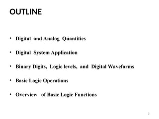
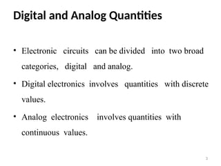
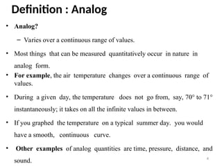
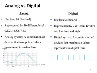
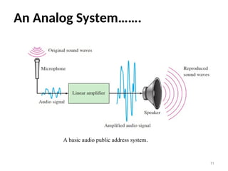
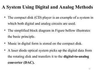
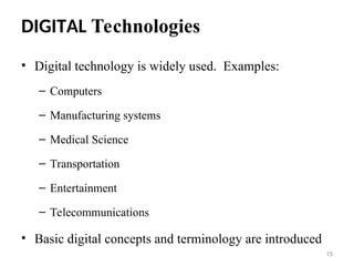
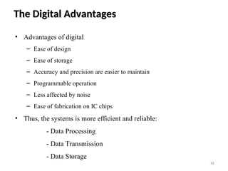
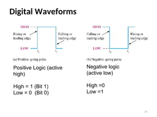
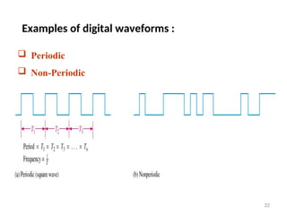
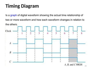
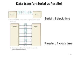
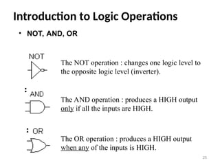
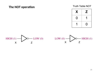
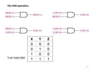
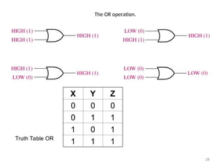
SCHOOLOF ELECTRICAL AND COMPUTER
ENGINEERING
Digital Logic Design
Chapter 1
Chapter 1
Digital Concepts
OUTLINE
• Digital and Analog Quantities
• Digital System Application
• Binary Digits, Logic levels, and Digital Waveforms
• Basic Logic Operations
• Overview of Basic Logic Functions
2
Digital and Analog Quantities
• Electronic circuits can be divided into two broad
categories, digital and analog.
• Digital electronics involves quantities with discrete
values.
• Analog electronics involves quantities with
continuous values.
3
Definition : Analog
• Analog?
– Varies over a continuous range of values.
• Most things that can be measured quantitatively occur in nature in
analog form.
• For example, the air temperature changes over a continuous range of
values.
• During a given day, the temperature does not go from, say, 70° to 71°
instantaneously; it takes on all the infinite values in between.
• If you graphed the temperature on a typical summer day. you would
have a smooth, continuous curve.
• Other examples of analog quantities are time, pressure, distance, and
sound. 4
Analog
5
Graph of an analog quantity (temperature versus time)
• Digital?
– A discrete set of values.
– Varies in discrete (separate) steps.
• Rather than graphing the temperature on a continuous basis,
suppose you just take a temperature reading every hour.
• Now you have sampled values representing the temperature at
discrete points in time (every hour) over a 24-hour period, as
indicated in Figure bellow.
6
Definition : Digital
Digital
7
Sampled-value representation (quantization) of the analog quantity in Figure above.
Each value represented by a dot can be digitized by representing it as a digital code that
consists of a series of 1 s and Os.
Analog vs Digital
Analog
• Use base 10 (decimal)
• Represented by 10 different level :
0,1,2,3,4,5,6,7,8,9
• Analog system: A combination of
devices that manipulate values
represented in analog form
8
Digital
 Use base 2 (binary)
 Represented by 2 different level: 0
and 1 or low and high.
 Digital system: A combination of
devices that manipulate values
represented in digital form.
An Analog System
• A public address system, used to amplify sound so that it can
be heard by a large audience, is one simple example of an
application of analog electronics.
• The basic diagram in Figure bellow illustrates that sound
waves, which are analog in nature, are picked up by a
microphone and converted to a small analog voltage called the
audio signal. 9
An Analog System…..
• This voltage varies continuously as the volume and
frequency of the sound changes and is applied to the input of
a linear amplifier.
• The output of the amplifier, which is an increased
reproduction of input voltage, goes to the speaker(s).
• The speaker changes the amplified audio signal back to
sound waves that have a much greater volume than the
original sound waves picked up by the microphone. 10
An Analog System…….
11
A basic audio public address system.
A System Using Digital and Analog Methods
• The compact disk (CD) player is an example of a system in
which both digital and analog circuits are used.
• The simplified block diagram in Figure bellow illustrates
the basic principle.
• Music in digital form is stored on the compact disk.
• A laser diode optical system picks up the digital data from
the rotating disk and transfers it to the digital-to-analog
converter (DAC).
12
A System Using Digital and Analog Methods…..
• The DAC changes the digital data into an analog signal that is
an electrical reproduction of the original music.
• This signal is amplified and sent to the speaker for you to
enjoy.
• When the music was originally recorded on the CD, a process,
essentially the reverse of the one described here, using an
analog-to-digital converter (ADC) was used.
13
A System Using Digital and Analog Methods…..
14
Basic block diagram of a CD player. Only one channel is shown.
DIGITAL Technologies
• Digital technology is widely used. Examples:
– Computers
– Manufacturing systems
– Medical Science
– Transportation
– Entertainment
– Telecommunications
• Basic digital concepts and terminology are introduced
15
The Digital Advantages
• Advantages of digital
– Ease of design
– Ease of storage
– Accuracy and precision are easier to maintain
– Programmable operation
– Less affected by noise
– Ease of fabrication on IC chips
• Thus, the systems is more efficient and reliable:
- Data Processing
- Data Transmission
- Data Storage
16
Binary digit logic level and digital waveform
• Digital electronics involves circuits and systems in which there are
only two possible states.
• These states are represented by two different voltage levels: A
HIGH and a LOW.
• In digital systems such as computers, combinations of the two
states, called codes, are used to represent numbers, symbols,
alphabetic characters, and other types of information.
• The two-state number system is called binary, and its two digits
are 0 and 1.
• A binary digit is called a bit. 17
Binary Digits
• Each of the two digits in the binary system, 1 and 0, is called a bit,
which is a contraction of the words binary digit.
• In digital circuits, two different voltage levels are used to represent
the two bits.
• Generally, 1 is represented by the higher voltage, which we will
refer to as a HIGH, and a 0 is represented by the lower voltage
level, which we will refer to as a LOW. This is called positive logic.
– HIGH _ 1 and LOW _ 0
• Another system in which a 1 is represented by a LOW and a 0 is
represented by a HIGH is called negative logic.
• Groups of bits (combinations of 1s and 0s), called codes, are used to
represent numbers, letters, symbols, instructions, and anything else
required in a given application.
18
Logic Levels
• The voltages used to represent a 1 and a 0 are called logic
levels.
• Ideally, one voltage level represents a HIGH and another
voltage level represents a LOW.
• In a practical digital circuit, however, a HIGH can be any
voltage between a specified minimum value and a specified
maximum value.
19
Binary Digits = Bit
20
Bit 1 : 2 – 5V(high)
Bit 0 : 0 – 0.8V(low)
Undefined : 0.8 – 2V
0V
0.8V
2.0V
5.0V
Digital Waveforms
21
Positive Logic (active
high)
High = 1 (Bit 1)
Low = 0 (Bit 0)
Negative logic
(active low)
High =0
Low =1
Examples of digital waveforms :
22
 Periodic
 Non-Periodic
Timing Diagram
23
Is a graph of digital waveform showing the actual time relationship of
two or more waveform and how each waveform changes in relation to
the others.
Data transfer: Serial vs Parallel
24
Serial : 8 clock time
Parallel : 1 clock time
Introduction to Logic Operations
25
The NOT operation : changes one logic level to
the opposite logic level (inverter).
The AND operation : produces a HIGH output
only if all the inputs are HIGH.
The OR operation : produces a HIGH output
when any of the inputs is HIGH.
• NOT, AND, OR
The NOT operation
X Z
0 1
1 0
26
X Z
Truth Table NOT
X Z
The AND operation.
27
X Y Z
0 0 0
0 1 0
1 0 0
1 1 1
Truth Table AND
The OR operation.
28
X Y Z
0 0 0
0 1 1
1 0 1
1 1 1
Truth Table OR
Overview of Logic Functions
29
• Basic Logic Functions
• Comparison Function
• Arithmetic Functions
• Code conversion function
• Encoding function
• Decoding function
• Data selection function
• Data storage function
• Counting function
The Comparison Function
30
The Arithmetic Functions
• Adder
• Substracter
• Multiplier
• Division
31
The Code conversion function
• A code is a set of bits arranged in a unique pattern
and used to represent specified information.
• Examples : BCD, ASCII
• Covered detail in other Chapter .
32
End
End
Q???
Q???
33

capte1111111111111111111111111111r 1.ppt

  • 1.
    SCHOOLOF ELECTRICAL ANDCOMPUTER ENGINEERING Digital Logic Design Chapter 1 Chapter 1 Digital Concepts
  • 2.
    OUTLINE • Digital andAnalog Quantities • Digital System Application • Binary Digits, Logic levels, and Digital Waveforms • Basic Logic Operations • Overview of Basic Logic Functions 2
  • 3.
    Digital and AnalogQuantities • Electronic circuits can be divided into two broad categories, digital and analog. • Digital electronics involves quantities with discrete values. • Analog electronics involves quantities with continuous values. 3
  • 4.
    Definition : Analog •Analog? – Varies over a continuous range of values. • Most things that can be measured quantitatively occur in nature in analog form. • For example, the air temperature changes over a continuous range of values. • During a given day, the temperature does not go from, say, 70° to 71° instantaneously; it takes on all the infinite values in between. • If you graphed the temperature on a typical summer day. you would have a smooth, continuous curve. • Other examples of analog quantities are time, pressure, distance, and sound. 4
  • 5.
    Analog 5 Graph of ananalog quantity (temperature versus time)
  • 6.
    • Digital? – Adiscrete set of values. – Varies in discrete (separate) steps. • Rather than graphing the temperature on a continuous basis, suppose you just take a temperature reading every hour. • Now you have sampled values representing the temperature at discrete points in time (every hour) over a 24-hour period, as indicated in Figure bellow. 6 Definition : Digital
  • 7.
    Digital 7 Sampled-value representation (quantization)of the analog quantity in Figure above. Each value represented by a dot can be digitized by representing it as a digital code that consists of a series of 1 s and Os.
  • 8.
    Analog vs Digital Analog •Use base 10 (decimal) • Represented by 10 different level : 0,1,2,3,4,5,6,7,8,9 • Analog system: A combination of devices that manipulate values represented in analog form 8 Digital  Use base 2 (binary)  Represented by 2 different level: 0 and 1 or low and high.  Digital system: A combination of devices that manipulate values represented in digital form.
  • 9.
    An Analog System •A public address system, used to amplify sound so that it can be heard by a large audience, is one simple example of an application of analog electronics. • The basic diagram in Figure bellow illustrates that sound waves, which are analog in nature, are picked up by a microphone and converted to a small analog voltage called the audio signal. 9
  • 10.
    An Analog System….. •This voltage varies continuously as the volume and frequency of the sound changes and is applied to the input of a linear amplifier. • The output of the amplifier, which is an increased reproduction of input voltage, goes to the speaker(s). • The speaker changes the amplified audio signal back to sound waves that have a much greater volume than the original sound waves picked up by the microphone. 10
  • 11.
    An Analog System……. 11 Abasic audio public address system.
  • 12.
    A System UsingDigital and Analog Methods • The compact disk (CD) player is an example of a system in which both digital and analog circuits are used. • The simplified block diagram in Figure bellow illustrates the basic principle. • Music in digital form is stored on the compact disk. • A laser diode optical system picks up the digital data from the rotating disk and transfers it to the digital-to-analog converter (DAC). 12
  • 13.
    A System UsingDigital and Analog Methods….. • The DAC changes the digital data into an analog signal that is an electrical reproduction of the original music. • This signal is amplified and sent to the speaker for you to enjoy. • When the music was originally recorded on the CD, a process, essentially the reverse of the one described here, using an analog-to-digital converter (ADC) was used. 13
  • 14.
    A System UsingDigital and Analog Methods….. 14 Basic block diagram of a CD player. Only one channel is shown.
  • 15.
    DIGITAL Technologies • Digitaltechnology is widely used. Examples: – Computers – Manufacturing systems – Medical Science – Transportation – Entertainment – Telecommunications • Basic digital concepts and terminology are introduced 15
  • 16.
    The Digital Advantages TheDigital Advantages • Advantages of digital – Ease of design – Ease of storage – Accuracy and precision are easier to maintain – Programmable operation – Less affected by noise – Ease of fabrication on IC chips • Thus, the systems is more efficient and reliable: - Data Processing - Data Transmission - Data Storage 16
  • 17.
    Binary digit logiclevel and digital waveform • Digital electronics involves circuits and systems in which there are only two possible states. • These states are represented by two different voltage levels: A HIGH and a LOW. • In digital systems such as computers, combinations of the two states, called codes, are used to represent numbers, symbols, alphabetic characters, and other types of information. • The two-state number system is called binary, and its two digits are 0 and 1. • A binary digit is called a bit. 17
  • 18.
    Binary Digits • Eachof the two digits in the binary system, 1 and 0, is called a bit, which is a contraction of the words binary digit. • In digital circuits, two different voltage levels are used to represent the two bits. • Generally, 1 is represented by the higher voltage, which we will refer to as a HIGH, and a 0 is represented by the lower voltage level, which we will refer to as a LOW. This is called positive logic. – HIGH _ 1 and LOW _ 0 • Another system in which a 1 is represented by a LOW and a 0 is represented by a HIGH is called negative logic. • Groups of bits (combinations of 1s and 0s), called codes, are used to represent numbers, letters, symbols, instructions, and anything else required in a given application. 18
  • 19.
    Logic Levels • Thevoltages used to represent a 1 and a 0 are called logic levels. • Ideally, one voltage level represents a HIGH and another voltage level represents a LOW. • In a practical digital circuit, however, a HIGH can be any voltage between a specified minimum value and a specified maximum value. 19
  • 20.
    Binary Digits =Bit 20 Bit 1 : 2 – 5V(high) Bit 0 : 0 – 0.8V(low) Undefined : 0.8 – 2V 0V 0.8V 2.0V 5.0V
  • 21.
    Digital Waveforms 21 Positive Logic(active high) High = 1 (Bit 1) Low = 0 (Bit 0) Negative logic (active low) High =0 Low =1
  • 22.
    Examples of digitalwaveforms : 22  Periodic  Non-Periodic
  • 23.
    Timing Diagram 23 Is agraph of digital waveform showing the actual time relationship of two or more waveform and how each waveform changes in relation to the others.
  • 24.
    Data transfer: Serialvs Parallel 24 Serial : 8 clock time Parallel : 1 clock time
  • 25.
    Introduction to LogicOperations 25 The NOT operation : changes one logic level to the opposite logic level (inverter). The AND operation : produces a HIGH output only if all the inputs are HIGH. The OR operation : produces a HIGH output when any of the inputs is HIGH. • NOT, AND, OR
  • 26.
    The NOT operation XZ 0 1 1 0 26 X Z Truth Table NOT X Z
  • 27.
    The AND operation. 27 XY Z 0 0 0 0 1 0 1 0 0 1 1 1 Truth Table AND
  • 28.
    The OR operation. 28 XY Z 0 0 0 0 1 1 1 0 1 1 1 1 Truth Table OR
  • 29.
    Overview of LogicFunctions 29 • Basic Logic Functions • Comparison Function • Arithmetic Functions • Code conversion function • Encoding function • Decoding function • Data selection function • Data storage function • Counting function
  • 30.
  • 31.
    The Arithmetic Functions •Adder • Substracter • Multiplier • Division 31
  • 32.
    The Code conversionfunction • A code is a set of bits arranged in a unique pattern and used to represent specified information. • Examples : BCD, ASCII • Covered detail in other Chapter . 32
  • 33.