Download to read offline


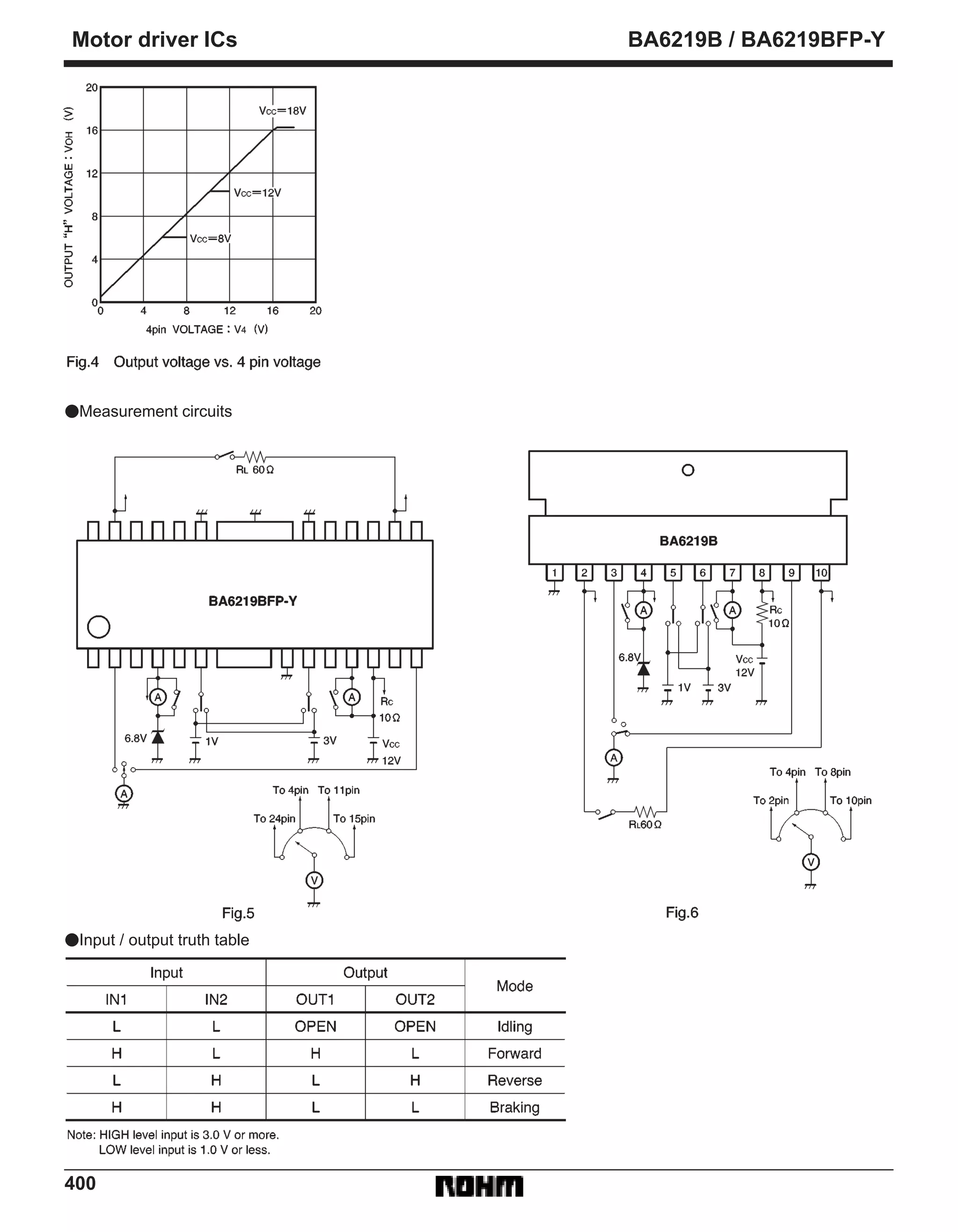
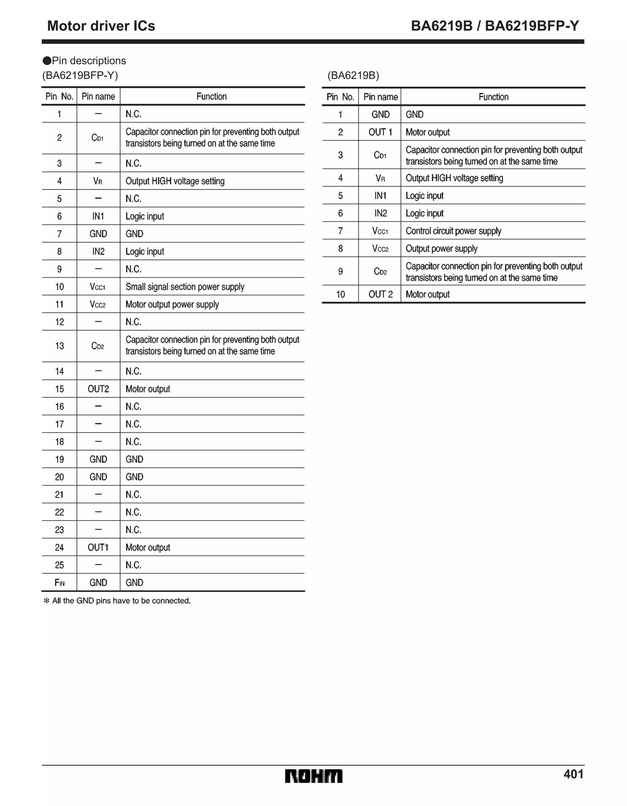
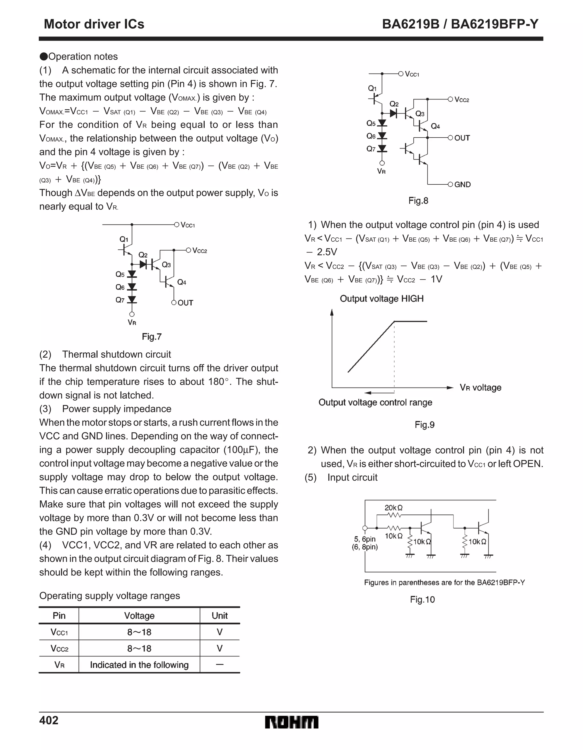


The BA6219B and BA6219BFP-Y are reversible motor driver ICs suitable for brush motors. They have two logic inputs that allow four output modes: forward, reverse, idling, and braking. The motor speed can be set arbitrarily by controlling the voltage applied to the motor. Key features include a large output current, thermal shutdown protection, and pins to set the output voltage. Application examples are provided.