Downloaded 895 times

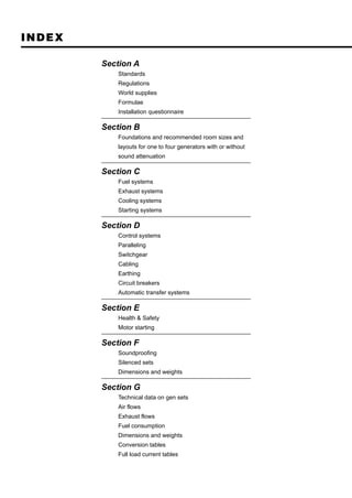

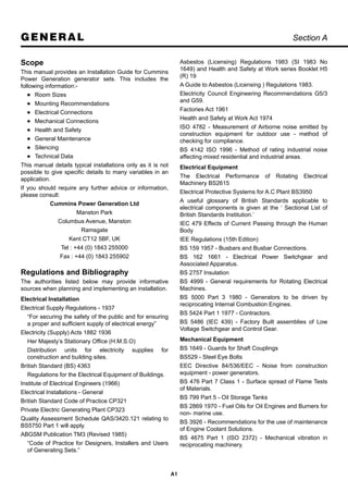


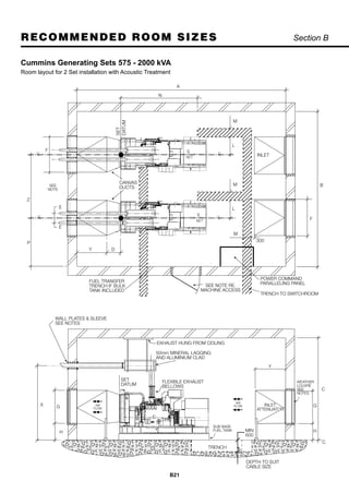
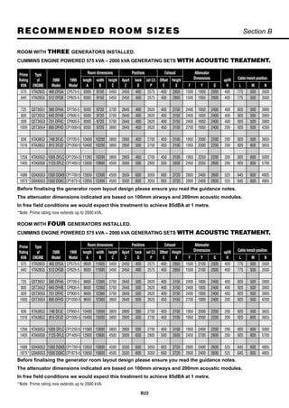
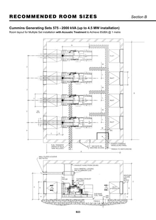
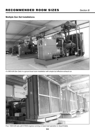


This document provides an application and installation guide for Cummins generator sets. It includes sections on standards, regulations, recommended room sizes and layouts, fuel systems, exhaust systems, cooling systems, starting systems, control systems, soundproofing, dimensions, weights, and technical data. The guide details considerations for planning, installing, and commissioning generator set installations according to relevant regulations and safety standards.