
Recommended
More Related Content
What's hot
What's hot (20)
Similar to Different types of rail failures
Similar to Different types of rail failures (20)
More from Sunil Kumar Meena
More from Sunil Kumar Meena (9)
Recently uploaded
Recently uploaded (20)
Different types of rail failures
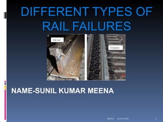
- 1. NAME-SUNIL KUMAR MEENA DIFFERENT TYPES OF RAIL FAILURES 15-10-2020 654/17 1
- 2. Different types of Rail failures CrushedHead Split Head TransverseFissure Horizontal Fissure Square & Angularbreaks 15-10-2020 654/17 2
- 3. Crushed Head Head getscrushed ,metalflows on theheadof rails Defects in manufacture, flat spots on wheels, slipping of wheels , weaksupport attherailend Skidding causes flat spots, loose fish bolts causes weak supports atthe ends 15-10-2020 654/17 3
- 5. Split Head Head is split into two parts Formed due to cavity during manufacture or shrinkage of metal 15-10-2020 654/17 5
- 7. Transverse Fissures Fissure or hole in the head occurs due to the poor manufacturing orexcessive straining. Poor manufacture,excessive straining Very Dangerous, railbreaks without any sign 15-10-2020 654/17 7
- 9. Horizontal Fissures Horizontal fissures occurs in head and web of the rail. Itdevelops and keeps on increasing. It occurs due to insufficient ballast and worn fish plates. 15-10-2020 654/17 9
- 11. Square andAngular Breaks Rails breaks either in vertical plane or angular plane. 15-10-2020 654/17 11
- 13. Material Required Per Km length of MG Track Rails Length of one rail =12m Density= 37.2kg/m or(75lb/yd) No. of rails per km=2*(1000/length of one rail) =2*(1000/12)=167 Weight of rail per km=(density*length 0f one rail*no. of rails) =37.2*12*167=74548.8kg 15-10-2020 654/17 13
- 14. Sleepers and Fish Plates No. of sleepers per km=0.5*(no. of rails per km*(M+X)) =0.5*167*(12+5)=1420 where M=length of one rail X=density factor No. of fish plates per Km=2*No. of rails per km =2*167=334 No. of fish bolts per Km=4*no. of rails per km =4*167=668 15-10-2020 654/17 14
- 15. Bearing Plates and Ballast No. of bearing plates per km=2*No. of sleepers per km =2*1420=2840 Bearing Fasteners= No. of sleepers per km*12 =1420*12=17040 Quantity of Ballast=The quantity of ballast required per m for metre gauge is 0.71cubic metre. 15-10-2020 654/17 15
- 16. Different Types of Rail Wear Wearof rails on the top (vertical wear) Wear of rails at the end of the rails (battering of the rail ends) Wearof rails on the side of head of rail (lateral wear) 15-10-2020 654/17 16
- 17. Wear of Rails on the Top The metal from the top of rail flows and forms projections. These projections are known as burrs. Rails worn out on the top due to abrasion of the rolling wheels over them. 15-10-2020 654/17 17
- 18. Wear of Rails at the End of the Rails Takes place at the end of the rails. Much greater than the top of rails. Causes battering i.e., wear of end. Fish plates become loose. 15-10-2020 654/17 18
- 20. Wear of Rails on the Side of Head Rails Most destructive type of wear. Occurs mainly at the curves. 15-10-2020 654/17 20
- 21. Method of Measurement of Creep Creep can be measured with the help of a device called creep indicator. It consists of two creepposts, which aregenerally rail pieces that are driven at 1-km intervals on either side of the track. For the purpose of easy measurement, their top level is generally at the same level as the rail. Using a chisel, a mark is made at the side of the bottom flange of the rail on either side of the track. A fishing string is then stretched between the two creep posts and the distance between the chisel mark andthe string istaken asthe amount of creep. According to the prescribed stipulations, creep should be measured at intervals of about three months and noted in a prescribed register, which is to be maintained by the the permanent way inspector (PWI). Creep in excess of 150 mm (6 in.) should not be permitted on any track and not more than six consecutive rails should be found jammed in a single-rail track at one location. There should be no creep in approachesto pointsandcrossings. 15-10-2020 654/17 21