Failure Analysis of a Tongue Rail
•Download as PPTX, PDF•
0 likes•162 views

This poster won the "IIM Springer Best Short Presentation Award'' at the National Metallurgists' Day-Annual Technical Meeting, 2017 held at BITS Goa
Recommended

Recommended
More Related Content
What's hot
What's hot (10)
Similar to Failure Analysis of a Tongue Rail
Similar to Failure Analysis of a Tongue Rail (20)
Recently uploaded
Recently uploaded (20)
Failure Analysis of a Tongue Rail
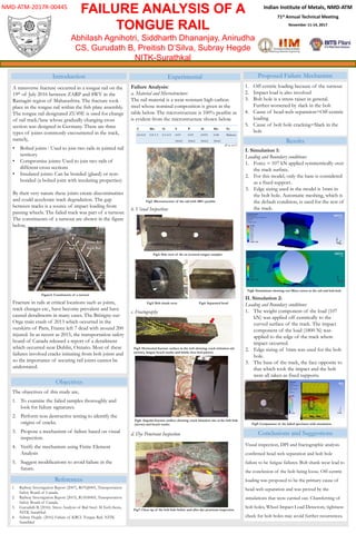
- 1. Indian Institute of Metals, NMD-ATM 71st Annual Technical Meeting November 11-14, 2017 FAILURE ANALYSIS OF A TONGUE RAIL Abhilash Agnihotri, Siddharth Dhananjay, Anirudha CS, Gurudath B, Preitish D’Silva, Subray Hegde NITK-Surathkal s NMD-ATM-2017R-00445 Point Introduction A transverse fracture occurred in a tongue rail on the 19th of July 2016 between ZARP and SWV in the Ratnagiri region of Maharashtra. The fracture took place in the tongue rail within the fish plate assembly. The tongue rail designated ZU49E is used for change of rail track/lane whose gradually changing cross section was designed in Germany. There are three types of joints commonly encountered in the track, namely, • Bolted joints : Used to join two rails in jointed rail territory • Compromise joints: Used to join two rails of different cross sections • Insulated joints: Can be bonded (glued) or non- bonded (a bolted joint with insulating properties) By their very nature these joints create discontinuities and could accelerate track degradation. The gap between tracks is a source of impact loading from passing wheels. The failed track was part of a turnout. The constituents of a turnout are shown in the figure below, Fracture in rails at critical locations such as joints, track changes etc., have become prevalent and have caused derailments in many cases. The Brétigny-sur- Orge train crash of 2013 which occurred in the outskirts of Paris, France left 7 dead with around 200 injured. In as recent as 2015, the transportation safety board of Canada released a report of a derailment which occurred near Dublin, Ontario. Most of these failures involved cracks initiating from bolt joints and so the importance of securing rail joints cannot be understated. Switch Rod Stock Rail Closure Rail Frog Guard Rail Point Figure1: Constituents of a turnout The objectives of this study are, 1. To examine the failed samples thoroughly and look for failure signatures. 2. Perform non destructive testing to identify the origins of cracks. 3. Propose a mechanism of failure based on visual inspection. 4. Verify the mechanism using Finite Element Analysis 5. Suggest modifications to avoid failure in the future. Objectives (all in wt%) Experimental Failure Analysis: a. Material and Microstructure: The rail material is a wear resistant high carbon steel whose nominal composition is given in the table below. The microstructure is 100% pearlite as is evident from the microstructure shown below. b. Visual Inspection: c. Fractography d. Dye Penetrant Inspection Fig1: Microstructure of the rail with 100% pearlite Fig2: Side view of the as received tongue samples Fig3: Bolt shank wear Fig4: Separated head Fig5: Horizontal fracture surface in the web showing crack initiation site (arrow), fatigue beach marks and brittle river bed pattern Fig6: Angular fracture surface showing crack initiation site at the bolt hole (arrow) and beach marks Fig7: Close up of the bolt hole before and after dye penetrant inspection Two other cracks Through thickness crack C Mn Si S P Al Mo Fe 0.6-0.8 0.8-1.3 0.1-0.5 0.03 (max) 0.03 (max) 0.015 (max) 0.04 (max) Balance Proposed Failure Mechanism 1. Off-centric loading because of the turnout 2. Impact load is also involved 3. Bolt hole is a stress raiser in general. Further worsened by slack in the bolt 4. Cause of head-web separation=Off-centric loading 5. Cause of bolt hole cracking=Slack in the bolt all in wt% Results I. Simulation 1: Loading and Boundary conditions: 1. Force = 107 kN applied symmetrically over the track surface. 2. For this model, only the base is considered as a fixed support. 3. Edge sizing used in the model is 1mm in the bolt hole. Automatic meshing, which is the default condition, is used for the rest of the track. II. Simulation 2: Loading and Boundary conditions: 1. The weight component of the load (107 kN) was applied off centrically to the curved surface of the track. The impact component of the load (1800 N) was applied to the edge of the track where impact occurred. 2. Edge sizing of 1mm was used for the bolt hole. 3. The base of the track, the face opposite to that which took the impact and the bolt were all taken as fixed supports. Fig8: Simulations showing von Mises stress in the rail and bolt-hole Fig9: Comparison of the failed specimen with simulation Conclusions and Suggestions Visual inspection, DPI and fractographic analysis confirmed head-web separation and bolt hole failure to be fatigue failures. Bolt shank wear lead to the conclusion of the bolt being loose. Off-centric loading was proposed to be the primary cause of head-web separation and was proved by the simulations that were carried out. Chamferring of bolt holes, Wheel Impact Load Detectors, tightness check for bolt holes may avoid further recurrences. References 1. Railway Investigation Report (2007), R07Q0001, Transportation Safety Board of Canada. 2. Railway Investigation Report (2015), R15H0005, Transportation Safety Board of Canada. 3. Gurudath B, (2016). Stress Analysis of Rail Steel. M.Tech thesis, NITK Surathkal. 4. Subray Hegde. (2016) Failure of KRCL Tongue Rail. NITK Surathkal
Editor's Notes
- AIP: - Process flow per AIP phase and Risk Management - AIP Project Selection Criteria - AIP Project Examples 2. TBIE: - TBIE Process - Past TBIE sessions - Idea Execution from TBIE