
Recommended
More Related Content
What's hot
What's hot (20)
Similar to Transportation Engineering
Similar to Transportation Engineering (20)
More from Sunil Kumar Meena
More from Sunil Kumar Meena (9)
Recently uploaded
Recently uploaded (20)
Transportation Engineering
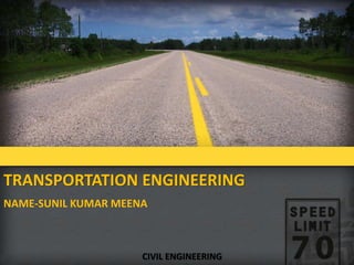
- 1. TRANSPORTATION ENGINEERING NAME-SUNIL KUMAR MEENA CIVIL ENGINEERING
- 2. WHAT IS TRANSPORTATION EGINEERING? Transportation engineering is the application of the principles of engineering, planning, analysis, and design to the disciplines comprising transportation: its vehicles, its physical infrastructure, safety in travel, environmental impacts, and energy usage. • Objective • Safe, efficient, economical transportation facilities for travel of passenger & transportation of goods.
- 3. HISTORICAL DEVELOPMENT OF ROADS EARLY DEVELOPMENT • The oldest mode of travel was on the foot-paths. • Animals were also used to transport men and materials. • Later simple animal drawn vehicles were developed and this became a common and popular mode of transportation for very along period after the invention of wheel. • This brought up the necessity of providing a hard surface for these wheeled vehicles to move on. • Such a hard surface is believed to have existed in the period of about 3500 B.C.
- 4. ROMAN ROADS(312 B.C.) FEATURES OF ROMAN ROADS • An earthed road with a graveled surface. • They were build straight without any gradient. • The soft soil from top was removed till the hard stratum was reached. • The total thickness of road section worked out as high as 750 mm to 1200 mm.
- 5. CONSTRUCTION OF ROMAN ROADS
- 6. FRENCH ROADS OR TRESAGUET ROADS (1716-1796) • The next major development in the road construction occurred during the regime of Napoleon. • The pavement used 200 mm pieces of stone of a more compact form and shaped such that they had at least one at side which was placed on a compact formation. • Smaller pieces of broken stones were then compacted into the spaces between larger stones to provide a level surface. • Finally the running layer was made with a layer of 25 mm sized broken stone.
- 7. CONSTRUCTION OF FRENCH ROADS
- 8. TELFORD CONSTRUCTION(1757-1834) • The foundation was prepared for a road with width of 9 m and it was levelled. • Large size stones of width equal to 40 mm and depth 170 to 220 mm were then laid. • After filling the spaces between foundation stones, two layers of stones having compacted thickness of 100 and 50 mm respectively laid in the center of 5.4 m. of width. • The top layer of road was made of 40 mm thick binding layer of gravel.
- 10. BRITISH OR MACADAM ROADS(1756- 1836) • The British engineer John Macadam introduced what can be considered as the first scientific road construction method. • Stone size was an important element of Macadam road. By empirical observation of many roads, he came to realize that 250 mm layers of well compacted broken angular stone would provide the same strength and stiffness and a better running surface than an expensive pavement founded on large stone blocks.Thus he introduced an economical method of road construction.
- 11. BRITISH OR MACADAM ROADS
- 12. DIFFERENCE BETWEEN TELFORD AND MACADAM CONSTRUCTION Parameter Telford Macadam Subgrade slope Horizontal 1 in 36 Foundation stone From 170 mm to 220mm. From 50 mm to 100mm. Basecourse Two layers of broken stones Onelayer of broken stone Surface course 40 mm thick with slope 1 in 45 50 mm thick with slope 1in 36 Thickness of crosssection 410 mm at center and 350 at edge Uniform 250 mm only.
- 13. FIRST 20 YEARS ROAD PLAN OR NAGPUR ROAD PLAN(1943-1963) • The target road length 16 km per 100 square km area of the country. • The conference of chief engineer held at Nagpur in 1943 finalized the first 20-years road development plan for India called Nagpur road plan. • Road network was classified into five categories. • The responsibility of construction maintenance of NH was assign to central govt. • The target road length was 5,32,700 km at the end of 1961.
- 14. SECOND 20 YEARS ROAD PLAN OR BOMBAY ROAD PLAN(1961-1981) • Target road length of 10,57,330 km or about 32 km per hundred sq km area. • Rs. 5200 crores for 1980-81 was envisaged for this plan based on 1958 price level. • 1600 km of Express ways included. • Total length of all category roads achieved by 1974 – 11.45 lakhs km, road density – 34.8 km per 100 sq.km area.
- 15. THIRD 20 YEARS ROAD PLAN OR LUCKOW ROAD PLAN(1981-2001) • Prepared by Ministry of Shipping & transport co-operation with no. of organisation. • Growth pattern envisaged in various fields. • Aim at increasing road length from 15,02,700 km in the yr 1981 to 27,02,00 km by the year 2001. • Increase in road density from 46 km per 100 sq km in 1981, to 82 km per 100 sq km in 2001.
- 16. JAYAKAR COMMITTEE(1927) • In 1927,Indian road development committee was appointed by the government with M.R. Jayakar as chairman. • Road development in the country should be made as a national interest since local govt. do not have financial and technical capacity for road development. • An extra tax should be levied on petrol from road users to create the road development fund. • To establish a semi-official ,technical institution to pool technical knowledge, sharing of ideas and to act as an advisory body. • To create a national level institution to carry research , development works and consultation.
- 17. INDIAN ROAD CONGRESS(1934) • Central semi official body known as IRC was formed in 1934. • To provide national forum for regular pooling of experience and ideas on matters related to construction and maintenance of highways. • It is a active body controlling the specification, standardization and recommendations on materials, design of roads and bridges. • It publishes journals, research publications and standard specifications guide lines. • To provide a platform for expression of professional • opinion on matters relating to roads and road transport.
- 18. MOTOR VEHICLE ACT(1939) • Road development should be made a national interest since the provincial and local govt. do not have financial and technical capacity for road development. • Levy extra tax on petrol from road users to create the road development fund. • To establish a semi-official ,technical institution to pool technical knowledge, sharing of ideas and to act as an advisory body. • To create a national level institution to carry research , development works and consultation. • Revised 1988.
- 19. GOLDEN QUADILATERAL The Golden Quadrilateral (GQ) is a national highway network connecting most of the major industrial, agricultural and cultural centres of India. It forms a quadrilateral connecting the four major metro cities of India,i.e. Delhi (north), Kolkata (east), Mumbai (west) and Chennai (south). Major highlights of the Golden Quadrilateral • It is the largest highway project completed in India. • It is the fifth longest highway project in the world. • The overall length of the Golden quadrilateral is 5,846km. • The Golden Quadrilateral passes through 13 states of India. • The project was estimated to cost INR600bn but was one such project which was completed at about half of the estimated costs at INR308.58bn.
- 20. No. Segment Total Length (km) 1. Delhi-Kolkata 1,453 km (903 mi) 2. Chennai-Mumbai 1,290 km (800 mi) 3. Kolkata-Chennai 1,684 km (1,046 mi) 4. Mumbai-Delhi 1,419 km (882 mi) Total 5,846 km (3,633 mi)
- 21. ROAD PATTERNS The various road patterns may be classified as: • Rectangular or Block pattern • Radial or star and block pattern • Radial or star and circular pattern • Radial or star and grid pattern • Hexagonal pattern
- 22. RECTANGULAR OR BLOCK PATTERN • In this pattern, the whole area is divided into rectangular blocks of plots, with streets intersecting at right angles.
- 23. RADIAL OR STAR AND BLOCK PATTERN • In this pattern, the entire area is divided into a network of roads radiating from the business outwardly. In between radiating main roads, the builtuparea may be planned with rectangular block.
- 24. RADIAL OR STAR AND CIRCULAR PATTERN
- 25. RADIAL OR STAR AND GRID PATTERN
- 27. 4 E’s OF TRANPORTATION • EDUCATION • ENGINEERING • ENCOURAGEMENT • ENFORCEMENT
- 28. CLASSIFICATION OF HIGHWAYS Depending on weather • All weather roads • Fair weather roads Depending the type of Carriage way • Paved roads(WBM) • Unpaved roads(earth road or gravel road) Depending upon the pavement surface • Surfaced roads(bituminous or cement concrete road) • Unsurfaced roads
- 29. CLASSIFICATION OF HIGHWAYS Based on the Traffic Volume • Heavy • Medium • Light Based on Load or Tonnage • Class 1 or Class 2 etc or Class A , B etc Tonnes per day Based on location and function ( Nagpur road plan ) • National highway (NH) • State highway (SH) • Major district road (MDR) • Other district road (ODR) • Village road (VR)
- 30. CLASSIFICATION OF HIGHWAYS BASED ON MODIFIED SYSTEM Primary • Expressways • National Highways Secondary • State Highways(SH) • Major District Roads(MDR) Tertiary • Other District Roads(ODR) • Village Roads(VR)
- 31. EXPRESSWAYS • Heavy traffic at high speed (120km/hr) • Land Width (90m) • Full access control • Connects major points of traffic generation • No slow moving traffic allowed • No loading, unloading, parking. MUMBAI-PUNE EXPRESSWAY
- 32. URBAN ROAD CLASSIFICATION ARTERIAL ROADS • No frontage access, no standing vehicle, very little cross traffic. • Design Speed : 80km/hr • Land width : 50 – 60m • Divided roads with full or partial parking • Pedestrian allowed to walk only at intersection.
- 33. SUB ARTERIAL ROADS • Bus stops but no standing vehicle. • Less mobility than arterial. • Spacing for CBD: 0.5km • Design speed: 60 km/hr • Land width: 30 – 40 m
- 34. COLLECTOR STREET • Collects and distributes traffic from local streets • Provides access to arterial roads • Located in residential, business and industrial areas. • Full access allowed. • Parking permitted. • Design speed : 50km/hr • Land Width : 20-30m
- 35. LOCAL STREET • Design Speed : 30km/hr. • Land Width : 10 – 20m. • Primary access to residence, business or other abutting property • Less volume of traffic at slow speed • Unrestricted parking, pedestrian movements. (with frontage access, parked vehicle, bus stops and no waiting restrictions)
- 36. CUL-DE-SAC • Dead End Street with only one entry access for entry and exit. • Recommended in Residential areas
- 37. DRIVEWAY • A driveway is a type of private road for local access to one or a small group of structures, and is owned and maintained by an individual or group. • Driveways are commonly used as paths to private garages, fuel stations, or houses.
- 39. HIGHWAY ALIGNMENT • The position or lay out of centre line of the highway on the ground is called the alignment. • It includes straight path, horizontal deviation and curves. • Due to improper alignment , the disadvantages are, Increase in construction Increase in maintenance cost Increase in vehicle operation cost Increase in accident cost • Once the road is aligned and constructed, it is not easy to change the alignment due to increase in cost of adjoining land and construction of costly structure.
- 41. REQUIREMENTS OF HIGHWAY ALIGNMENT • Short- desirable to have a short alignment between two terminal stations. • Easy- easy to construct and maintain the road with minimum problem also easy for operation of vehicle. • Safe- safe enough for construction and maintenance from the view point of stability of natural hill slope, embankment and cut slope also safe for traffic operation. • Economical- total cost including initial cost, maintenance cost and vehicle operation cost should be minimum.
- 42. HIGHWAY GEOMETRIC DESIGN • The geometric design of a highway deals with the dimensions and layout of visible features of the highway such as alignment, sight distance and intersection.
- 43. DESIGN CONTROLS AND CRITERIA • Design speed • Topography • Traffic factors • Design hourly volume and capacity • Environmental and other factors Design speed • In India different speed standards have been assigned for different class of road • Design speed may be modified depending upon the terrain conditions.
- 44. HIGHWAY CROSS SECTION ELEMENTS • Carriageway • Shoulder • Roadway width • Right of way • Building line • Control line • Median • Camber/ cross slope • Crown • Side slope • Kerb • Guard rail • Side drain • Other facilities
- 45. CARRIAGEWAY • It is the travel way which is used for movement of vehicle, it takes the vehicular loading . • It may be cement concrete road or bituminous pavement. • Width of carriageway is determined on the basis of the width of the vehicle and the minimum side clearance for safety. • As per IRC specification, the maximum width of vehicle is 2.44m,minimum clearance of 0.68m in case of single lane and 1.02m in case of double lane.
- 46. WIDTH OF CARRIAGEWAY SL. NO. Class of road Width of carriageway in ‘m’ 1 Single lane 3.75 2 Two lane without raised kerbs 7.0 3 Two lane with raised kerbs 7.5 4 Intermediate lane 5.5 5 Multilane pavement 3.5/lane
- 48. SHOULDER • It is provided along the road edge to serve as an emergency lane for vehicle. • It act as a service lane for vehicles that have broken down. • The minimum shoulder width of 4.6 m so that a truck stationed at the side of the shoulder would have a clearance of 1.85m from the pavement edge. • IRC recommended the minimum shoulder width is 2.5 m • It should have sufficient load bearing capacity even in wet weather. • The surface of the should be rougher than the traffic lanes so that vehicles are discouraged to use the shoulder as a regular traffic. • The colour should be different from that of the pavement so as to be distinct.
- 51. RIGHT OF WAY • It is the total area of land acquired for the road along its alignment. • It depends on the importance of the road and possible future development. • It is desirable to acquire more width of land as the cost of adjoining land invariably increases very much , soon after the new highway is constructed.
- 53. TRAFFIC SEPERATORS OR MEDIAN • The main function is to prevent head on collision between the vehicle moving in opposite direction. • Channelize traffic into streams at intersection. • Segregate slow traffic and to protect pedestrians. • IRC recommends a minimum desirable width of 5 m and may be reduce to 3 m where land is restricted. • The minimum width of median in urban area is 1.2m.
- 55. CROSS SLOPE OR CAMBER • It is the slope provided to the road surface in the transverse direction to drain off the rain water from the road surface. • To prevent the entry of surface water into the subgrade soil through pavement. • To prevent the entry of water into the bituminous pavement layer. • To remove the rain water from the pavement surface as quick as possible and to allow the pavement to get dry soon after the rain. • It is expressed as a percentage or 1V:Nh. • It depends on the pavement surface and amount of rainfall.
- 56. KERB • It indicates the boundary between the pavement and shoulder. • It is desirable to provide kerbs in urban areas.
- 58. GUARD RAIL • It is provided at the edge of the shoulder when the road is constructed on a fill exceeds 3 m. • It is also provided on horizontal curve so as to provide a better night visibility of the curves under the head light of the vehicle.
- 60. ROAD MARGINS Parking lane: • These are provided on urban roads to allow kerb parking. • As far as possible only parallel parking should be allowed as it is safer for moving vehicle. • It should have sufficient width say 3m . Lay bay: • These are provided near the public conveniences with guide map to enable driver to stop clear off the carriageway. • It has 3m width,30m length with 15m end tapers on both sides. Bus bays: • These may be provided by recessing the kerb to avoid conflict with moving traffic. • It is located atleast 75m away from the intersection.
- 61. Frontage road: • These are provided to give access to properties along an important highway with control access to express way or free way • It may run parallel to the highway and are isolated by separator. Driveway: • It connect the highway with commercial establishment like fuel stations, service stations etc… • It should be located away from the intersection. Cycle track: • It provided in urban areas when the volume of cycle traffic on the road • is very high. • A minimum width of 2m is provided for cycle track. Footpath: • These are provided in urban areas when the vehicular as well as pedestrian traffic are heavy. • Toprotect the pedestrian and decrease accident. • Minimum width of 1.5m is provided.
- 65. SIGHT DISTANCE • Sight distance available from a point is the actual distance along the road surface, which a driver from a specified height above the carriageway has visibility of stationary or moving objects. OR • It is the length of road visible ahead to the driver at any instance.
- 66. TYPES OF SIGHT DISTANCE • Stopping or absolute minimum sight distance(SSD) • Safe overtaking or passing sight distance (OSD) • Safe sight distance for entering into uncontrolled intersection. • Intermediate sight distance • Head light sight distance
- 67. Stopping sight distance: • The minimum sight distance available on a highway at any spot should be of sufficient length to stop a vehicle traveling at design speed, safely without collision with any other obstruction. Over taking sight distance: • The minimum distance open to the vision of the driver of a vehicle intending to overtake slow vehicle ahead with safety against the traffic of opposite direction is known as the minimum overtaking sight distance (OSD) or the safe passing sight distance. Sight distance at intersection: • Driver entering an uncontrolled intersection (particularly unsignalised Intersection) has sufficient visibility to enable him to take control of his vehicle and to avoid collision with another vehicle.
- 68. Intermediate sight distance: • This is defined as twice the stopping sight distance. When overtaking sight distance can not be provided, intermediate sight distance is provided to give limited overtaking opportunities to fast vehicles. Head light sight distance: • This is the distance visible to a driver during night driving under the illumination of the vehicle head lights. This sight distance is critical at up-gradients and at the ascending stretch of the valley curves.
- 69. STOPPING SIGHT DISTANCE • SSD is the minimum sight distance available on a highway at any spot having sufficient length to enable the driver to stop a vehicle traveling at design speed, safely without collision with any other obstruction.
- 71. FACTORS AFFECTING SSD • Total reaction time of driver • Speed of vehicle • Efficiency of brakes • Frictional resistance between road and tyre • Gradient of road
- 72. “PIEV” THEORY Total reaction time of driver is split into four parts: • P-perception • I-intellection • E-Emotion • V-Volition
- 73. Perception • It is the time required for the sensation received by the eyes or ears to be transmitted to the brain through the nervous system and spinal chord. Intellection • It is the time required for understanding the situation. Emotion • It is the time elapsed during emotional sensation and disturbance such as fear, anger or any other emotional feeling such as superstition etc, with reference to the situation. Volition • It is the time taken for the final action. Total reaction time of driver may be vary from 0.5 sec to 4 sec.
- 74. 1
- 75. OVERTAKNG SIGHT DISTANCE(OSD) • The minimum distance open to the vision of the driver of a vehicle intending to overtake slow vehicle ahead with safety against the traffic of opposite direction is known as the minimum overtaking sight distance(OSD) or the safe passing sight distance. • The overtaking sight distance or OSD is the distance measured along the centre of the road which a driver with his eye level 1.2 m above the road surface can see the top of an object 1.2 m above the road surface.
- 76. FACTORS AFFECTING OSD • speeds of overtaking vehicle overtaken vehicle the vehicle coming from opposite direction, if any. • Distance between the overtaking and overtaken vehicles. • Skill and reaction time of the driver • Rate of acceleration of overtaking vehicle • Gradient of the road
- 79. SUPERELEVATION • In order to counteract the effect of centrifugal force and to reduce the tendency of the vehicle to overturn or skid, the outer edge of the pavement is raised with respect to the inner edge, thus providing a transverse slope throughout the length of the horizontal curve, this transverse inclination to the pavement surface is known as Superelevation or cant or banking. • The Superelevation ‘e’ is expressed as the ratio of the height of outer edge with respect to the horizontal width.
- 82. • e = rate of Superelevation = tan Ө • f = design value of lateral friction coefficient = 0.15 • v = speed of the vehicle, m/sec • R = radius of the horizontal curve, mg = acceleration due to gravity = 9.8 m/sec²
- 83. MAXIMUM SUPERELEVATION • In the case of heavily loaded bullock carts and trucks carrying less dense materials like straw or cotton, the centre of gravity of the loaded vehicle will be relatively high and it will not be safe for such vehicles to move on a road with a high rate of Superelevation. Because of the slow speed, the centrifugal force will be negligibly small in the case of bullock carts. Hence to avoid the danger of toppling of such loaded slow moving vehicles, it is essential to limit the value of maximum allowable Superelevation. • Indian Roads Congress had fixed the maximum limit of Superelevation in plan and rolling terrains and is snow bound areas as 7.0 %. • On hill roads not bound by snow a maximum Superelevation upto 10%. • On urban road stretches with frequent intersections, it may be necessary to limit the maximum Superelevation to 4.0 %.
- 84. MINIMUM SUPERELEVATION • From drainage consideration it is necessary to have a minimum cross to drain off the surface water. If the calculated Superelevation is equal to or less than the camber of the road surface, then the minimum Superelevation to • be provided on horizontal curve may be limited to the camber of the surface.
- 85. GRADIENT • It is the rate of rise or fall along the length of the road with respect to the horizontal. It is expressed as a ratio of 1 in x (1 vertical unit to x horizontal unit). Some times the gradient is also expressed as a percentage i.e. n% (n in 100). TYPES OF GRADIENT(IRC) • Ruling Gradient • Limiting Gradient • Exceptional gradient • Minimum Gradient
- 86. RULING GRADIENT- • It is the maximum gradient within which the designer attempts to design the vertical profile of road, it depends on Type of terrain Length of grade Speed Pulling power of vehicles Presence of horizontal curves Mixed traffic
- 87. LIMITING GRADIENT • Steeper than ruling gradient. In hilly roads, it may be frequently necessary to exceed ruling gradient and adopt limiting gradient, it depends on Topography Cost in constructing the road
- 88. EXCEPTIONAL GRADIENT • Exceptional gradient are very steeper gradients given at unavoidable situations. They should be limited for short stretches not exceeding about 100 m at a stretch. critical length of the grade: • The maximum length of the ascending gradient which a loaded truck can operate without undue reduction in speed is called critical length of the grade. A speed of 25 kmph is a reasonable value. This value depends on the size, power, load, initial speed.
- 89. MINIMUM GRADIENT • This is important only at locations where surface drainage is important. Camber will take care of the lateral drainage. But the longitudinal drainage along the side drains require some slope for smooth flow of water. Therefore minimum gradient is provided for drainage purpose and it depends on the rain fall, type of soil and other site conditions. • A minimum of 1 in 500 may be sufficient for concrete drain and 1 in 200 for open soil drains.
- 91. WIDENING OF PAVEMENT ON HORIZONTAL CURVES • On horizontal corves, especially when they are not of very large radii, it is common to widen the pavement slightly more than the normal width, • Widening is needed for the following reasons : The driver experience difficulties in steering around the curve. The vehicle occupies a greater width as the rear wheel don’t track the front wheel. known as ‘Off tracking’. For greater visibility at curve, the driver have tendency not to follow the central path of the lane, but to use the outer side at the beginning of the curve. While two vehicle cross or overtake at horizontal curve there is psychological tendency to maintain a greater clearance between the vehicle for safety.
- 93. ANALYSIS OF EXTRA WIDENING • It is divided into two parts; Mechanical widening (Wm): the widening required to account for the off tracking due to the rigidity of wheel base is called mechanical widening Psychological widening (Wps): extra width of the pavement is also provided for psychological reasons such as , to provide for greater maneuverability of steering at high speed, to allow for the extra space for overhangs of vehicles and to provide greater clearance for crossing and overturning vehicles on curve. • Total widening W = Wps+ Wm
- 94. MECHANICAL WIDENING Wm = l2 / (2 R2 – Wm) Wm = l2 / 2 R (Approx.) or Wm=nl²/2R • Where, R = Mean radius of the curve in m, n=no. of traffic lanes • R = Mean radius of the curve, m • I= Length of Wheel base of longest vehicle , m ( l = 6.0 m or 6.1m for commercial vehicles) • V= design speed, kmph
- 96. SIGNAGES
- 97. SIGNAGES Signage is a comprehensive system of Regulatory, Informatory and Warning messages corresponding to the information for all road user groups. An effective Signage System keeps the road user informed of the following: 1.Important destinations and routes 2.Unexpected conditions 3.Traffic laws 4.Facilities like Public conveniences and Parking areas. 5.Differently-abled environments.
- 98. TYPES OF SIGNAGES • The Signage System comprises of three internationally accepted categories of signages, on the basis of the user group to be addressed and information to be delivered, represented using three basic geometric shapes. • Regulatory Signs – Circle • Regulatory Signs – Circle • Informatory Sign - Square/ Rectangular
- 99. REGULATORY SIGNS To inform road users of traffic laws. These include signs such as, STOP, YIELD, SPEED LIMIT, etc. Shape & color: The signs shall be in shape of a circle, with a red (retro-reflective) border and a white background. 1.Speed Limit Sign: For Truck and Car Users Size : 600mm Diameter Background : White Border : Red Symbol / Text : Black
- 100. 2.No Free Left: Used at signalised left turnings. Top: 600mm Diameter Bottom: 600mm x 200mm Background: White Border: Top - Red, Bottom- Black - 10mm Symbol / Text : Black NEW SIGNS 3. Prohibited Parking in Non- Motorized Lines: Used to prohibit parking on the segregated cycle lane. Size:Top - 600mm Diameter, Bottom-350mm x 250mm Background: White Border: Top - Red, Bottom - Black - 10mm Symbol / Text: Black
- 101. 4. Tow Away Zone: Use of tow away signs at strategic locations where there is ‘No Parking’. Size:Top: 600mm Diameter, Bottom: 350mm x 200mm Background Colour: White Border :Top-Red, Bottom-Black Symbol / Text: Black 5. Compulsory MV Lane: Regulatory sign for segregated MV Lane, with an arrow pointing towards the location. Size : 900mm x 900mm Background Colour:White Border :Top-Red, Bottom-Black Symbol / Text: Black
- 102. 6.Compulsory Bus Lane: Hung at the gantry right above the bus lane, at the far sight of the junction to guide bus users to their dedicated lanes. Size : 900mm x 900mm Background Colour:White Border:Top-Black (outer) and Red (inner), Bottom-Black Symbol / Text: Black An arrow could be added for assistance. 7.Left Bus Lane Size : 900mm x 900mm Background Colour:White Border :Top-Red, Bottom-Black Symbol / Text: Black
- 103. 8. Bus Lane Regulatory Size : 600mm x 900mm Background Colour:White Border:Top-Black (outer) and Red (inner), Bottom-Black Symbol / Text: Black
- 104. Stop & Give Way Signs StopSign Diameter Size :600mm Background Color: White Border: Red Symbol / Text: Black GiveWay Sign Diameter Size: 600mm Color : Background: White Border: Red Symbol / Text: Black PROHIBITORYSIGNS Straight Prohibited/ No Entry PROPOSED
- 105. Oneway Diameter Size:600mm Background Color : White Border : Red Symbol / Text: Black Vehiclesprohibited in bothdirections DiameterSize:600mm Background Color : White Border :Red Symbol / Text : Black
- 106. All motorvehicles prohibited Diameter Size: 600mm Background Color : White Border: Red Symbol / Text: Black TrucksProhibited Diameter Size: 600mm Background Color : White Border :Red Symbol / Text: Black Bullockcart & HandCarts Prohibited Diameter Size: 600mm Background Colour:White
- 107. Border : Red Symbol / Text : Black BullockCart Prohibited Diameter Size:600mm Background Colour : White Border : Red Symbol / Text: Black TongasProhibited HandCarts Prohibited Size :600mm Diameter Color : Background : White Border : Red
- 108. Symbol / Text : Black CycleProhibited Diameter Size :600mm Color : Background : White Border : Red Symbol / Text : Black Pedestrian Prohibited Diameter Size :600mm Background Color : White Border : Red Symbol / Text : Black Right/Left Turn Prohibited
- 109. U-Turn Prohibited Diameter Size :600mm Background Color : White Border : Red Symbol / Text : Black OvertakingProhibited Size :600mm Diameter Horn Prohibited Color : Background : White Border : Red Symbol / Text : Black No Parking Size :600mm Diameter
- 110. Background colour : White Border : Red Symbol / Text : Black NoStopping/ Standing Diameter Size:600mm Color : Background : White Border : Red Symbol / Text : Black SpeedLimit Diameter Size:600mm Color : Background : White Border : Red Symbol / Text : Black
- 111. Minimum SpeedLimit Diameter Size:600mm Color : Background : White Border : Red Symbol / Text : Black SpeedCameraSigns Diameter Size :600mm Color : Background : White Border : Red Symbol / Text : Black Width Limit Diameter Size :600mm
- 112. Background colour: White Border : Red Symbol / Text : Black HeightLimit Diameter Size:600mm Color : Background : White Border : Red Symbol / Text : Black LengthLimit Diameter Size:600mm Color : Background : White Border : Red Symbol / Text : Black
- 113. LoadLimit Diameter Size :600mm Color : Background : White Border : Red Symbol / Text : Black Axle LoadLimit Diameter Size :600mm Color : Background : White Border : Red Symbol / Text : Black GivePriority to Traffic Coming TrafficOpposite Direction Diameter Size :600mm Color : Background White :
- 114. Border : Red Symbol / Text : Black Stopfor PoliceCheck Size :600mm Diameter Color : Background : White Border : Red Symbol / Text : Black Restriction EndsSign Compulsory Direction Control And Other Signs CompulsoryTurn Left/Right
- 115. CompulsoryAhead & TurnLeft/ Right CompulsoryAhead Diameter Size :600mm Background Color : White Border : Red Symbol / Text : Black CompulsoryKeepLeft Size :600mm Diameter Background Color : White Border : Red Symbol / Text : Black
- 116. Compulsorycycle track/cycles only Diameter Size :600mm Color : Background : White Border : Red Symbol / Text : Black Compulsorysoundhorn Diameter Size :600mm Color : Background : White Border : Red Symbol / Text : Black Pedestriansonly Diameter Size :600mm Color : Background White :
- 117. Border : Red Symbol / Text : Black Busway/ busesonly Diameter Size :600mm Color : Background : White Border : Red Symbol / Text : Black Passeitherside Diameter Size :600mm Color : Background : White Border : Red Symbol / Text : Black
- 118. NoTractors/Construction vehicles Diameter Size :600mm Color : Background : White Border : Red Symbol / Text : Black No riding Diameter Size :600mm Color : Background : White Border : Red Symbol / Text : Black Novehiclecarrying dangerous goods
- 119. NoPowervehicles drawinga trailer Diameter Size :600mm Color : Background : White Border : Red Symbol / Text : Black CombinationRightTurn & U- Turn Prohibited Diameter Size :600mm Color : Background : White Border : Red Symbol / Text : Black HitchHikingProhibited Diameter Size :600mm Color : Background White :
- 120. Border : Red Symbol / Text : Black StopPayToll Diameter Size :600mm Color Background: White Border : Red Symbol / Text : Black Indication OfCameras UsedTraffic Lights Diameter Size :600mm Color Background: White Border : Red Symbol / Text : Black
- 121. BusesProhibited Diameter Size :600mm Color : Background : White Border : Red Symbol / Text : Black LeftTurnProhibited On RedSignal Diameter Size :600mm Color : Background : White Border : Red Symbol / Text : Black CompulsorySnowChain Diameter Size :600mm Color : Background White :
- 122. Border : Blue Symbol / Text : Black CompulsorySeat Belt Diameter Size :600mm Color Background : White Border : Red Symbol / Text : Black CompulsoryRouteFor Cyclists& Pedestrians Diameter Size :600mm Color Background: White Border :Red Symbol / Text: Black
- 123. SegregatedCycle& Pedestrian Route Diameter Size :600mm Color Background White Border : Red Symbol / Text: Black CompulsoryRoutefor Cycles& Buses Diameter Size :600mm Color Background : White Border : Red Symbol / Text : Black
- 124. WARNING SIGNAGES To alert the road users of unexpected conditions. These include pedestrian crossing, ‘T’ or ‘Y’ intersection, etc. Shape & color: The signs shall be in shape of an equilateral triangle, with apex pointing upwards. It has a red (retro reflective) border and white background. The symbol will be black. To give emphasis to pedestrians and cyclists certain symbols have yellow background. 1.T-Junctions- Used at T-Junctions, this sign can be mounted on a blinker pole. Size : 600mm x 900mm Background Colour:White Border:Red Symbol / Text: Black
- 125. 2. School-Used to warn motorised vehicle users ofschool ahead. 3.Pedestrian Crossing- To warn motorists of the Pedestrian Crossing facility ahead, these signs are put 10-15mts before the crossings.
- 126. 4.Merging Traffic-Used to warn the motorised vehicle users of the merging traffic, at locations like the foot of the flyover.
- 127. THANK YOU