ce ms.pptx
•Download as PPTX, PDF•
3 likes•416 views

capillary electrophoresis -mass spectroscopy,ce-ms hyphenation

Recommended
More Related Content
What's hot
What's hot (20)
Similar to ce ms.pptx
Similar to ce ms.pptx (20)
More from Amrita Vshwavidyapeetham , Amrita School Of Pharmacy
More from Amrita Vshwavidyapeetham , Amrita School Of Pharmacy (7)
Recently uploaded
Recently uploaded (20)
ce ms.pptx
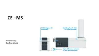
- 1. CE –MS Presented by- Sandeep bindra
- 2. INTRODUCTION: - .Capillary electrophoresis (CE) coupled to mass spectrometry (MS) was first established as an analytical tool in 1987. • CE-MS combines the high separation efficiency of CE in liquid phase and mass spectrometry in gas phase. • The orthogonal nature of these two separation techniques allows separation of unresolved analytes from CE and identification in MS. • This pairing allows for both quantitative analysis and structural elucidation.
- 3. (1)CAPILLARY ELECTROPHORESIS: - • Capillary electrophoresis is an analytical technique that separates ions based on their electrophoretic mobility with the use of an applied voltage, 1000volts/cm. • A capillary is present by connecting anode and cathode together. • The movement of components along the capillary by 2 interactions. 1. Electrophoretic mobility 2. Electroosmotic flow 1. Electrophoretic Mobility: - Electrophoresis is the process in which sample ions move under the influence of an applied voltage. The ion undergoes a force that is equal to the product of the net charge and the electric field strength. It is also affected by a drag force that is equal to the product of f, the translational friction coefficient, and the velocity. This leads to the expression for electrophoretic mobility:
- 4. • where f is force for a spherical particle is given by the Stokes’ law; η is the viscosity of the solvent, and r is the radius of the atom. The rate at which these ions migrate is dictated by the charge to mass ratio. The actual velocity of the ions is directly proportional to E, the magnitude of the electrical field and can be determined by the following equation: • This relationship shows that a greater voltage will quicken the migration of the ionic species. • 2. Electroosmotic Flow : - • The electroosmotic flow (EOF) is caused by applying high-voltage to an electrolyte-filled capillary. This flow occurs when the buffer running through the silica capillary has a pH greater than 3 and the SiOH groups lose a proton to become SiO ions. • The capillary wall then has a negative charge, which develops a double layer of cations attracted to it. The inner cation layer is stationary, while the outer layer is free to move along the capillary. • The applied electric field causes the free cations to move toward the cathode creating a powerful bulk flow. The rate of the electroosmotic flow is governed by the following equation: • where ε is the dielectric constant of the solution, η is the viscosity of the solution, E is the field strength, and ζ is the zetapotential.
- 5. (2)CAPILLARY GEL ELECTROPHORESIS- • Capillary Gel Electrophoresis (CGE) is an analytical separation method where charged molecules are separated in capillaries filled with porous gel matrix. • CGE is used to separate large biological molecules like protein, DNA, and RNA. • In free solution, these molecules have similar electrophoretic migration rates due to similar charge-to-mass ratios. However, in CGE, the non-convective medium allows them to separate based only on their size. • ADVANTAGE- Capillary Gel Electrophoresis (CGE) follows the theoretical principles of slab gel electrophoresis (SGE). In typical slab gel electrophoresis, an electric field is applied through a porous gel matrix and molecules (DNA, RNA, protein) are separated based on their size: larger molecules move slowly through the sieving matrix, while smaller molecules migrate faster.
- 7. CE-MS-
- 8. • INSTRUMENTATION: - CE-MS is the hyphenated technique where CE is connected to the MS with the help of the long capillaries which will increase the analysis time. CE: - 1. Injector 2. Capillary 3. BGE vessel (background electrolyte) 4. High voltage supply 5. Electrode 6. Detector MS: - 7. MS Interface 8. Analyzer 9. Detector
- 11. • 1.Injector: - Sample is injected into the capillary tube. The most common sample introduction is an electrokinetic and hydrostatic type of injection. • 2. Capillary: - A buffer filled fused silica capillary that is typically 10 to 100 μm in internal diameter and 40 to 100 cm long extends between two buffer reservoirs that also hold platinum electrodes. The sample is introduced at one end and detection at the other end. The detector should be placed at the right side i.e., near the cathode electrode. • 3. BGE (background electrolyte) Vessel: - Buffer plays an important role where the suitable buffer is selected for electro-osmotic and electrophoretic mobility based on analyte behavior and pH constants. Buffers chosen should be of good quality and should be prepared under optimization concentration Phosphate buffer, ethanoate buffer and borate buffers are the most commonly used buffers in CE. Buffer additives like urea, surfactants, organic & inorganic salts are also used. • 4. High Voltage Supply: - High potentials can be applied in CE; with current technology, up to 30 kV can be applied for extremely fast and efficient separations.
- 12. • 5. Electrodes: - An electrode in an electrochemical cell is referred to as either an anode or a cathode. The anode is now defined as the electrode at which electrons leave the cell and oxidation occurs and the cathode as the electrode at which electrons enter the cell and reduction occurs. Each electrode may become either the anode or the cathode depending on the direction of current through the cell. • 6.Detectors: - Separation by capillary electrophoresis can be detected by several detection devices. The most commonly used are: i) UV Absorption, ii) Fluorescence iii) Conductivity iv) Potential gradient detector v) Amperometric detector vi) Diode array detector vii) Inductive coupled plasma detector viii) Refractive index detector ix) Raman spectroscopy detector x) Chiral optical activity detector xi) Thermo optical absorbance detector xii) Atomic absorption.
- 13. 7. MS Interface: - • Electrospray ionization (ESI) • Atmospheric Pressure Photoionization (APPI) • Atmospheric Pressure Chemical ionization (APCI • Electrospray Ionization Interface (ESI): - The first CE-MS interface had cathode end of CE capillary terminated within a stainless- steel capillary. • Electrical contact was made at that point completing the circuit and initiating the electrospray. • This interface system had few drawbacks like mismatch in the flow rates of two systems. • Since then, the interface system has been improved to have a continuous flow rate and good Electrical contact. • At present, three types of interface systems exist for CE/ESI-MS which are discussed briefly.
- 14. • Sheath Less Interface: - ➢ CE capillary is coupled directly to an electrospray ionization source with a sheathless interface system. • ➢ The electric contact for ESI is realized by using capillary coated with a conductive metal. Because no sheath liquid is used, the system has high sensitivity, low flow rates and minimum background. However, these interface designs; all have challenges including low mechanical robustness, poor reproducibility. ➢ The latest sheathless interface design features porous ESI emitter through chemical etching.
- 15. • Sheath Flow Interface: - ➢ With the sheath flow interface, the electrical connection is established when the CE separation liquid is mixed with sheath liquid flowing coaxially in a metal capillary tubing. ➢ Commonly used sheath liquid is 1:1 mixture of water-methanol with 0.1% acetic acid or formic acid. ➢ The system is more reliable and has a wide selection range of separation electrolytes. ➢ There might be some decrease in sensitivity due to sheath liquid.
- 16. • Liquid Junction Interface: - ➢ In this setup, an electrode is placed at the injector extremity close to the MS inlet at the junction of two capillaries, and a voltage is applied to the system. ➢ An advantage of this setup is that the electrode's electrical contact is stable. This technique uses a stainless-steel tee to mix separation electrolytes from CE capillary with makeup liquid. The CE capillary and ESI needle are inserted through opposite sides of the tee and a narrow gap is maintained. ➢ The electrical contact is established by makeup liquid surrounding the junction between two capillaries. ➢ This system is easy to operate. However, the sensitivity is reduced and the mixing of two liquids could degrade separation.
- 17. • 8.Mass analyzer: - TOF-
- 19. • 9.Detector: - • Faraday cup detector • Electron Multiplier • Optimization Parameters for a CE/MS Analysis System- • Each CE operational mode works with a set of parameters of the CE separation that are highly specific for the particular mode. These parameters need to be chosen and optimized carefully to obtain highest resolution and sensitivity. • 1. Choosing the CE separation method and parameters: a). Mode of operation such as capillary zone electrophoresis (CZE), micellar electrokinetic capillary chromatography (MEKC), capillary gel electrophoresis (CGE), capillary isoelectric focusing (CIEF), capillary isotachophoresis (CITP), or capillary electrochromatography (CEC). b). Composition of the background electrolyte (BGE), pH, ion strength,and type of buffer, organic solvents, additives c). The separation capillary, dimensions, wall coating, temperature d). The electric field, polarity e). The injection method (in particular regarding preconcentration techniques
- 20. • 2. Choosing the CE/MS interface: a. Type of ionization; ESI, APCI, APPI b. Sheath solvent flow rate, composition and delivery c. Other operational parameters; nebulizing gas pressure, drying gas temperature, and flow rate d. Electric field and polarity for electrospray formation • Application of CE-MS- • CE-MS has been used for bioanalytical, pharmaceuticals, environmental and forensic application. • The major application of CE-MS has been for biological studies, mostly for protein and peptide analysis. • CE-MS can be used for routine clinical checkup. Body fluids like blood and urine have been analyzed with CE- MS to identify biomarkers for renal diseases and cancer • CE-MS is also possible to apply for metabolomics, particularly for single-cell metabolomics due to the minute sample volume required. Neurons, frog embryos and HeLa RBC007 cells have been already analyzed using CE-MS.
- 23. 5.1 CE‐MS for the determination of diseases of the excretory system
- 26. References- • Faserl, K., Sarg, B., & Lindner, H. H. (2020). Application of CE-MS for the analysis of histones and histone modifications. Methods (San Diego, Calif.), 184, 125–134. https://doi.org/10.1016/j.ymeth.2020.01.017 • Zhang, W., & Ramautar, R. (2021b). CE-MS for metabolomics: Developments and applications in the period 2018-2020. Electrophoresis, 42(4), 381–401. https://doi.org/10.1002/elps.202000203 • https://www.researchgate.net/publication/354143112_CE- MS_Capillary_Electrophoresis-Mass_Spectroscopy • https://en.wikipedia.org/wiki/Capillary_electrophoresis%E2%80%93mass_spectrometry
- 27. THANK YOU