
Recommended
More Related Content
What's hot
What's hot (19)
Similar to Assignment1
Similar to Assignment1 (20)
Recently uploaded
Recently uploaded (20)
Assignment1
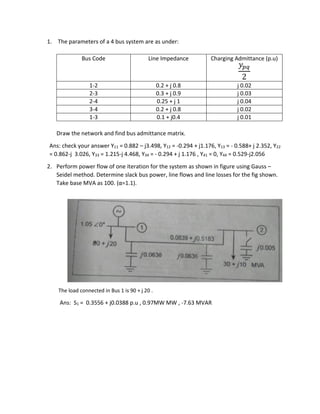
- 1. 1. The parameters of a 4 bus system are as under: Bus Code Line Impedance Charging Admittance (p.u) 𝑦𝑝𝑞 2 1-2 0.2 + j 0.8 j 0.02 2-3 0.3 + j 0.9 j 0.03 2-4 0.25 + j 1 j 0.04 3-4 0.2 + j 0.8 j 0.02 1-3 0.1 + j0.4 j 0.01 Draw the network and find bus admittance matrix. Ans: check your answer Y11 = 0.882 – j3.498, Y12 = -0.294 + j1.176, Y13 = - 0.588+ j 2.352, Y22 = 0.862-j 3.026, Y33 = 1.215-j 4.468, Y34 = - 0.294 + j 1.176 , Y41 = 0, Y44 = 0.529-j2.056 2. Perform power flow of one iteration for the system as shown in figure using Gauss – Seidel method. Determine slack bus power, line flows and line losses for the fig shown. Take base MVA as 100. (α=1.1). The load connected in Bus 1 is 90 + j 20 . Ans: S1 = 0.3556 + j0.0388 p.u , 0.97MW MW , -7.63 MVAR
- 2. 3. Using Gauss –Seidel method, determine bus voltages, slack bus power, line flows and line losses for the fig shown. Take base MVA as 100. (α=1.1) Ans: V1= 1.05∠ 0 ̊, V2= 1.02∠ 18.24 ̊, S1 = - 0.607 - j0.18 p.u , 3.3 MW , 6.33 MVAR 4. Using Gauss –Seidal method, determine bus voltages, for the figure shown in question no . 2. The reactive power limit for generator 2 in this case is 10 < Q2 < 100 MVAR. Take base MVA as 100. (α=1.1). Ans: V1= 1.05∠ 0 ̊, V2= 1.254∠ 15.26 ̊ 5. For the system shown in figure below, find the voltage at receiving bus at the end of first iteration using Gauss-Seidal method, voltage at sending end is 1.02∠ 0 ̊p.u. Line admittance is 1.0-j4 p.u. transformer reactance is j0.4 p.u and off nominal turns ratio is 1.04. Assume VR = 1 ∠ 0 ̊. Determine slack bus power. Ans: S1 = - 0.0026 + j 0.0294 p.u
- 3. 6. Use Newton Raphson Method to find the unknown quantities in the given 3 bus system. Ans: At the end of first iteration , V2= 0.91 ∠ -8.63 ̊, V3= 0.85 ∠ -12.135 ̊ 7. The load flow data for the sample power system are given below. The voltage magnitude at bus 2 is to be maintained at 1.04 p.u. The maximum and minimum reactive power limits of the generator at bus 2 are 0.35 and 0 p.u. respectively. Determine the set of load flow equations at the end of first iteration by using Newton Raphson method. In case the reactive power constraint at bus 2 in the previous problem is - 0.3 ≤ Q2 ≤ 0.3. Determine the equations at the end of first iteration.
- 4. 8. Calculate voltages and angles after one iteration by using fast decoupled load flow for the system as shown in figure . The line parameters are given in per unit on a 100 MVA base. Ans: V2= 0.951∠-10.2 ̊, V3= 0.969∠ -7.39 ̊ 9. Obtain the power flow solution (one iteration) for the system shown in figure. The line admittances are in per unit on a 100 MVA base. Use fast decoupled load flow method. Ans: V2= 1.026∠2.14 ̊, V3= 1.088∠ 10.48 ̊ 10. Write down an algorithm and draw the flowchart for Fast decoupled and Newton Rapson method of load flow studies.