SlideShare a Scribd company logo
1 of 14
Download to read offline
6.11. SYSTEMATICSHORT CIRCUIT COMPUTATION(Z BUS IN PHASE FRAME)
Fautt Analysis using Z-Bus Matrix
Algorithm: In large networks, the network reduction technique is not applicable. By
utilizing the elements ofthe bus impedance matrix, the fault current, bus voltages during the
fault can be easily calculated. To involve the digital computer in short circuit computations, it
is necessary to develop systematic, general computational procedures.
Consider a typical bus ofan n-bus system as shown in Fig.6.15. The system is assumed to
be operating under balanced condition and a per phase circuit model is used.
Step1:Draw the prefault perphase network (positive sequence network)
Each machine is represented by a constant voltage source behind proper reactance
(X, X or X) as shown in Fig.6.16.
Transmission line reactance are expressed in per unit on a common base MVA.
Eg1
Eg2
Transmission
System
Fig. 6.15. Prefuultperphase network
Let us assume 3¢ fault occurs at bus q through a fault impedance Z,.
PrefaultBus Voltages
It is obtainedfrom the powerflowsolution.
Initial bus voltages,
prefault bus voltage i.e., Z, =
Agood approximationto representthe load by a constant impedance
evaluated at the
Step2: Obtain Zematrix usingbusbuildingalgorithm.
120°
bus
the Zous
Step 3: Obtain thefault current
From Fig.6.17,
v
120°
Fig. 6.16. Equivalentcircuit
Assume one node as reference node and short circuiting all the voltage sources. Determine
usingstepbystep bus buildingalgorithm.
Let us assume the prefault currents are negligible.
Zaa
Ztn
Faultçurrent
with allother sourcs
The changes in the network voltage caused by the added voltage V'
short circuited. By representing all components and loads by their appropriate impedancs
we obtain the Thevenin's circuit as shown inFig.6.17.
..
Z-Faultimpedance
Fig. 6.17. Thevenin's circuit
(614,
where Z is the diagonal element ofthe Zhus MatriN.
Step4: Obtain the Thevenin's network by insertingthe Thevenin's voltage source V" in
series with Z,and compute change in bus voltages using network equation.
Solving for AVbus
Thecurrent entering every bus is zero except at the faulted bus.
I, = ,...........= Iy=0 except I,
Change in bus voltage
'bus(F) Ybus A V
bus
AV,
AVs ZusIbus(
AV2
AV,
LAVE
bus
=
g s: Post fault Bus Voltages
*ein the bus voltages.
Fig. 6. 18. Thevenin 's network
:
Transmission :
systerm
bus
Zi1
LZN!
Vyus U) =V+AV,bus
(F)
Z12
ZN2
o
:
[Since the fault current is leaving the bus gl
ZiN
|2
ZN
0
-I,
0
(6.20)
Post fault bus voltages are obtained by superposition of the prefault bus voltages andthe
(Zbus=YaJ
.. (6.21)
(6.22)
EIEL:
v
v
In general,
Bus voltages during thefault
v - v
v
Fault current
V
v =
= 0
N
Step 6:Post FaultLine Currents
v -Z
If theshort circuit is solid or bolted (Z=0),
Post fault line current
- ZNg
Substitute fault current from cquation (6.19) inpost faultvoltage equation (6.24), we get,
+Z,
+Zf
=
Zijs
v-v
i#4
Lij series
ZN
i#4
()
Let us consider the line connecting between busesiand jwith series impedance Lis
(6.23)
...(6.24)
..(6.25)
... (6.26)
(6.27)
(6.28)
With the knowledge of the bus impedance matrix, the fault current and bus volage
during the fault and post fault line currents are obtained for any faulted bus. This method
ery simpleand practical. Thus all fault calculations are formulated in the bus frame of
cferenceusing busimpedance matrix Z
bus
Symmetrical Fault Analysis using Zhus(Flow chart)
Read the line data, bus data, fault bus, sub-transient reactances of each machine
Assume prefault load currents, shunt elements in transformer, transformer taps,
shunt capacitance, series resistance of lines are neglected.
Draw the prefault per phase network (positive sequence network)
obtain Zbus matrix using bus building algorithm
Start
Obtain prefault bus voltages from power flow solution
Draw the Thevenin's equivalent circuit and obtain the
fault current using
|AVN
If =
Compute change in bus voltages using network equation
[AV1 |Z1 Z12 - Z1q Z4N
v
Zog t Z
ZN1 ZN2 *" ZNg
VN
Compute change in bus voltages using network equation
= Vi-Ziq
v-Zgg
... ZgN
Zii series
... ZNN
Post fault line currents
End
-If
Print I. post fault voltages, post fault line currents, etc.
Example 6.10 A symmetrical fault occurs on bus 4 of system shown in Fig.
Determine the fuult current, postfault voltages and line crrents.
Lous
Zyus
Transformer : Xteak
G, G, : 100 MVA, 20KV, X* 15%
1
Ly, L, : Xt= 10%
OSolution: Step l: Draw reactance diagram.
j0.15
= I[j0.15]
j0.09
120°
Step 2:Form Z-bus using bus building algorithm.
j0.15
2
9%
[j0.15 0.15
2Lj0.15 j0.24.
L
j0.09
Ly
j0.15
j0.1
j0.1
j0.05
3
j0.09
j0.09
-
1
j0.15
120°
4
j0.09
0000
j0.15
j0.15
Lyus
2
ifj0.15 j0.15 j0.1s1
= 2 j0.15 j0.24 j0.24
aLj0.15 j0.24 j0.29
3
j0.15 j0.15 j0.15 j0.15
2
3
2 j0.15 j0.24 j0.24 j0.24
3 j0.15 j0.24 j0.29 j0.29
aLj0.15 j0.24 j0.29 j0.38J
4
Zij
3
new
ICj0.15 j0.15 j0.15 j0.15 j0.15
4
2 j0.15 j0.24 j0.24 j0.24 j0.24
= 3 j0.15 j0.24 j0.29 j0.29 j0.29
4 j0.15 j0.24 j0.29 j0.38 j0.38
sLj0.15 j0.24 j0.29 j0.38. j0.53
Eliminate node 5using the relation,
Zij old
5
Step 3: Fault current Zog +Z
Zita +I) 2a+I)i
Zin +1)(n +1)
120°
j0.107s
j0.15
jo.15
= 9.3 Z-90° x
= 9.3L-90°x
Actual current in KA = p.U. value x Base current
j0.172 j0.13 j0.108 j0.068
j0.068 j0.108 j0. 13 j0.082
Lj0.0424 j0.13 j0.082 j1.075
100
rj0.1075 j0.172 j0.068 j0.0424}
j0.09
j0.09
MVA
V3 x KV
jo.09
V3 x20
2
2
2
= 9.3 Z-90°
j0.05
j0.05
jo.0s
p.u.
26.85 KA
(3)
j0.09
j0.09
jo.15
Step4: Postfault voltages
11 KV, 30 MVA
elements are :
j0.3 p.u.
v- Vo-Z,
V
Step 5: Post fault line currents.
Generator 1, Zp.u.
Transformer 1, Zpu.
=|/0°- j0.042 x 9.3 -90° = 0.6056 n.
= |20°- j0.082 x 9.3 Z-90° = 0.2374 nu
v = yo-Zy xl,
1Z0°-j0.068 x 9.3 Z-90°=0.3686
= |20°-j0.1075 x 9.3 Z-90° = 0 p.u.
new
new
=
= 2.634 p.u.
=
ijseries
V-v
Example 6.1|Generator G, and G, are identical and ratedas 11 KV, 30MVÀ nd
have a transient reactance of 0.3 p.u. at own MVAbase. The transformers T; and T, are
also identical and are rated 11/66 KV, 10 MVAand have a reactance of 0.075 per unit to
their own MVAbase. Then the line is 60 km long, each conductor has a reactance of
0.3686 -0.2374
j0.05
v-V
j0.075 p.u.
11/66 KV, 10 MVA
F
= j0.3
= 2.63 p.u.
0.2374-0
j0.09
j0.075 x
T2
Solution : Choose common base MVA as 30 MVA, then the reactance of various
= 2.637 p.u.
j0.075 p.u.
-(H-[0
0.6056 -0.3686
j0.09
66/11 KV, 10 MVA
11 KV, 30 MVA,
j0.3 p.u
= j0.3
= j0.225 p.u.
0.92 Okm. The 3 phasefault is assumed at point F, which is 25 km from generator G
Find the short circuit current.
Faulh
Transmissionline, Zpu.
Transforner 2, Zpu. new
Generator 2, Zpu.
Reactance diagram :
j0.3
j0.6834
Q000
XG1
120°
(0.92 x25) x
Example 6.12
=j0.3 x
F
= j0.075x
j0.225
Fault current I, =
Base current Ipase
Q000
Actual fault current in amperes is
j0.7468
120°
(
j0.1584
66)2
30 × 103
V3 x 66
66
6
XTL1
ETh 120°
XTh j0.3568
I, = 2.8023 - 90°
= |I||x Ihase
= 735.413 A
66 30
30
. Actual fault current = 2.8023 x 262.432
662
301|
j0.2218
XTL2
= 262.432 A
= j0.1584 p.u.
= j0.225 p.u.
= j0.3 p.u.
j0.225
j0.3568
= -j2.8023 p.u.
XG2 j03
)120°
If
Theone line diagram ofasimple three-bus system is as shown in Fig.
Each Benerator is represented by an emf behind the transient reactance. Allimpedances
are expressed in p.u. on acommon l00 MVA base, and
19 Determine the fault current, the bus voltages and the line currents during the fault
When a balanced three-phase fault with afault inpedance Z, =j0.19 per unit
OcCurs on bus 3.
new
new
j0.05
Z10
Zz0
(6) For bolted fault, detèrminefault current, bus voltages, lineflows.
OSolution : Case (a) : Find Thevenin equivalent impedance.
Zy0
Voltage source is Short circuited and the fault impedance open-circuited.
j0.05
j0.3
=
j0.76
j0.3
j=1
Converting A-connected network into Yconnected network using the formula,
j0.75
j0.225
jl.5
O.C
Z, xZi+1)
0.75 xj0.3
j0.75 +j0.45 +j0.3
j0.45
= j0.15
)/0.075
j0.75 xj0.45
j0.075
j0.75 +j0.45 +
10.3 *j0.225
=
j0.45 x j0.3
j0.75 +j0.45 +j0.3 j0.09
Thevenin's equivalent circuit
0 05
j0.16
j0.2
Fig. 5
Fig. i
Fig.3
1z0°
4
N
j0.12 +j0.09 =j0.21
Zoc
+
lo1()
j0.09
j0.09
ZTh
j0.05
j0225
j0.3
3
Fault current = Z tZ
Eth
j0.15
j0.075
j0.2 xj0.3
j0.2 +j03
ZTh = Za3 j0.21
=j0.12
j0.21
j0.225
j0.09
1Z0°
j0.21 +j0.19
140°
j015
Fig. 6.19.
j0 05
Fig. 4
A
Fig, 2
jo 09
j0225
j0.09
Z4-j0.19
= j2.5 p.u.
j0.075
j0075
Current contributed by generator I from Fig.6.19,
Ia
Bus voltages :
Current contributed by generator 2,
l2
Lineflows during thefautt :
V-V2
2 Li2 series
V,-V;
Z13 series
V,-V)
Bus voltage during the ault at bus I, v Vt t AV,
Z2 series
, x j0.2 +j0.3
Bus voltage during the fault at bus 2 =
= -I3
Bus voltage during the fault at bus 3 =
Erh
xj0.2 +j0.3
Fault current l ZTh
j0.3
j0.2
tbus 2 =
=
Current contributed by generator 2
Bus voltage during the fault at bus 1
Case (b) : For thebolted fault, Z,= 0
Current contributed by generator l =
=
j0.75
=
0.925 -0.925
=
=
j0.45
=
0.475 -0.925
=
V
-j2.5 xj0.3
j0.2 +j0.3
Vp.-G x
Z0
-j2.5 xj0.2
|20° (-jl.5xj0.05) = (0.925 p.u.
Vr t AV,
0.925 -0.4IS 15 p.u. = 1.5 2-90°
0.475
j0.3
j0.5
= 120°+j0.19(-j2.5) -1Z 0
= 0.475 p.u.
= -jl.0 =1.0 -90° p.u.
l20°- (-jl.0)xj0.075 = 0.925 p.u.
v = V,tAV,
120°
j0.21=-J4.76 p.u.
L, xj0.3
j0.2 +j0.3
=
= 0 p.u.
=-j1.5
L xj0.2
j0.2 +j0.3
2+j0.3
Vnr +AV,
=-jl.5 p.u.
=-jl.0 p.u.
=jl.0 p.u. = 1.0Z90° p.u.
= 0.8575 p.u.
-j2.857 p.u.
= p.u.
-jl.904
120° +
(G1Z)=1Z0°-(-j2.85) xj0.05
p.u.
V =V,t AV, = 1.0+(lGz xZzo)
Line flows during the fault 1, =
j0.05
j0.05
j0.3
j0.76
j0.425 &
j0.75
V= V, +AV, = |20°-I20° =
j0.75
j0.3 andj0.45 are in series
o045
j0.075
j0.05 and j0.375 are in series
12
120°
I20°-(-l.904) x/0.075
-0,8572 p.u.
j0.075
V,-V)
Example 6.13 For the previous Example 6.12, assume fault occurs at bus Z.
Determinefault current, bus voltages andline voltageflows during the faultforcase (4).
O
Solution: Find Thevenin's equivalent impedance,
j0.075
Z12 series
V- V,
Z13 series
Z13 series
120°
0.8575--0.8572
jo.05
j0.75
0.8575 -0
j0.3
0.8572 -0
j0.45
j0.375
j0.75 j0.75 =j0.375 p.u.
j0.06375
0
=-j2.858 p.u.
-j0.0004 p.u.
=-jl.9049 p.u.
j0.075
120
ZTh = Zz2 j0.06375
Faultcurrent I,
Current contribution by generators:
Bus voltages & Line flows :
From Fig.1,
V
Current contribution by generator 1, lG =
=
I3 =
V.
10°
j0.06375 +
j0.19
jO.05 +j0.375]
Current contributed by generator 2, IG2 = (-j3.94) x j0.05 +j0.375 +j0.075
L3=
j0 05
VË-V2
j0.375
= Vpt t AV, = 120°-lGË xZi0
Z=j1,9|I
Z12 series
= 120° -(-j0.591) xj0.05 = 0.97 p.u.
V;-V,
-j3.94 p.u.
Z3 serics
2
p.rtAV = l20°- I XZn
I,xj0.075
j0.05 +j0.375 +j0.075
-j3.94xj0.03 - -j0.591 p.u.
=
j0.5
= -j3.349 p.u.
= |20°-(-j3.349) xj0.075 = 0.7488 p.u.
0.97-0.7488
j0.75
lG-I2 = -j0.591 -(-j0.295) = -j0.296 p.u.
Vi3 = I3x Z13 series =-j0.296 xj0.3 = 0.089 p.u.
j0075
0.7488-0.881
j0.45
v{ = V-Vi3 = 0.97-0.089 = 0.881 p.u.
-j0.295 p.u.
= j0.294 p.u.

More Related Content

What's hot

The admittance model and network calculation
The admittance model and network calculationThe admittance model and network calculation
The admittance model and network calculationBalaram Das
 
Phase Lock Loop control of dc drive
Phase Lock Loop control of dc drivePhase Lock Loop control of dc drive
Phase Lock Loop control of dc driveraviarmugam
 
Power System Analysis!
Power System Analysis!Power System Analysis!
Power System Analysis!PRABHAHARAN429
 
Exp 1 (1) 1. To compute the fault level, post-fault voltages and currents for...
Exp 1 (1) 1.	To compute the fault level, post-fault voltages and currents for...Exp 1 (1) 1.	To compute the fault level, post-fault voltages and currents for...
Exp 1 (1) 1. To compute the fault level, post-fault voltages and currents for...Shweta Yadav
 
Three level inverter
Three level inverterThree level inverter
Three level inverterVinay Singh
 
Exp 3 (1)3. To Formulate YBUS Matrix By Singular Transformation.
Exp 3 (1)3.	To Formulate YBUS Matrix By Singular Transformation.Exp 3 (1)3.	To Formulate YBUS Matrix By Singular Transformation.
Exp 3 (1)3. To Formulate YBUS Matrix By Singular Transformation.Shweta Yadav
 
Transient stability analysis on a multi machine system in psat
Transient stability analysis on a multi machine system in psatTransient stability analysis on a multi machine system in psat
Transient stability analysis on a multi machine system in psateSAT Journals
 
Automatic load frequency control
Automatic load frequency controlAutomatic load frequency control
Automatic load frequency controlBalaram Das
 
Dynamic voltage restorer
Dynamic voltage restorerDynamic voltage restorer
Dynamic voltage restorerLutif Mandhro
 
Load Frequency Control of Two Area System
Load Frequency Control of Two Area SystemLoad Frequency Control of Two Area System
Load Frequency Control of Two Area SystemManash Deka
 
Auto synch considerations methods
Auto synch considerations methodsAuto synch considerations methods
Auto synch considerations methodsmichaeljmack
 
Newton Raphson method for load flow analysis
Newton Raphson method for load flow analysisNewton Raphson method for load flow analysis
Newton Raphson method for load flow analysisdivyanshuprakashrock
 
EE 6005 power quality unit I
EE 6005 power quality unit  IEE 6005 power quality unit  I
EE 6005 power quality unit IViigneshs
 
Economic load dispatch
Economic load  dispatchEconomic load  dispatch
Economic load dispatchDeepak John
 
Unit1 And 2 Sample Solutions
Unit1 And 2 Sample SolutionsUnit1 And 2 Sample Solutions
Unit1 And 2 Sample SolutionsAbha Tripathi
 

What's hot (20)

Fault analysis
Fault analysisFault analysis
Fault analysis
 
The admittance model and network calculation
The admittance model and network calculationThe admittance model and network calculation
The admittance model and network calculation
 
Phase Lock Loop control of dc drive
Phase Lock Loop control of dc drivePhase Lock Loop control of dc drive
Phase Lock Loop control of dc drive
 
Power System Analysis!
Power System Analysis!Power System Analysis!
Power System Analysis!
 
Per unit analysis
Per unit analysisPer unit analysis
Per unit analysis
 
Exp 1 (1) 1. To compute the fault level, post-fault voltages and currents for...
Exp 1 (1) 1.	To compute the fault level, post-fault voltages and currents for...Exp 1 (1) 1.	To compute the fault level, post-fault voltages and currents for...
Exp 1 (1) 1. To compute the fault level, post-fault voltages and currents for...
 
load flow 1
 load flow 1 load flow 1
load flow 1
 
Three level inverter
Three level inverterThree level inverter
Three level inverter
 
Exp 3 (1)3. To Formulate YBUS Matrix By Singular Transformation.
Exp 3 (1)3.	To Formulate YBUS Matrix By Singular Transformation.Exp 3 (1)3.	To Formulate YBUS Matrix By Singular Transformation.
Exp 3 (1)3. To Formulate YBUS Matrix By Singular Transformation.
 
Transient stability analysis on a multi machine system in psat
Transient stability analysis on a multi machine system in psatTransient stability analysis on a multi machine system in psat
Transient stability analysis on a multi machine system in psat
 
Automatic load frequency control
Automatic load frequency controlAutomatic load frequency control
Automatic load frequency control
 
Dynamic voltage restorer
Dynamic voltage restorerDynamic voltage restorer
Dynamic voltage restorer
 
Power flow analysis
Power flow analysisPower flow analysis
Power flow analysis
 
Load Frequency Control of Two Area System
Load Frequency Control of Two Area SystemLoad Frequency Control of Two Area System
Load Frequency Control of Two Area System
 
Auto synch considerations methods
Auto synch considerations methodsAuto synch considerations methods
Auto synch considerations methods
 
Newton Raphson method for load flow analysis
Newton Raphson method for load flow analysisNewton Raphson method for load flow analysis
Newton Raphson method for load flow analysis
 
EE 6005 power quality unit I
EE 6005 power quality unit  IEE 6005 power quality unit  I
EE 6005 power quality unit I
 
Economic load dispatch
Economic load  dispatchEconomic load  dispatch
Economic load dispatch
 
Unit1 And 2 Sample Solutions
Unit1 And 2 Sample SolutionsUnit1 And 2 Sample Solutions
Unit1 And 2 Sample Solutions
 
Single line diagram
Single line diagramSingle line diagram
Single line diagram
 

Similar to SYSTEMATIC SHORT CIRCUIT COMPUTATION USING Z BUS

Electronics and communication engineering_Lect14.ppt
Electronics and communication engineering_Lect14.pptElectronics and communication engineering_Lect14.ppt
Electronics and communication engineering_Lect14.pptmuhammadzaid733820
 
Newton raphson method
Newton raphson methodNewton raphson method
Newton raphson methodNazrul Kabir
 
Stability with analysis and psa and load flow.ppt
Stability with analysis and psa and load flow.pptStability with analysis and psa and load flow.ppt
Stability with analysis and psa and load flow.pptZahid Yousaf
 
Load flow study Part-II
Load flow study Part-IILoad flow study Part-II
Load flow study Part-IIAsif Jamadar
 
NR-Power Flow.pdf
NR-Power Flow.pdfNR-Power Flow.pdf
NR-Power Flow.pdfLucasMogaka
 
Load flow study Part-I
Load flow study Part-ILoad flow study Part-I
Load flow study Part-IAsif Jamadar
 
Unit1 and 2 sample solutions
Unit1 and 2 sample solutionsUnit1 and 2 sample solutions
Unit1 and 2 sample solutionsAbha Tripathi
 
EE6501 Power System Analysis Rejinpaul_Important_Questions
EE6501 Power System Analysis Rejinpaul_Important_QuestionsEE6501 Power System Analysis Rejinpaul_Important_Questions
EE6501 Power System Analysis Rejinpaul_Important_QuestionsSanthosh Kumar
 
UNIT-III complex reactive three phase.ppt
UNIT-III complex reactive three phase.pptUNIT-III complex reactive three phase.ppt
UNIT-III complex reactive three phase.pptAbinaya Saraswathy T
 
Unit 1, Power system Analysis
Unit 1, Power system AnalysisUnit 1, Power system Analysis
Unit 1, Power system AnalysisAbha Tripathi
 

Similar to SYSTEMATIC SHORT CIRCUIT COMPUTATION USING Z BUS (20)

ECE4762011_Lect14.ppt
ECE4762011_Lect14.pptECE4762011_Lect14.ppt
ECE4762011_Lect14.ppt
 
powerflowproblem.ppt
powerflowproblem.pptpowerflowproblem.ppt
powerflowproblem.ppt
 
Electronics and communication engineering_Lect14.ppt
Electronics and communication engineering_Lect14.pptElectronics and communication engineering_Lect14.ppt
Electronics and communication engineering_Lect14.ppt
 
ECE4762011_Lect14.ppt
ECE4762011_Lect14.pptECE4762011_Lect14.ppt
ECE4762011_Lect14.ppt
 
Solutions -unit4
Solutions  -unit4Solutions  -unit4
Solutions -unit4
 
Report_AKbar_PDF
Report_AKbar_PDFReport_AKbar_PDF
Report_AKbar_PDF
 
Lecture 10
Lecture 10Lecture 10
Lecture 10
 
Lecture 13
Lecture 13Lecture 13
Lecture 13
 
POWER SYSTEM 2
POWER SYSTEM 2POWER SYSTEM 2
POWER SYSTEM 2
 
Lecture 12
Lecture 12Lecture 12
Lecture 12
 
Newton raphson method
Newton raphson methodNewton raphson method
Newton raphson method
 
Stability with analysis and psa and load flow.ppt
Stability with analysis and psa and load flow.pptStability with analysis and psa and load flow.ppt
Stability with analysis and psa and load flow.ppt
 
Load flow study Part-II
Load flow study Part-IILoad flow study Part-II
Load flow study Part-II
 
NR-Power Flow.pdf
NR-Power Flow.pdfNR-Power Flow.pdf
NR-Power Flow.pdf
 
Load flow study Part-I
Load flow study Part-ILoad flow study Part-I
Load flow study Part-I
 
Unit1 and 2 sample solutions
Unit1 and 2 sample solutionsUnit1 and 2 sample solutions
Unit1 and 2 sample solutions
 
Questions unit4
Questions unit4Questions unit4
Questions unit4
 
EE6501 Power System Analysis Rejinpaul_Important_Questions
EE6501 Power System Analysis Rejinpaul_Important_QuestionsEE6501 Power System Analysis Rejinpaul_Important_Questions
EE6501 Power System Analysis Rejinpaul_Important_Questions
 
UNIT-III complex reactive three phase.ppt
UNIT-III complex reactive three phase.pptUNIT-III complex reactive three phase.ppt
UNIT-III complex reactive three phase.ppt
 
Unit 1, Power system Analysis
Unit 1, Power system AnalysisUnit 1, Power system Analysis
Unit 1, Power system Analysis
 

More from Saravanan A

Mod_1_Transformers1.ppt
Mod_1_Transformers1.pptMod_1_Transformers1.ppt
Mod_1_Transformers1.pptSaravanan A
 
Basic Introduction Biomedical.pptx
Basic Introduction Biomedical.pptxBasic Introduction Biomedical.pptx
Basic Introduction Biomedical.pptxSaravanan A
 
Distribution System
Distribution System Distribution System
Distribution System Saravanan A
 
Special Electrical Machine
Special Electrical Machine Special Electrical Machine
Special Electrical Machine Saravanan A
 
special-electrical-machines-ppt
special-electrical-machines-pptspecial-electrical-machines-ppt
special-electrical-machines-pptSaravanan A
 
ELECTROMAGNETIC FIELDS.pdf
ELECTROMAGNETIC FIELDS.pdfELECTROMAGNETIC FIELDS.pdf
ELECTROMAGNETIC FIELDS.pdfSaravanan A
 

More from Saravanan A (7)

Mod_1_Transformers1.ppt
Mod_1_Transformers1.pptMod_1_Transformers1.ppt
Mod_1_Transformers1.ppt
 
Basic Introduction Biomedical.pptx
Basic Introduction Biomedical.pptxBasic Introduction Biomedical.pptx
Basic Introduction Biomedical.pptx
 
Distribution System
Distribution System Distribution System
Distribution System
 
powerfactor.pdf
powerfactor.pdfpowerfactor.pdf
powerfactor.pdf
 
Special Electrical Machine
Special Electrical Machine Special Electrical Machine
Special Electrical Machine
 
special-electrical-machines-ppt
special-electrical-machines-pptspecial-electrical-machines-ppt
special-electrical-machines-ppt
 
ELECTROMAGNETIC FIELDS.pdf
ELECTROMAGNETIC FIELDS.pdfELECTROMAGNETIC FIELDS.pdf
ELECTROMAGNETIC FIELDS.pdf
 

Recently uploaded

Internship report on mechanical engineering
Internship report on mechanical engineeringInternship report on mechanical engineering
Internship report on mechanical engineeringmalavadedarshan25
 
microprocessor 8085 and its interfacing
microprocessor 8085  and its interfacingmicroprocessor 8085  and its interfacing
microprocessor 8085 and its interfacingjaychoudhary37
 
GDSC ASEB Gen AI study jams presentation
GDSC ASEB Gen AI study jams presentationGDSC ASEB Gen AI study jams presentation
GDSC ASEB Gen AI study jams presentationGDSCAESB
 
Application of Residue Theorem to evaluate real integrations.pptx
Application of Residue Theorem to evaluate real integrations.pptxApplication of Residue Theorem to evaluate real integrations.pptx
Application of Residue Theorem to evaluate real integrations.pptx959SahilShah
 
(ANVI) Koregaon Park Call Girls Just Call 7001035870 [ Cash on Delivery ] Pun...
(ANVI) Koregaon Park Call Girls Just Call 7001035870 [ Cash on Delivery ] Pun...(ANVI) Koregaon Park Call Girls Just Call 7001035870 [ Cash on Delivery ] Pun...
(ANVI) Koregaon Park Call Girls Just Call 7001035870 [ Cash on Delivery ] Pun...ranjana rawat
 
Oxy acetylene welding presentation note.
Oxy acetylene welding presentation note.Oxy acetylene welding presentation note.
Oxy acetylene welding presentation note.eptoze12
 
High Profile Call Girls Nagpur Meera Call 7001035870 Meet With Nagpur Escorts
High Profile Call Girls Nagpur Meera Call 7001035870 Meet With Nagpur EscortsHigh Profile Call Girls Nagpur Meera Call 7001035870 Meet With Nagpur Escorts
High Profile Call Girls Nagpur Meera Call 7001035870 Meet With Nagpur EscortsCall Girls in Nagpur High Profile
 
Study on Air-Water & Water-Water Heat Exchange in a Finned Tube Exchanger
Study on Air-Water & Water-Water Heat Exchange in a Finned Tube ExchangerStudy on Air-Water & Water-Water Heat Exchange in a Finned Tube Exchanger
Study on Air-Water & Water-Water Heat Exchange in a Finned Tube ExchangerAnamika Sarkar
 
Artificial-Intelligence-in-Electronics (K).pptx
Artificial-Intelligence-in-Electronics (K).pptxArtificial-Intelligence-in-Electronics (K).pptx
Artificial-Intelligence-in-Electronics (K).pptxbritheesh05
 
IVE Industry Focused Event - Defence Sector 2024
IVE Industry Focused Event - Defence Sector 2024IVE Industry Focused Event - Defence Sector 2024
IVE Industry Focused Event - Defence Sector 2024Mark Billinghurst
 
Biology for Computer Engineers Course Handout.pptx
Biology for Computer Engineers Course Handout.pptxBiology for Computer Engineers Course Handout.pptx
Biology for Computer Engineers Course Handout.pptxDeepakSakkari2
 
Gfe Mayur Vihar Call Girls Service WhatsApp -> 9999965857 Available 24x7 ^ De...
Gfe Mayur Vihar Call Girls Service WhatsApp -> 9999965857 Available 24x7 ^ De...Gfe Mayur Vihar Call Girls Service WhatsApp -> 9999965857 Available 24x7 ^ De...
Gfe Mayur Vihar Call Girls Service WhatsApp -> 9999965857 Available 24x7 ^ De...srsj9000
 
College Call Girls Nashik Nehal 7001305949 Independent Escort Service Nashik
College Call Girls Nashik Nehal 7001305949 Independent Escort Service NashikCollege Call Girls Nashik Nehal 7001305949 Independent Escort Service Nashik
College Call Girls Nashik Nehal 7001305949 Independent Escort Service NashikCall Girls in Nagpur High Profile
 
Architect Hassan Khalil Portfolio for 2024
Architect Hassan Khalil Portfolio for 2024Architect Hassan Khalil Portfolio for 2024
Architect Hassan Khalil Portfolio for 2024hassan khalil
 
CCS355 Neural Network & Deep Learning UNIT III notes and Question bank .pdf
CCS355 Neural Network & Deep Learning UNIT III notes and Question bank .pdfCCS355 Neural Network & Deep Learning UNIT III notes and Question bank .pdf
CCS355 Neural Network & Deep Learning UNIT III notes and Question bank .pdfAsst.prof M.Gokilavani
 
Current Transformer Drawing and GTP for MSETCL
Current Transformer Drawing and GTP for MSETCLCurrent Transformer Drawing and GTP for MSETCL
Current Transformer Drawing and GTP for MSETCLDeelipZope
 
VIP Call Girls Service Hitech City Hyderabad Call +91-8250192130
VIP Call Girls Service Hitech City Hyderabad Call +91-8250192130VIP Call Girls Service Hitech City Hyderabad Call +91-8250192130
VIP Call Girls Service Hitech City Hyderabad Call +91-8250192130Suhani Kapoor
 
VICTOR MAESTRE RAMIREZ - Planetary Defender on NASA's Double Asteroid Redirec...
VICTOR MAESTRE RAMIREZ - Planetary Defender on NASA's Double Asteroid Redirec...VICTOR MAESTRE RAMIREZ - Planetary Defender on NASA's Double Asteroid Redirec...
VICTOR MAESTRE RAMIREZ - Planetary Defender on NASA's Double Asteroid Redirec...VICTOR MAESTRE RAMIREZ
 
Software and Systems Engineering Standards: Verification and Validation of Sy...
Software and Systems Engineering Standards: Verification and Validation of Sy...Software and Systems Engineering Standards: Verification and Validation of Sy...
Software and Systems Engineering Standards: Verification and Validation of Sy...VICTOR MAESTRE RAMIREZ
 

Recently uploaded (20)

Internship report on mechanical engineering
Internship report on mechanical engineeringInternship report on mechanical engineering
Internship report on mechanical engineering
 
microprocessor 8085 and its interfacing
microprocessor 8085  and its interfacingmicroprocessor 8085  and its interfacing
microprocessor 8085 and its interfacing
 
GDSC ASEB Gen AI study jams presentation
GDSC ASEB Gen AI study jams presentationGDSC ASEB Gen AI study jams presentation
GDSC ASEB Gen AI study jams presentation
 
Application of Residue Theorem to evaluate real integrations.pptx
Application of Residue Theorem to evaluate real integrations.pptxApplication of Residue Theorem to evaluate real integrations.pptx
Application of Residue Theorem to evaluate real integrations.pptx
 
(ANVI) Koregaon Park Call Girls Just Call 7001035870 [ Cash on Delivery ] Pun...
(ANVI) Koregaon Park Call Girls Just Call 7001035870 [ Cash on Delivery ] Pun...(ANVI) Koregaon Park Call Girls Just Call 7001035870 [ Cash on Delivery ] Pun...
(ANVI) Koregaon Park Call Girls Just Call 7001035870 [ Cash on Delivery ] Pun...
 
Oxy acetylene welding presentation note.
Oxy acetylene welding presentation note.Oxy acetylene welding presentation note.
Oxy acetylene welding presentation note.
 
High Profile Call Girls Nagpur Meera Call 7001035870 Meet With Nagpur Escorts
High Profile Call Girls Nagpur Meera Call 7001035870 Meet With Nagpur EscortsHigh Profile Call Girls Nagpur Meera Call 7001035870 Meet With Nagpur Escorts
High Profile Call Girls Nagpur Meera Call 7001035870 Meet With Nagpur Escorts
 
Study on Air-Water & Water-Water Heat Exchange in a Finned Tube Exchanger
Study on Air-Water & Water-Water Heat Exchange in a Finned Tube ExchangerStudy on Air-Water & Water-Water Heat Exchange in a Finned Tube Exchanger
Study on Air-Water & Water-Water Heat Exchange in a Finned Tube Exchanger
 
Artificial-Intelligence-in-Electronics (K).pptx
Artificial-Intelligence-in-Electronics (K).pptxArtificial-Intelligence-in-Electronics (K).pptx
Artificial-Intelligence-in-Electronics (K).pptx
 
IVE Industry Focused Event - Defence Sector 2024
IVE Industry Focused Event - Defence Sector 2024IVE Industry Focused Event - Defence Sector 2024
IVE Industry Focused Event - Defence Sector 2024
 
Biology for Computer Engineers Course Handout.pptx
Biology for Computer Engineers Course Handout.pptxBiology for Computer Engineers Course Handout.pptx
Biology for Computer Engineers Course Handout.pptx
 
Gfe Mayur Vihar Call Girls Service WhatsApp -> 9999965857 Available 24x7 ^ De...
Gfe Mayur Vihar Call Girls Service WhatsApp -> 9999965857 Available 24x7 ^ De...Gfe Mayur Vihar Call Girls Service WhatsApp -> 9999965857 Available 24x7 ^ De...
Gfe Mayur Vihar Call Girls Service WhatsApp -> 9999965857 Available 24x7 ^ De...
 
College Call Girls Nashik Nehal 7001305949 Independent Escort Service Nashik
College Call Girls Nashik Nehal 7001305949 Independent Escort Service NashikCollege Call Girls Nashik Nehal 7001305949 Independent Escort Service Nashik
College Call Girls Nashik Nehal 7001305949 Independent Escort Service Nashik
 
Architect Hassan Khalil Portfolio for 2024
Architect Hassan Khalil Portfolio for 2024Architect Hassan Khalil Portfolio for 2024
Architect Hassan Khalil Portfolio for 2024
 
CCS355 Neural Network & Deep Learning UNIT III notes and Question bank .pdf
CCS355 Neural Network & Deep Learning UNIT III notes and Question bank .pdfCCS355 Neural Network & Deep Learning UNIT III notes and Question bank .pdf
CCS355 Neural Network & Deep Learning UNIT III notes and Question bank .pdf
 
Current Transformer Drawing and GTP for MSETCL
Current Transformer Drawing and GTP for MSETCLCurrent Transformer Drawing and GTP for MSETCL
Current Transformer Drawing and GTP for MSETCL
 
VIP Call Girls Service Hitech City Hyderabad Call +91-8250192130
VIP Call Girls Service Hitech City Hyderabad Call +91-8250192130VIP Call Girls Service Hitech City Hyderabad Call +91-8250192130
VIP Call Girls Service Hitech City Hyderabad Call +91-8250192130
 
VICTOR MAESTRE RAMIREZ - Planetary Defender on NASA's Double Asteroid Redirec...
VICTOR MAESTRE RAMIREZ - Planetary Defender on NASA's Double Asteroid Redirec...VICTOR MAESTRE RAMIREZ - Planetary Defender on NASA's Double Asteroid Redirec...
VICTOR MAESTRE RAMIREZ - Planetary Defender on NASA's Double Asteroid Redirec...
 
Software and Systems Engineering Standards: Verification and Validation of Sy...
Software and Systems Engineering Standards: Verification and Validation of Sy...Software and Systems Engineering Standards: Verification and Validation of Sy...
Software and Systems Engineering Standards: Verification and Validation of Sy...
 
Call Us -/9953056974- Call Girls In Vikaspuri-/- Delhi NCR
Call Us -/9953056974- Call Girls In Vikaspuri-/- Delhi NCRCall Us -/9953056974- Call Girls In Vikaspuri-/- Delhi NCR
Call Us -/9953056974- Call Girls In Vikaspuri-/- Delhi NCR
 

SYSTEMATIC SHORT CIRCUIT COMPUTATION USING Z BUS

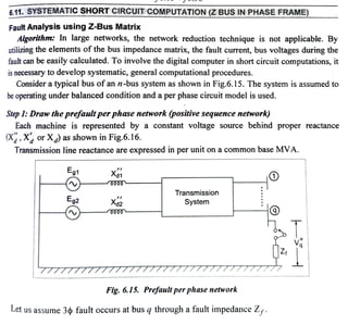
  • 1. 6.11. SYSTEMATICSHORT CIRCUIT COMPUTATION(Z BUS IN PHASE FRAME) Fautt Analysis using Z-Bus Matrix Algorithm: In large networks, the network reduction technique is not applicable. By utilizing the elements ofthe bus impedance matrix, the fault current, bus voltages during the fault can be easily calculated. To involve the digital computer in short circuit computations, it is necessary to develop systematic, general computational procedures. Consider a typical bus ofan n-bus system as shown in Fig.6.15. The system is assumed to be operating under balanced condition and a per phase circuit model is used. Step1:Draw the prefault perphase network (positive sequence network) Each machine is represented by a constant voltage source behind proper reactance (X, X or X) as shown in Fig.6.16. Transmission line reactance are expressed in per unit on a common base MVA. Eg1 Eg2 Transmission System Fig. 6.15. Prefuultperphase network Let us assume 3¢ fault occurs at bus q through a fault impedance Z,.
  • 2. PrefaultBus Voltages It is obtainedfrom the powerflowsolution. Initial bus voltages, prefault bus voltage i.e., Z, = Agood approximationto representthe load by a constant impedance evaluated at the Step2: Obtain Zematrix usingbusbuildingalgorithm. 120° bus the Zous Step 3: Obtain thefault current From Fig.6.17, v 120° Fig. 6.16. Equivalentcircuit Assume one node as reference node and short circuiting all the voltage sources. Determine usingstepbystep bus buildingalgorithm. Let us assume the prefault currents are negligible. Zaa Ztn Faultçurrent with allother sourcs The changes in the network voltage caused by the added voltage V' short circuited. By representing all components and loads by their appropriate impedancs we obtain the Thevenin's circuit as shown inFig.6.17. .. Z-Faultimpedance Fig. 6.17. Thevenin's circuit (614, where Z is the diagonal element ofthe Zhus MatriN.
  • 3. Step4: Obtain the Thevenin's network by insertingthe Thevenin's voltage source V" in series with Z,and compute change in bus voltages using network equation. Solving for AVbus Thecurrent entering every bus is zero except at the faulted bus. I, = ,...........= Iy=0 except I, Change in bus voltage 'bus(F) Ybus A V bus AV, AVs ZusIbus( AV2 AV, LAVE bus = g s: Post fault Bus Voltages *ein the bus voltages. Fig. 6. 18. Thevenin 's network : Transmission : systerm bus Zi1 LZN! Vyus U) =V+AV,bus (F) Z12 ZN2 o : [Since the fault current is leaving the bus gl ZiN |2 ZN 0 -I, 0 (6.20) Post fault bus voltages are obtained by superposition of the prefault bus voltages andthe (Zbus=YaJ .. (6.21) (6.22)
  • 4. EIEL: v v In general, Bus voltages during thefault v - v v Fault current V v = = 0 N Step 6:Post FaultLine Currents v -Z If theshort circuit is solid or bolted (Z=0), Post fault line current - ZNg Substitute fault current from cquation (6.19) inpost faultvoltage equation (6.24), we get, +Z, +Zf = Zijs v-v i#4 Lij series ZN i#4 () Let us consider the line connecting between busesiand jwith series impedance Lis (6.23) ...(6.24) ..(6.25) ... (6.26) (6.27) (6.28) With the knowledge of the bus impedance matrix, the fault current and bus volage during the fault and post fault line currents are obtained for any faulted bus. This method
  • 5. ery simpleand practical. Thus all fault calculations are formulated in the bus frame of cferenceusing busimpedance matrix Z bus Symmetrical Fault Analysis using Zhus(Flow chart) Read the line data, bus data, fault bus, sub-transient reactances of each machine Assume prefault load currents, shunt elements in transformer, transformer taps, shunt capacitance, series resistance of lines are neglected. Draw the prefault per phase network (positive sequence network) obtain Zbus matrix using bus building algorithm Start Obtain prefault bus voltages from power flow solution Draw the Thevenin's equivalent circuit and obtain the fault current using |AVN If = Compute change in bus voltages using network equation [AV1 |Z1 Z12 - Z1q Z4N v Zog t Z ZN1 ZN2 *" ZNg VN Compute change in bus voltages using network equation = Vi-Ziq v-Zgg ... ZgN Zii series ... ZNN Post fault line currents End -If Print I. post fault voltages, post fault line currents, etc.
  • 6. Example 6.10 A symmetrical fault occurs on bus 4 of system shown in Fig. Determine the fuult current, postfault voltages and line crrents. Lous Zyus Transformer : Xteak G, G, : 100 MVA, 20KV, X* 15% 1 Ly, L, : Xt= 10% OSolution: Step l: Draw reactance diagram. j0.15 = I[j0.15] j0.09 120° Step 2:Form Z-bus using bus building algorithm. j0.15 2 9% [j0.15 0.15 2Lj0.15 j0.24. L j0.09 Ly j0.15 j0.1 j0.1 j0.05 3 j0.09 j0.09 - 1 j0.15 120° 4 j0.09 0000 j0.15 j0.15
  • 7. Lyus 2 ifj0.15 j0.15 j0.1s1 = 2 j0.15 j0.24 j0.24 aLj0.15 j0.24 j0.29 3 j0.15 j0.15 j0.15 j0.15 2 3 2 j0.15 j0.24 j0.24 j0.24 3 j0.15 j0.24 j0.29 j0.29 aLj0.15 j0.24 j0.29 j0.38J 4 Zij 3 new ICj0.15 j0.15 j0.15 j0.15 j0.15 4 2 j0.15 j0.24 j0.24 j0.24 j0.24 = 3 j0.15 j0.24 j0.29 j0.29 j0.29 4 j0.15 j0.24 j0.29 j0.38 j0.38 sLj0.15 j0.24 j0.29 j0.38. j0.53 Eliminate node 5using the relation, Zij old 5 Step 3: Fault current Zog +Z Zita +I) 2a+I)i Zin +1)(n +1) 120° j0.107s j0.15 jo.15 = 9.3 Z-90° x = 9.3L-90°x Actual current in KA = p.U. value x Base current j0.172 j0.13 j0.108 j0.068 j0.068 j0.108 j0. 13 j0.082 Lj0.0424 j0.13 j0.082 j1.075 100 rj0.1075 j0.172 j0.068 j0.0424} j0.09 j0.09 MVA V3 x KV jo.09 V3 x20 2 2 2 = 9.3 Z-90° j0.05 j0.05 jo.0s p.u. 26.85 KA (3) j0.09 j0.09 jo.15
  • 8. Step4: Postfault voltages 11 KV, 30 MVA elements are : j0.3 p.u. v- Vo-Z, V Step 5: Post fault line currents. Generator 1, Zp.u. Transformer 1, Zpu. =|/0°- j0.042 x 9.3 -90° = 0.6056 n. = |20°- j0.082 x 9.3 Z-90° = 0.2374 nu v = yo-Zy xl, 1Z0°-j0.068 x 9.3 Z-90°=0.3686 = |20°-j0.1075 x 9.3 Z-90° = 0 p.u. new new = = 2.634 p.u. = ijseries V-v Example 6.1|Generator G, and G, are identical and ratedas 11 KV, 30MVÀ nd have a transient reactance of 0.3 p.u. at own MVAbase. The transformers T; and T, are also identical and are rated 11/66 KV, 10 MVAand have a reactance of 0.075 per unit to their own MVAbase. Then the line is 60 km long, each conductor has a reactance of 0.3686 -0.2374 j0.05 v-V j0.075 p.u. 11/66 KV, 10 MVA F = j0.3 = 2.63 p.u. 0.2374-0 j0.09 j0.075 x T2 Solution : Choose common base MVA as 30 MVA, then the reactance of various = 2.637 p.u. j0.075 p.u. -(H-[0 0.6056 -0.3686 j0.09 66/11 KV, 10 MVA 11 KV, 30 MVA, j0.3 p.u = j0.3 = j0.225 p.u. 0.92 Okm. The 3 phasefault is assumed at point F, which is 25 km from generator G Find the short circuit current.
  • 9. Faulh Transmissionline, Zpu. Transforner 2, Zpu. new Generator 2, Zpu. Reactance diagram : j0.3 j0.6834 Q000 XG1 120° (0.92 x25) x Example 6.12 =j0.3 x F = j0.075x j0.225 Fault current I, = Base current Ipase Q000 Actual fault current in amperes is j0.7468 120° ( j0.1584 66)2 30 × 103 V3 x 66 66 6 XTL1 ETh 120° XTh j0.3568 I, = 2.8023 - 90° = |I||x Ihase = 735.413 A 66 30 30 . Actual fault current = 2.8023 x 262.432 662 301| j0.2218 XTL2 = 262.432 A = j0.1584 p.u. = j0.225 p.u. = j0.3 p.u. j0.225 j0.3568 = -j2.8023 p.u. XG2 j03 )120° If Theone line diagram ofasimple three-bus system is as shown in Fig. Each Benerator is represented by an emf behind the transient reactance. Allimpedances are expressed in p.u. on acommon l00 MVA base, and 19 Determine the fault current, the bus voltages and the line currents during the fault When a balanced three-phase fault with afault inpedance Z, =j0.19 per unit OcCurs on bus 3. new new
  • 10. j0.05 Z10 Zz0 (6) For bolted fault, detèrminefault current, bus voltages, lineflows. OSolution : Case (a) : Find Thevenin equivalent impedance. Zy0 Voltage source is Short circuited and the fault impedance open-circuited. j0.05 j0.3 = j0.76 j0.3 j=1 Converting A-connected network into Yconnected network using the formula, j0.75 j0.225 jl.5 O.C Z, xZi+1) 0.75 xj0.3 j0.75 +j0.45 +j0.3 j0.45 = j0.15 )/0.075 j0.75 xj0.45 j0.075 j0.75 +j0.45 + 10.3 *j0.225 = j0.45 x j0.3 j0.75 +j0.45 +j0.3 j0.09
  • 11. Thevenin's equivalent circuit 0 05 j0.16 j0.2 Fig. 5 Fig. i Fig.3 1z0° 4 N j0.12 +j0.09 =j0.21 Zoc + lo1() j0.09 j0.09 ZTh j0.05 j0225 j0.3 3 Fault current = Z tZ Eth j0.15 j0.075 j0.2 xj0.3 j0.2 +j03 ZTh = Za3 j0.21 =j0.12 j0.21 j0.225 j0.09 1Z0° j0.21 +j0.19 140° j015 Fig. 6.19. j0 05 Fig. 4 A Fig, 2 jo 09 j0225 j0.09 Z4-j0.19 = j2.5 p.u. j0.075 j0075
  • 12. Current contributed by generator I from Fig.6.19, Ia Bus voltages : Current contributed by generator 2, l2 Lineflows during thefautt : V-V2 2 Li2 series V,-V; Z13 series V,-V) Bus voltage during the ault at bus I, v Vt t AV, Z2 series , x j0.2 +j0.3 Bus voltage during the fault at bus 2 = = -I3 Bus voltage during the fault at bus 3 = Erh xj0.2 +j0.3 Fault current l ZTh j0.3 j0.2 tbus 2 = = Current contributed by generator 2 Bus voltage during the fault at bus 1 Case (b) : For thebolted fault, Z,= 0 Current contributed by generator l = = j0.75 = 0.925 -0.925 = = j0.45 = 0.475 -0.925 = V -j2.5 xj0.3 j0.2 +j0.3 Vp.-G x Z0 -j2.5 xj0.2 |20° (-jl.5xj0.05) = (0.925 p.u. Vr t AV, 0.925 -0.4IS 15 p.u. = 1.5 2-90° 0.475 j0.3 j0.5 = 120°+j0.19(-j2.5) -1Z 0 = 0.475 p.u. = -jl.0 =1.0 -90° p.u. l20°- (-jl.0)xj0.075 = 0.925 p.u. v = V,tAV, 120° j0.21=-J4.76 p.u. L, xj0.3 j0.2 +j0.3 = = 0 p.u. =-j1.5 L xj0.2 j0.2 +j0.3 2+j0.3 Vnr +AV, =-jl.5 p.u. =-jl.0 p.u. =jl.0 p.u. = 1.0Z90° p.u. = 0.8575 p.u. -j2.857 p.u. = p.u. -jl.904 120° + (G1Z)=1Z0°-(-j2.85) xj0.05 p.u. V =V,t AV, = 1.0+(lGz xZzo)
  • 13. Line flows during the fault 1, = j0.05 j0.05 j0.3 j0.76 j0.425 & j0.75 V= V, +AV, = |20°-I20° = j0.75 j0.3 andj0.45 are in series o045 j0.075 j0.05 and j0.375 are in series 12 120° I20°-(-l.904) x/0.075 -0,8572 p.u. j0.075 V,-V) Example 6.13 For the previous Example 6.12, assume fault occurs at bus Z. Determinefault current, bus voltages andline voltageflows during the faultforcase (4). O Solution: Find Thevenin's equivalent impedance, j0.075 Z12 series V- V, Z13 series Z13 series 120° 0.8575--0.8572 jo.05 j0.75 0.8575 -0 j0.3 0.8572 -0 j0.45 j0.375 j0.75 j0.75 =j0.375 p.u. j0.06375 0 =-j2.858 p.u. -j0.0004 p.u. =-jl.9049 p.u. j0.075 120 ZTh = Zz2 j0.06375
  • 14. Faultcurrent I, Current contribution by generators: Bus voltages & Line flows : From Fig.1, V Current contribution by generator 1, lG = = I3 = V. 10° j0.06375 + j0.19 jO.05 +j0.375] Current contributed by generator 2, IG2 = (-j3.94) x j0.05 +j0.375 +j0.075 L3= j0 05 VË-V2 j0.375 = Vpt t AV, = 120°-lGË xZi0 Z=j1,9|I Z12 series = 120° -(-j0.591) xj0.05 = 0.97 p.u. V;-V, -j3.94 p.u. Z3 serics 2 p.rtAV = l20°- I XZn I,xj0.075 j0.05 +j0.375 +j0.075 -j3.94xj0.03 - -j0.591 p.u. = j0.5 = -j3.349 p.u. = |20°-(-j3.349) xj0.075 = 0.7488 p.u. 0.97-0.7488 j0.75 lG-I2 = -j0.591 -(-j0.295) = -j0.296 p.u. Vi3 = I3x Z13 series =-j0.296 xj0.3 = 0.089 p.u. j0075 0.7488-0.881 j0.45 v{ = V-Vi3 = 0.97-0.089 = 0.881 p.u. -j0.295 p.u. = j0.294 p.u.