Downloaded 2,352 times


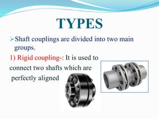

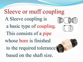


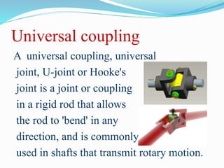
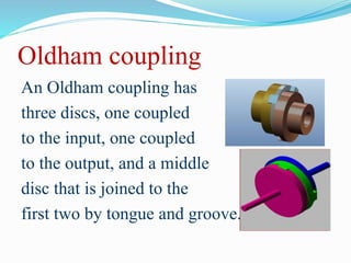


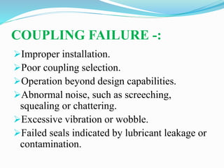


This document discusses different types of shaft couplings, including rigid couplings like sleeve, clamp, and flange couplings as well as flexible couplings like bushed pin, universal, and Oldham couplings. It describes the purpose of couplings in connecting shafts and allowing for misalignment while transmitting motion. Requirements for good shaft couplings include easy connection/disconnection, full power transmission without losses, holding shafts in alignment, and reducing shock loads. The document concludes with information on coupling maintenance through inspection and lubrication and potential failure modes from improper installation or operation beyond design capabilities.