
Recommended
More Related Content
What's hot
What's hot (20)
Similar to Dimapur-Kohima Rail Project Site Visit Report (1).docx
Similar to Dimapur-Kohima Rail Project Site Visit Report (1).docx (20)
Recently uploaded
Recently uploaded (20)
Dimapur-Kohima Rail Project Site Visit Report (1).docx
- 1. Sub.: Report on site visit of officials from Sivok-Rangpo New BG Rail Link Project to tunnel works of Dimapur-Kohima New Rail Link Project Ref.: IRCON/2046/NFR-SRRP/6129 dated 09.05.2023 1. Vide above reference the competent authority of IRCON sent the following five officials from SRRP to tunnel works of Dimapur-Kohima New Rail Link Project to witness and understand the tunnelling works in poor strata (Class VI and VII as encountering there) and for adoption of the same in SRRP also: i. Shri B.C. Karmakar (JGM/C-IRCON) ii. Shri P.C. Dhang (DGM/C/Geology-IRCON) iii. Shri C.K. Prashar (CRE/Amberg) iv. Shri P. Baruah (Geologist/Amberg) v. Shri A. Mannan (Geologist/D2-PEMS) 2. The officials reported to XEN/DMV-NFR and visited the site on 17.05.2023 and 18.05.2023. During which 3 nos. tunnels have been visited, namely, Tunnel T1 P1 and P2 including escape tunnel, Tunnel T4 P1 and P2 and Tunnel T10 P1 and P2 including escape tunnel. The visited tunnels are encountering the worst ground condition in the project where at T1 the encountering class is VI whereas at T4 and T10 the encountering class is VII. 3. The details of observation from each tunnel during the site visit has been given in the tables below: Tunnel T-1 Total length 3490 m Excavated length of P1 and P2 P1- 1897 m and P2- 1057.5 m Construction company M/s ABCI DDC M/s Beaver Infra Consultants Pvt Ltd, Navi Mumbai Rock Support Classes Entirely based on Q-system, however RMR has also been calculated at site for cross-verification Dimension Details Finished Radius:4005mm/ Finished Diameter:8010 mm/Finished Height:7437mm Present support classes P1- Class VI (Q-value 0.07) P2- Class VI (Q-value 0.08) Geological condition (photos in Annex. I) P1: Alternate bands of thick (0.5 to 1.0 m) beds of sandstone and thinner beds of laminated shale. Three prominent joint sets (45/140, 50/310, 60/250). Heavy water ingress. P2: Alternate bands of thick (0.5 to 1.0 m) beds of sandstone and thinner beds of laminated shale. Three prominent joint sets (45/155, 60/030, 60/300). Moderate water ingress. Primary support in following sequence Forepoling 32 mm/4 m/300 mm c/c spacing/SN Method of excavation Drilling & Blasting (full face) Excavated area 70 sq. mt. Pull length 2.25 m Rockbolt 25 mm/6 m Grouted SN or SDR/1 m interval LG 109X16x25, 0.75 m spacing, 3 set in one pull
- 2. Wiremesh 150X150X6, double layer Shotcrete 300 mm (M25) Remarks 1. Invert has been closed therefore; the road condition in tunnel is well maintained. 2. Cycle time ranges from 26-27 hrs in April’23 3. Rock Bolts are installing just after scaling, then ceiling shotcrete and/ primary shotcrete with double layer wire mesh. Advantage: During final lining rock bolt cutting operation is eliminated. Disadvantages: a) Functional/Technical requirement of rock bolt is diluted by installing before primary shotcrete, as it will act like soil nail or spot-bolt. b) Primary shotcrete will get delayed due to grouting operation and waiting until torqueing is completed, which is 12 hours after grouting. Tunnel T1P1, 3490m long having parallel escape tunnel. Support class VI is applied. Method of tunnelling is NATM. During site visit, survey for L.G. erection was in progress. There was no electricity on tunnel face during 40 minutes stay. Muck disposal was completed and survey for L.G. erection was in progress, no face sealing observed, heavy water seepage observed on tunnel face, no face drainage holes observed, SN forepolling was installed. In Tunnel last three/four rounds from tunnel face irregular tunnel shape observed. Tunnel excavation being carried out with drill and blast method in full face. Pull length is fixed for 2.25m. Three set of L.G. installed in one pull of 2.25m at spacing of 0.75m. L.G. spacing can be increased 1m to 1.25m. Rock Bolts installation is at excavated periphery as per GFC Drawings. Main tunnel execution completed without TRNs. TRNs still pending in executed 1897m length. Ventilation and housekeeping observed ok. Tunnel road is well maintained. Tunnel grade is upward. Dewatering is by gravity from middle of tunnel through casted tunnel invert, no side drains inside tunnel, parallel traffic movement is easy which causes lesser time in muck disposal. Execution of work is going on round the clock without losing lunch time and shift change is on running tunnel face. Photos of Tunnel T1P1 attached below. Photo: Tunnel T1P1
- 3. Photo: Tunnel face/No electricity Photo: Irregular tunnel shape on LHS crown
- 4. Photo: No face drainage holes/Installed forepolling Photo: Irregular TRN Profile where ISMB RIB were in progress. Tunnel T-4 Total length 1168 m Excavated length of P1 and P2 P1- 678.5 m and P2- 49.5 m Construction company M/s BIPL DDC M/s Beaver Infra Consultants Pvt Ltd (Design), M/s Progressive Machine Tools (PMT) (Supervision) Rock Support Classes Based on RMR and cross-verification by Q-value Present support P1- Class VII (Q-value 0.0091, RMR 18)
- 5. classes P2- Class VII (Q-value 0.0031, RMR 16) Geological condition (photos in Annex. I) P1: Dominantly laminated shale with subordinate thin beds of sandstone. Three prominent joint sets (38/098, 65/152, 73/305). Slightly damp ground. P2: Thinly laminated shale, highly weathered. Three prominent joint sets (43/050, 65/205, 72/103). Damp ground. Primary support in following sequence Forepoling 32 mm/4 m/200 mm c/c spacing/SN Excavation method Mechanical breaking (Heading-Benching-Invert)/Drilling blasting Excavated area 69.64 sq. mt. Pull length P1: 2.25-3 m P2: 1 m Rockbolt NA Ribs ISMB 250X125 @ 0.75 m spacing, 3 set in one pull Lagging MS plate 6 mm (or slabs 730X200X50 Backfilling M20 Primary lining thickness 450 mm Remarks 1. Support is Rigid and Conventional 2. Cycle time 20-22 hrs avg. 3. Lesser activities in each cycle: (a) Face excavation for heading,(With Blasting operation) (b) Scaling and mucking, (c) Face sealing, (d) Surveying and placement of steel support, (e) Erection of ISMB, (f) Backfilling, (g) Anchor drilling and fixing with SN type, no SDA rockbolt, hence, time savings for grouting and torqueing etc, however, for such worst rock class, where, hole collapse situation, design permitted for SN Rock Bolt anchoring of RIB with Plate. (f) Out of alternate 3 RIB spacing @0.75 mtr for one RIB spacing 3.14mm MS plate is at Tunnel Side of RIB (Inner) and for 3 RIB space plates are welded with RIB outer side, thus less concrete back filling, Remaining 3 round space backfilling will be done along with final lining, thus less time for round length. Tunnel T4P1, 1168m long. Method of Tunnelling is conventional. Support class VII is applied. Side slope in front of portal are damaged. During site visit backfilling concrete for benching was in progress. Tunnel face in dry condition hence no water seepage observed in executed tunnel, no drainage holes was drilled. Tunnel excavation carried out by mechanical/Drill and blast method in Heading/Benching and Invert. Excavated benching face, some blasting drilled holes sockets observed. Tunnel face muck is being used for maintenance of tunnel road. SN type forepolling is in use. Heading pull length is fixed for 2.25m. Three set of Ribs 150 X 250mm ISMB were installed in one pull at spacing of 0.75m. Maximum achieved monthly progress 40m. Ribs spacing can be increased 1m to 1.25m. Out of alternate 3 RIB spacing @0.75 m for one RIB spacing 3.14mm MS plate shuttering is at Tunnel Side of RIB Inner flange and for 3 RIB space plates are welded with RIB outer flange, thus less concrete back filling, Remaining 3 round space backfilling will be done along with final lining, thus less time for round length. Ventilation and housekeeping is ok. Tunnel road is well maintained. Main tunnel execution completed without TRNs. TRNs still pending in executed 679m length. Methane gas is encountered in tunnel; additional ventilation fan is located inside tunnel to dilute encountered
- 6. methane gas. Execution of work is going on round the clock without losing lunch time and shift change is on running tunnel face. Photos of Tunnel T4P1 attached below. Photo: Damaged side slopes/No rock bolts
- 7. Photo: Damaged side slopes/No rock bolts Photo: Tunnel T4P1/Good road condition inside tunnel
- 8. Photo: Benching concrete pouring Photo: Tunnel heading face/Dry conditions
- 9. Photo: Shuttering at Inner and Outer flange of Ribs Photo: Installed SN forepolling
- 10. Photo: Tunnel muck is used for road maintenance Photo: Sockets of drilled blasting holes at benching face
- 11. Photo: Excavated benching face Tunnel T4P2, Method of Tunnelling is conventional. Support class VII is applied. Side slope in front of portal are damaged. During site visit no activity at tunnel face. Tunnel work is stopped for maintenance of approach road of tunnel to work in rainy season. Tunnel face in dry condition hence no water seepage observed in executed tunnel, no drainage holes was drilled. Tunnel excavation carried out by mechanical method in Heading/Benching and Invert. One set of Ribs 250mm ISMB are installed in one pull at spacing of 1.00m. Maximum achieved monthly progress 12m. Out of alternate 3 RIB spacing @0.75 m for one RIB spacing 3.14mm MS plate shuttering is at Tunnel Side of RIB Inner flange and for 3 RIB space plates are welded with RIB outer flange, thus less concrete back filling, Remaining 2 round space backfilling will be done along with final lining, thus less time for round length. Housekeeping is ok. Tunnel road is well maintained. Execution of work is going on round the clock without losing lunch time and shift change is on running tunnel face. Photos of Tunnel T1P2 attached below.
- 12. Photo: Tunnel T4 Portal 2 Photo: Damaged side slopes/No rock bolts
- 13. Photo: Damaged side slopes/No rock bolts Photo: Tunnel Heading face/Dry conditions
- 14. Photo: Shuttering on Inner and Outer flange of Rib Tunnel T-10 Total length 5889 m Excavated length of P1 and P2 P1- just started and P2- 97 m Construction company M/s ABCI PMC M/s AECOM Rock Support Classes Based on Q-system Present support classes P2- Class VII (Q-value 0.005) or portal class Geological condition (photos in Annex. I) P2: Thinly laminated shale, highly weathered. Four prominent joint sets (25/080, 60/025, 75/315, 45/170). Damp ground. Primary support in following sequence Piperoofing 114 mm/12 m/300 mm c/c spacing Excavation method Mechanical breaking (Heading-Benching-Invert) Excavated area Pull length P2: 0.8 to 1.6 m Ribs ISMB 250X125 @ 0.80 m spacing, 1 or 2 set in one pull Shotcrete 300 mm Wiremesh Double layer Rockbolt Only on walls 4 nos./ 8 nos. in benching Remarks 1. Support is by NATM 2. Cycle time 16 hours for heading 3. 114 mm pipe roofing incl. grouting in about 30 hrs
- 15. Advantages: a) With the 114 mm pipe roofing, crown damage is being eliminated from water jet impact during 76mm SDA pipe roof operation. b) Rock Bolting at crown pipe roofing area is avoided being it is difficult and damage of pipe roof, uncertainty of vacant space for insertion of rock bolt, thus cost & time savings for rock bolting operation. c) For 12 m Pipe Roofing continuous 9 m progress can be achieved for each 12 m round of pipe roofing. 4. Rock Bolts are installing just 1st layer of shotcrete and then double 2nd layer wiremesh with shotcrete. Advantage: During final lining rock bolt cutting operation is eliminated. Disadvantages: Due to grouting operation and waiting until torquing is completed, which is 12 hours after grouting 2nd layer shotcrete will get delayed.. Tunnel T10P2, 5889m with parallel Escape tunnel. Method of Tunnelling is NATM. Support class VII (Q-system) is applied. Tunnel 10 Portal 2 execution work was started in December 2022, 92 m tunnel execution done till date. During site visit face sealing shotcrete to start at tunnel face. Tunnel face in partial damp condition. Tunnel excavation carried out by mechanical method in Heading/Benching and Invert. Pull length is fixed for 0.8m to 1.6m as per site conditions. One/Two set of Ribs 150 x 250mm ISMB are installed in one pull at spacing of 0.80m. Maximum achieved monthly progress 25m. No Bi-reflex 3D monitoring targets installed in around 29m of executed heading. Housekeeping is ok. Tunnel road is well maintained. Pipe roofing umbrella of 114mm seamless pipes 45 numbers 12m long with grouting were installed in 32/33 hours by operating in both booms of boomer. Rock bolts are installed after first layer of shortcrete. Execution of work is going on round the clock without losing lunch time and shift change is on running tunnel face. Photos of Tunnel T10P2 attached below.
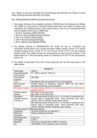
- 16. Photo: Tunnel T10 Portal 2 Photo: Face sealing shotcrete to start
- 17. Photo: Tunnel heading face/Partial Damp conditions
- 18. Photo: No 3D monitoring targets installed 4. The rock support classes of Dimapur-Kohima Rail Link Project are different from that of SRRP. In SRRP also the Q-system and RMR have been adopted, however, they are further modified as per the ground condition and their behaviour in Darjeeling-Sikkim Himalaya. Whereas, in DKP, the standard classification system of Barton’s Q-value has been adopted by designer of T1 and T4, i.e., M/s Beaver. Even the supporting elements in each rock support class of Beaver for T1 and T4 are based on Barton’s system with slight modifications. Though the Q-value system has been adopted by M/s AECOM at T10 of DKP, but again further sub-classification has been done in between. And the supporting elements of each rock support class of AECOM for T10 are based on NATM and not on Barton’s Q-system. The detail comparison of each approach of rock support classification has been given below.
- 19. Standard Rock Mass Classification SRRP DKP D2-PEMS (T1-T2) D2-PEMS (T9-T10) AECOM (T3-T6) AMBERG (T7-T8 & T11-T14) BEAVER (T1) BEAVER (T4) AECOM (T10) RMR (Beniawski) Q-value (Barton) RMR Rock Support Classes (Types) RMR/GSI (GSI=RMR'- 5) Rock Support Classes (Types) RMR Rock Support Classes Q-value Rock Support Classes Q-value Rock Support Classes RMR Rock Support Classes Q-value Rock Support Classes 0-20 Very poor 0.001- 0.01 Exceptionally poor <20 6 GSI 20-25 6 <20 G 0.001- 0.01 VI 0.001- 0.01 VII <20 VII 0.001-0.01 VII 0.01-0.1 Extremely poor 0.01-0.1 V 0.01-0.1 VI 0.01-0.05 VI-B 0.05-0.1 VI-A 21-40 Poor 0.1-1.0 Very poor 21-40 5 GSI 25-35 5 21-30 F 0.1-1.0 IV 0.1-1.0 V 0.1-0.5 V-B 31-40 E 0.5-1.0 V-A 41-60 Fair 1.0-4.0 Poor 41-50 4 GSI 35-40 4 41-50 D 1.0-4.0 III 1.0-4.0 IV 51-60 3 GSI 40-45 3 51-60 C 61-80 Good 4.0-10.0 Fair 61-80 2 _ 2 61-75 B 4.0-10.0 II 10.0-40.0 Good >75 A >10 I 81- 100 Very good 40.0- 100.0 Very good 81-100 1 _ 1 _ _ _ _ 100.0- 400.0 Extremely good >400.0 Exceptionally good