Download as PDF, PPTX
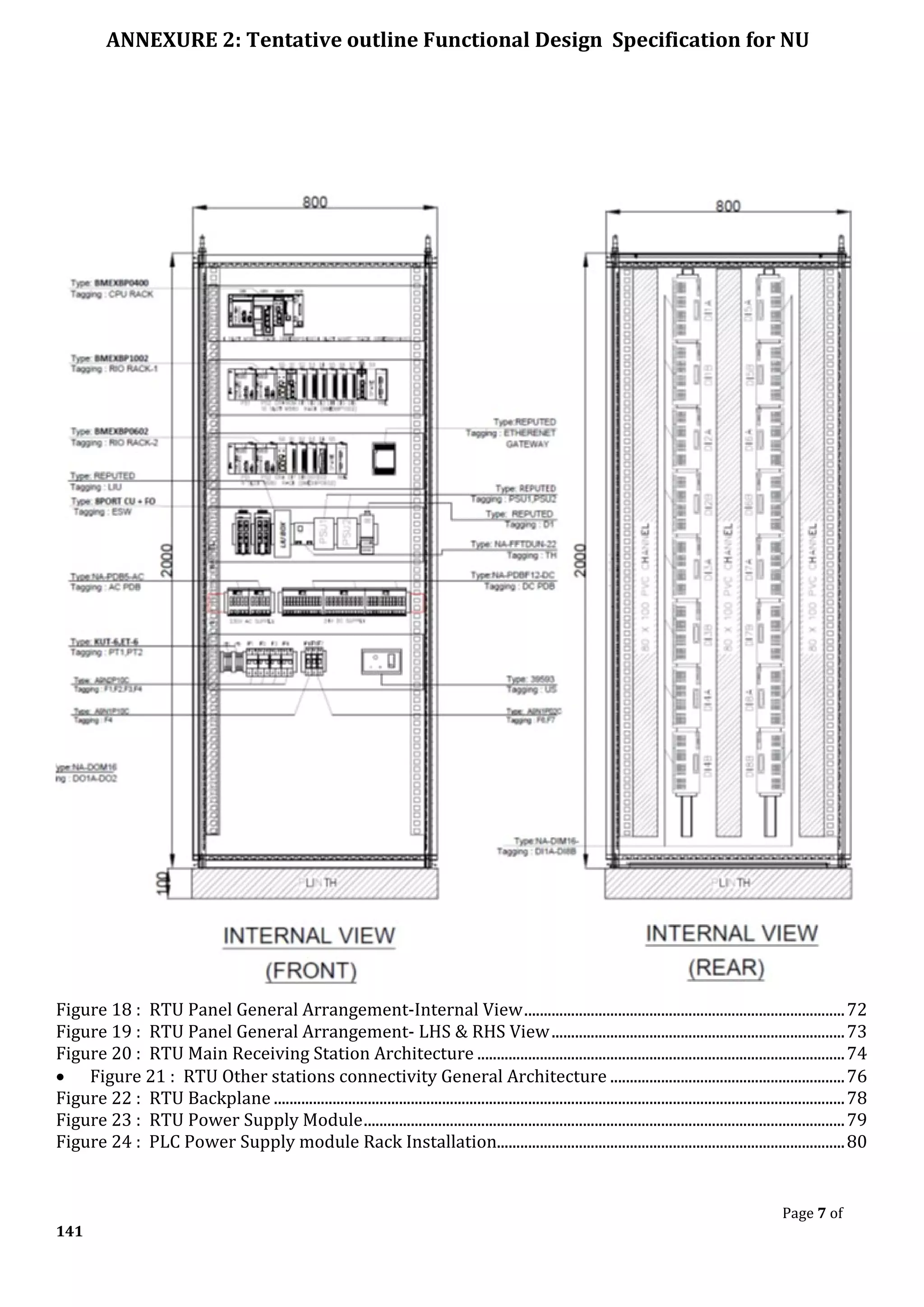

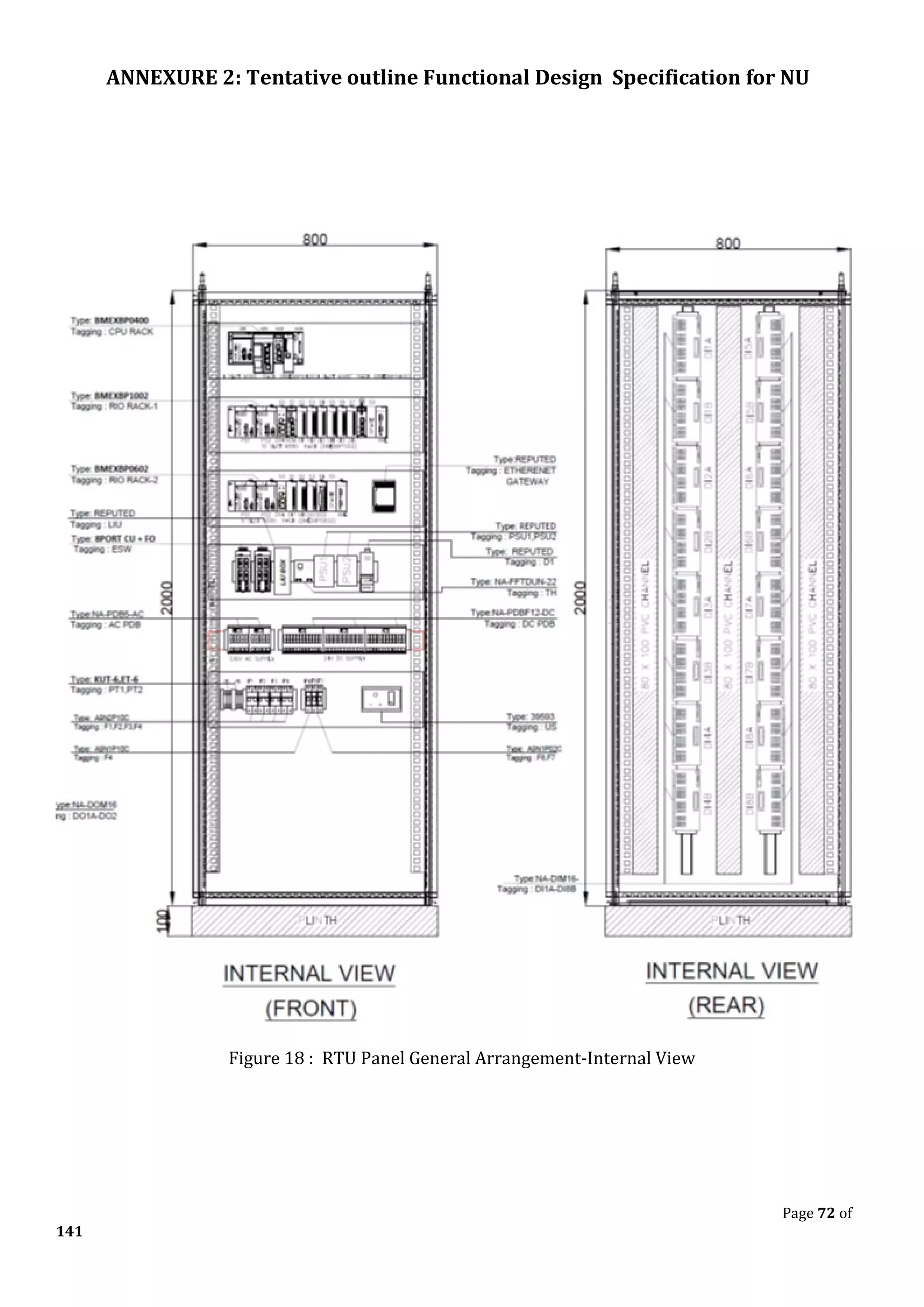
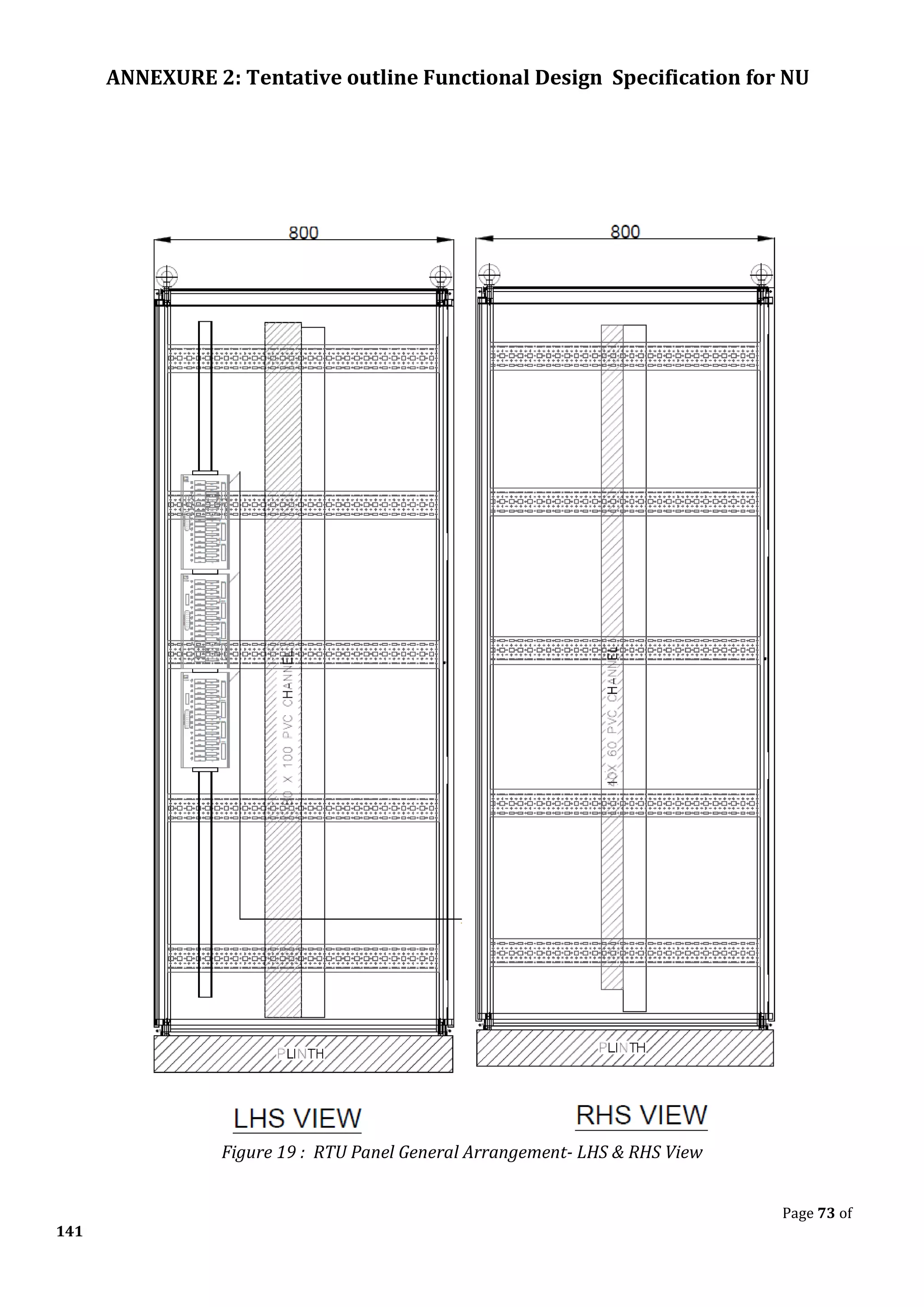
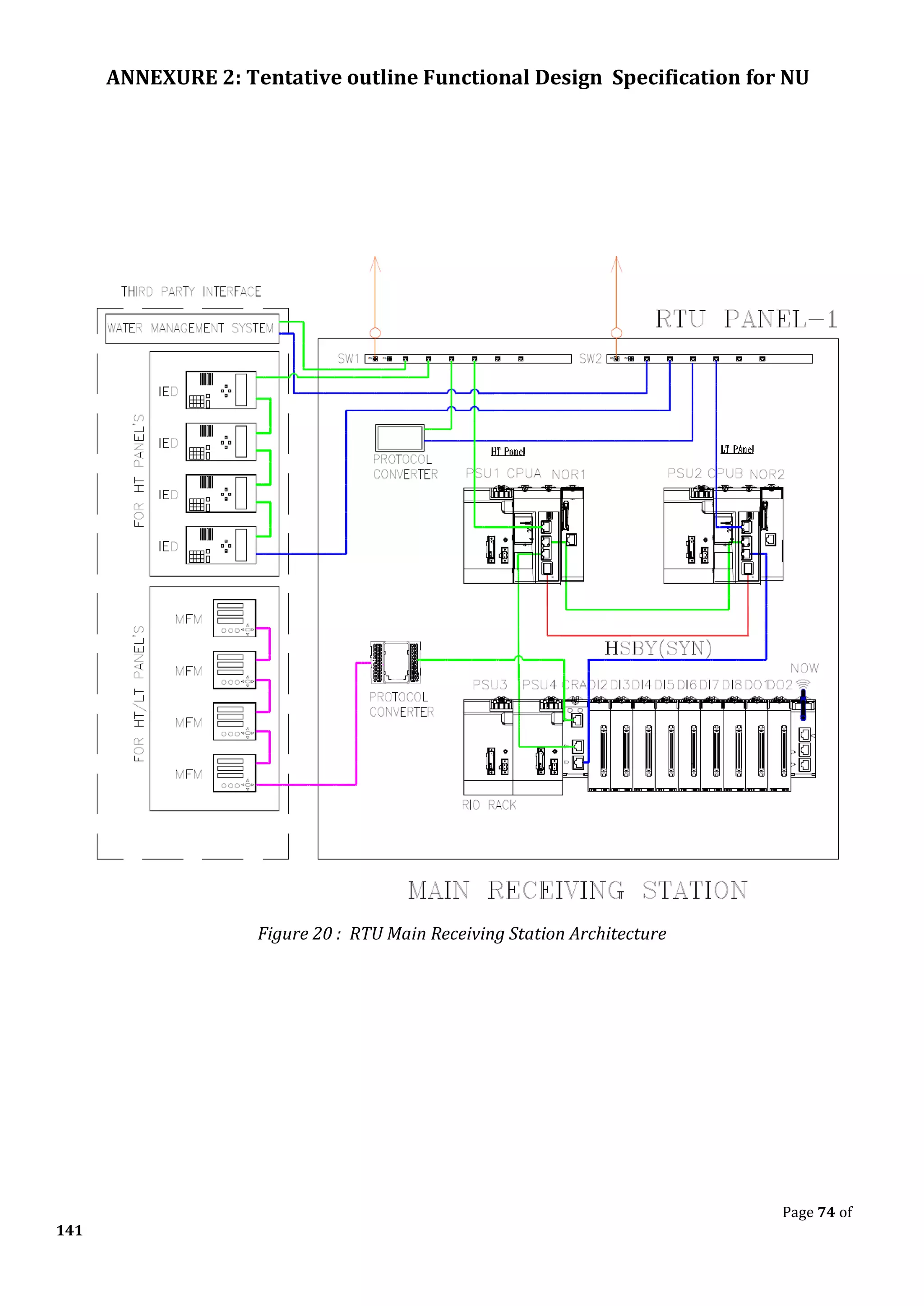
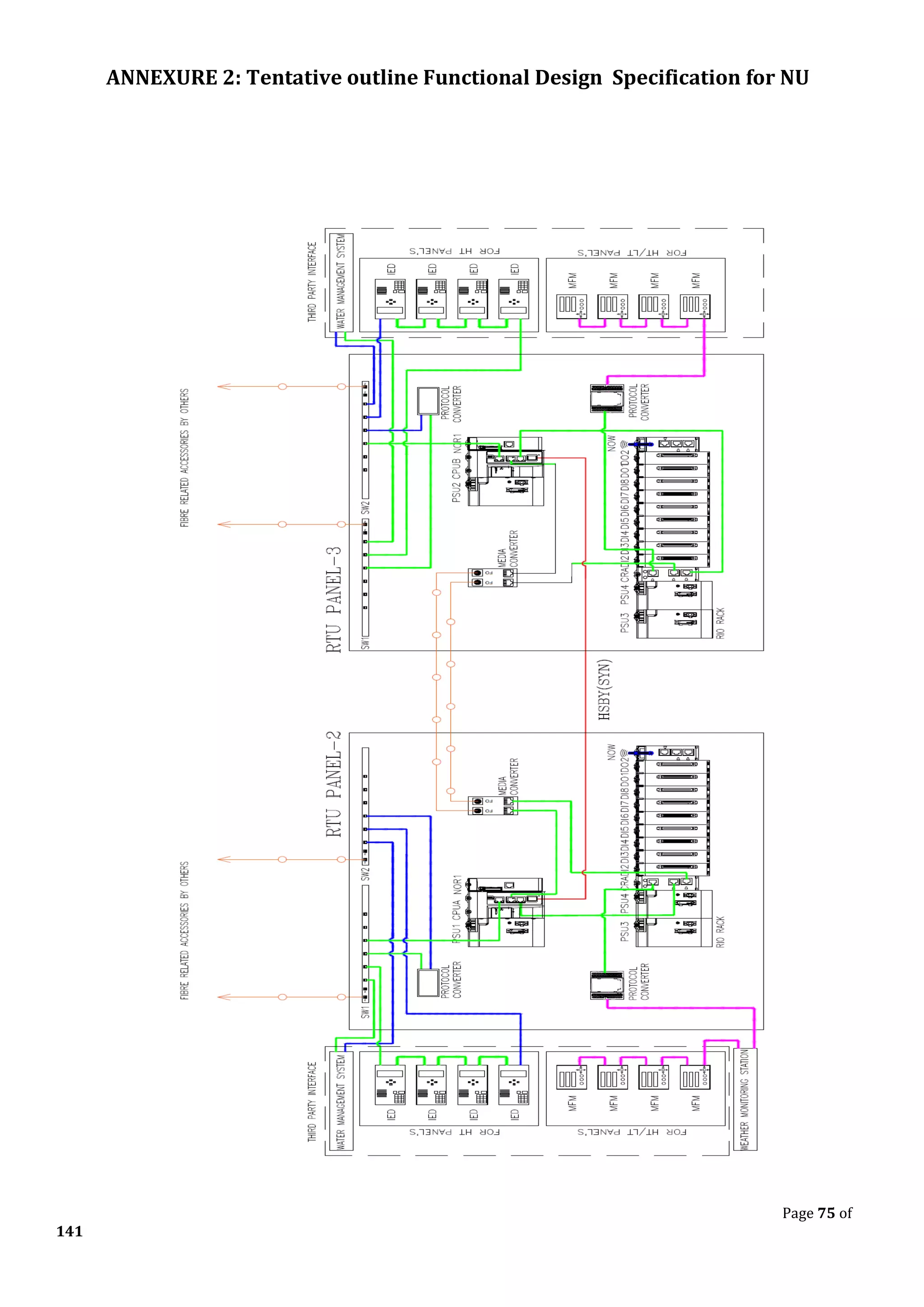
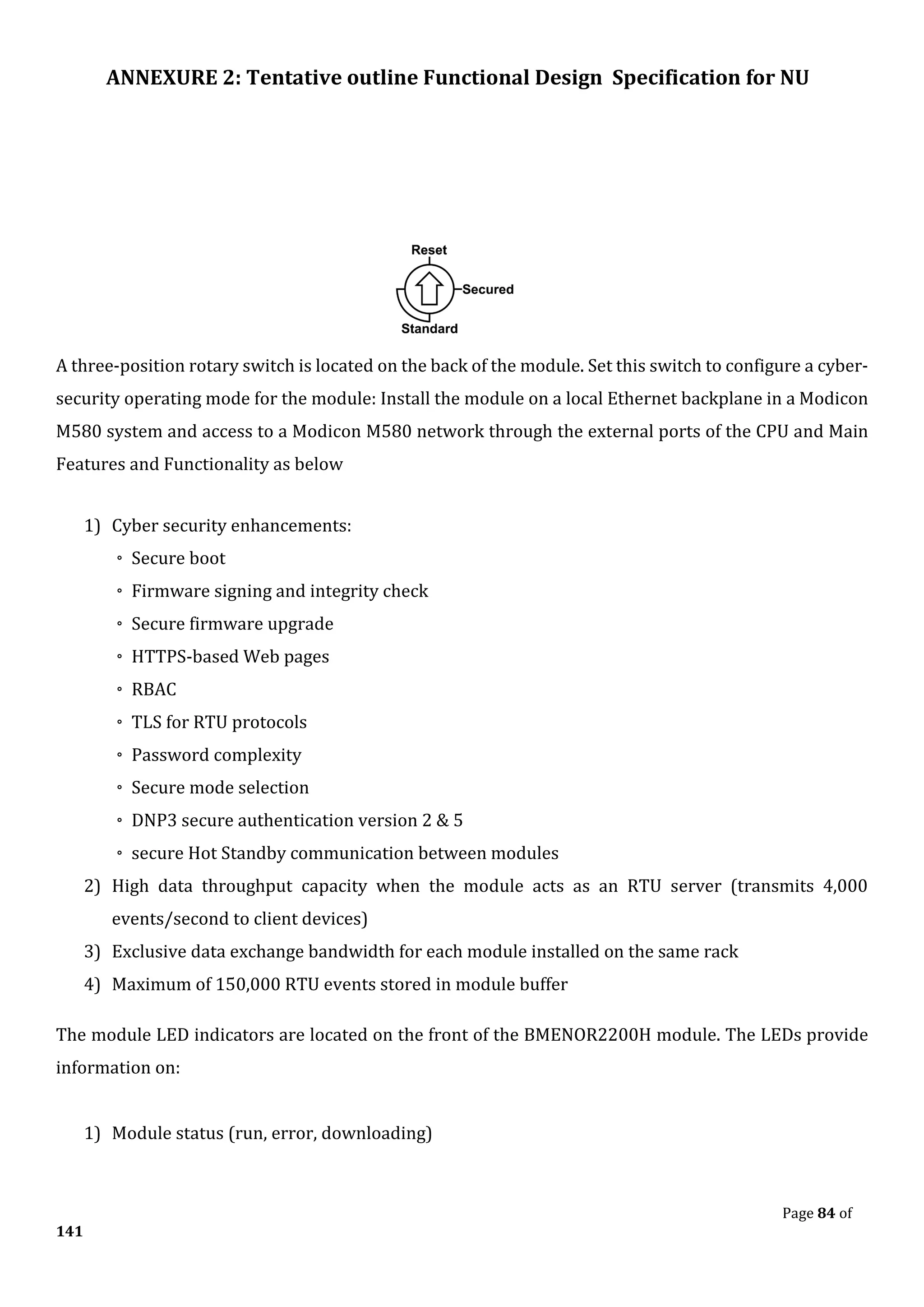
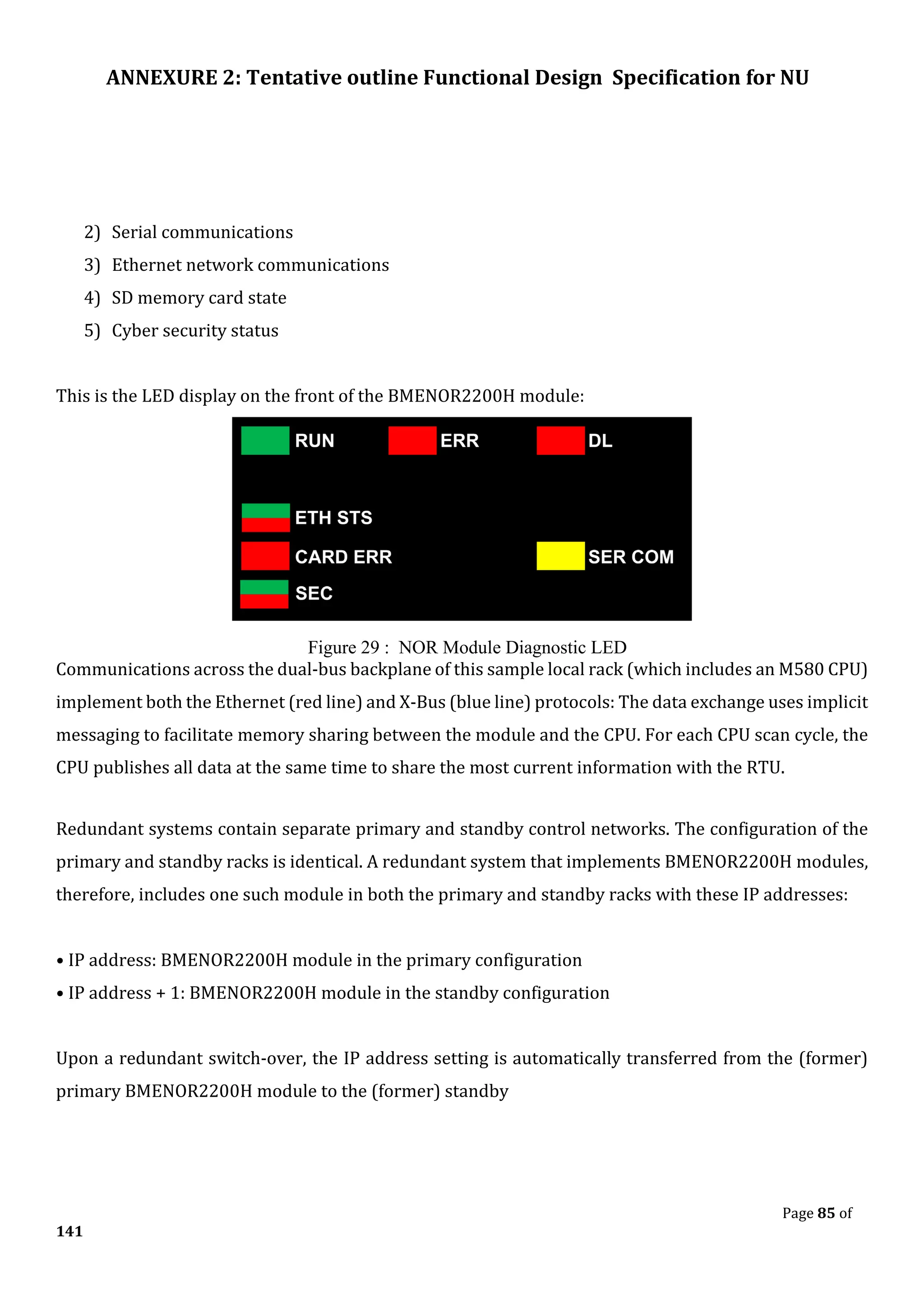
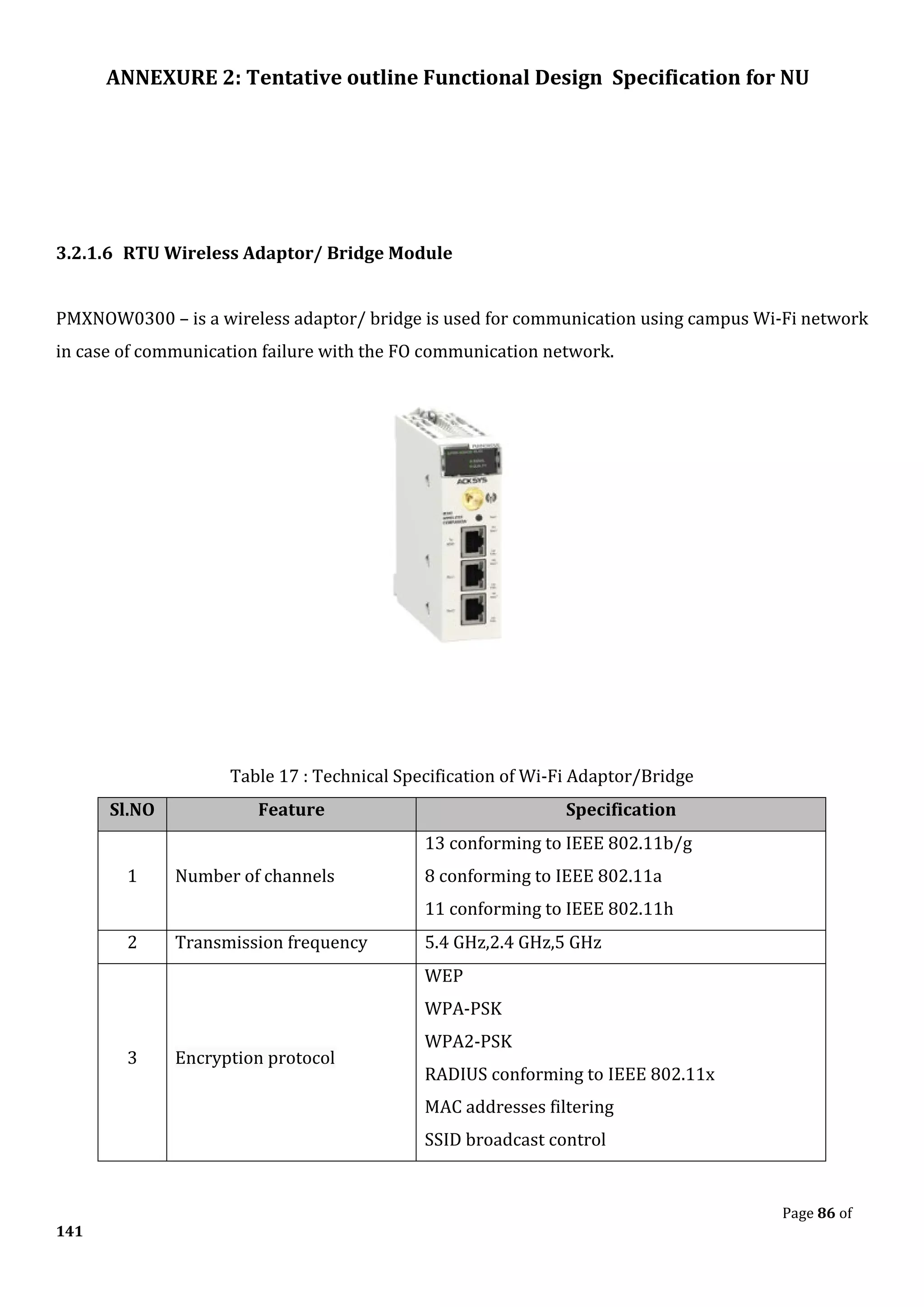
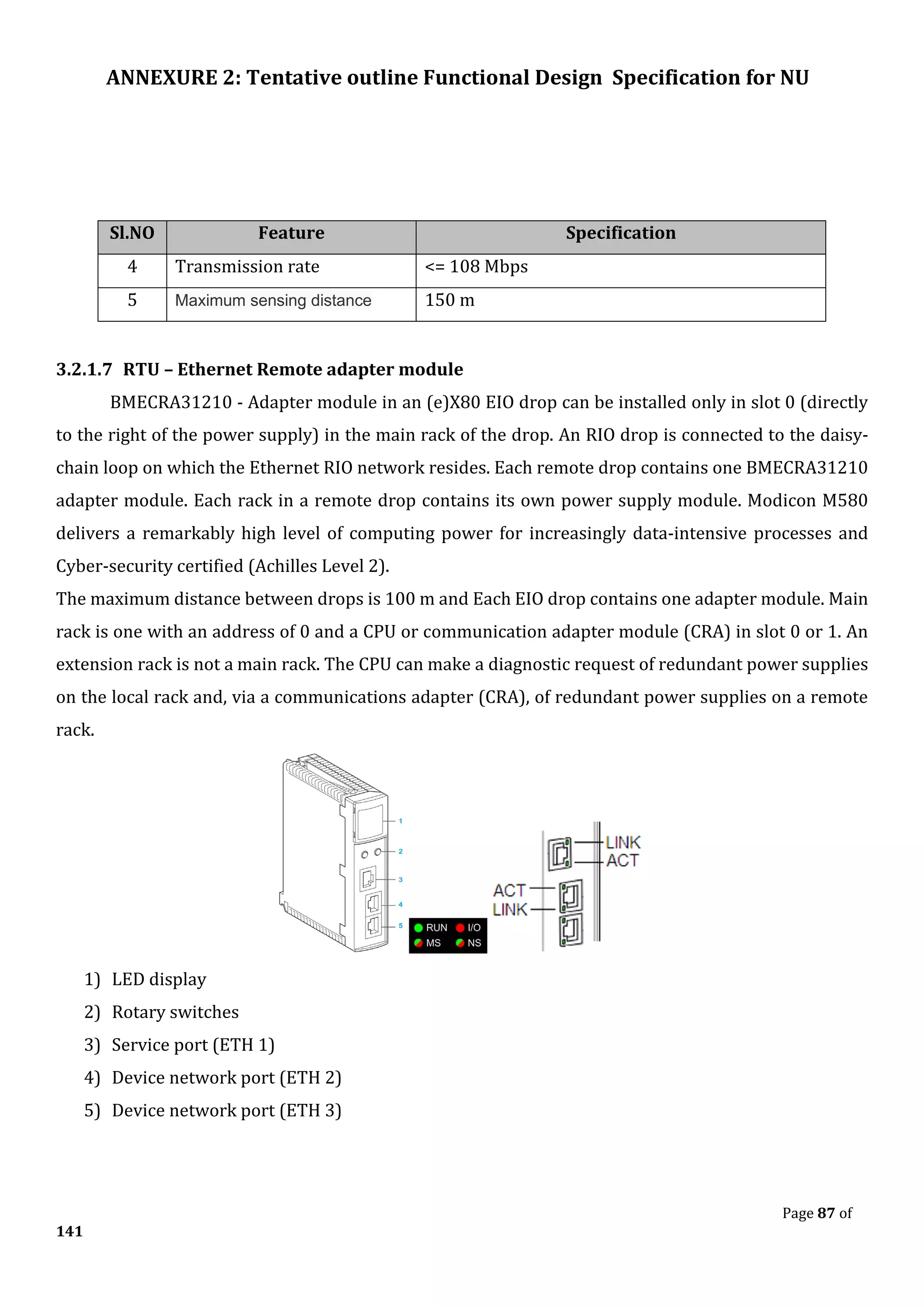

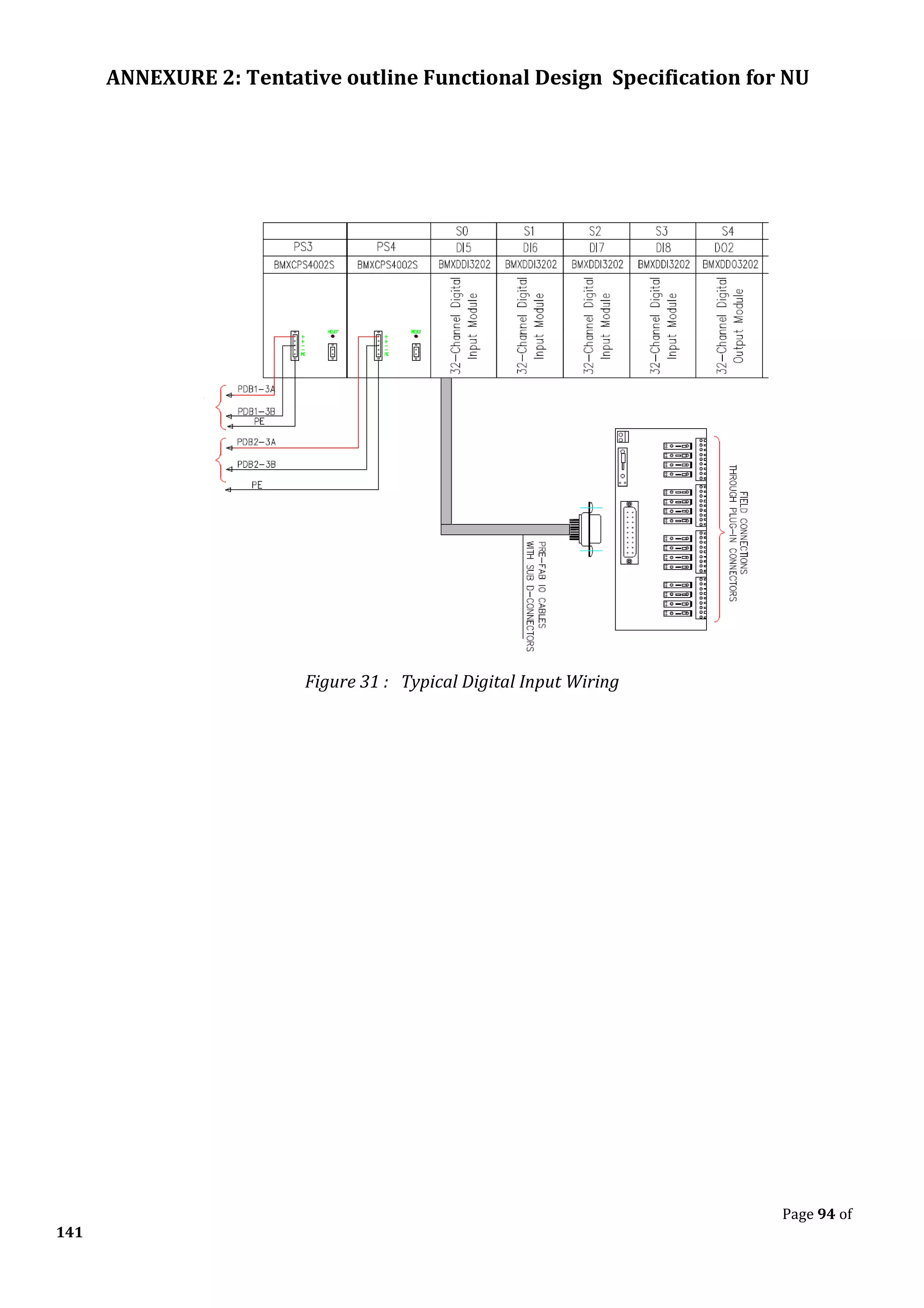
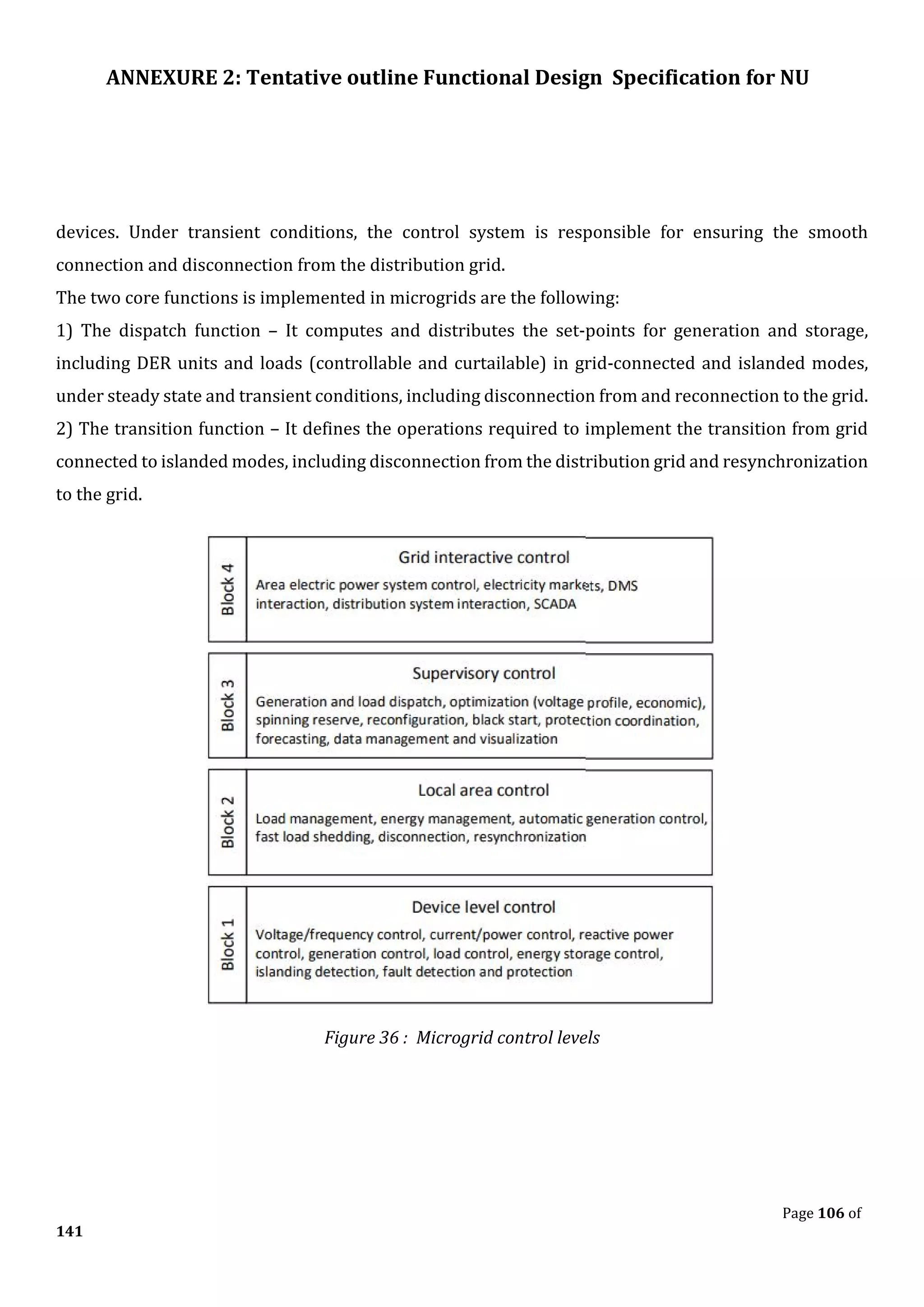
![ANNEXURE 2: Tentative outline Functional Design Specification for NU
Page 136 of
141
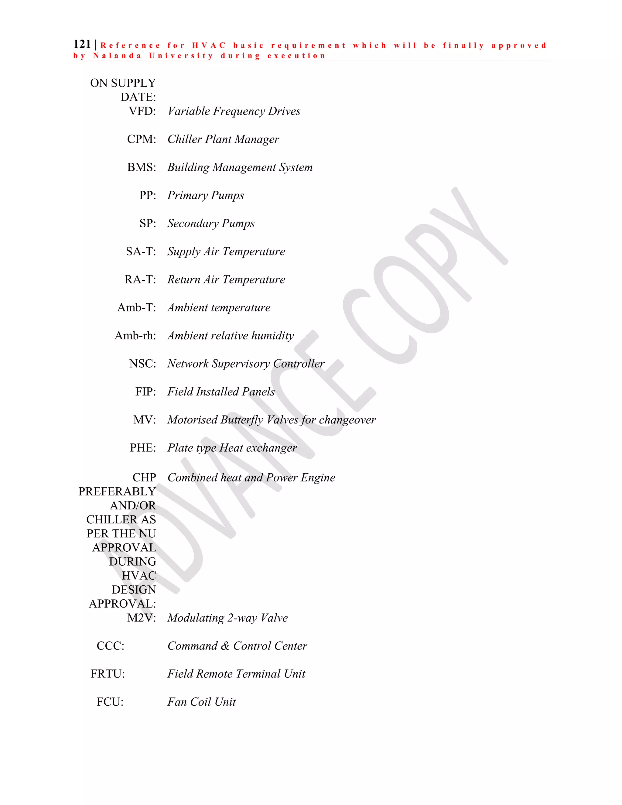
8.4.3 System Architecture- to be designed by ECP contractor as per
the Net-Zero Campus Requirement which will be further
reviewed and approved by NU.
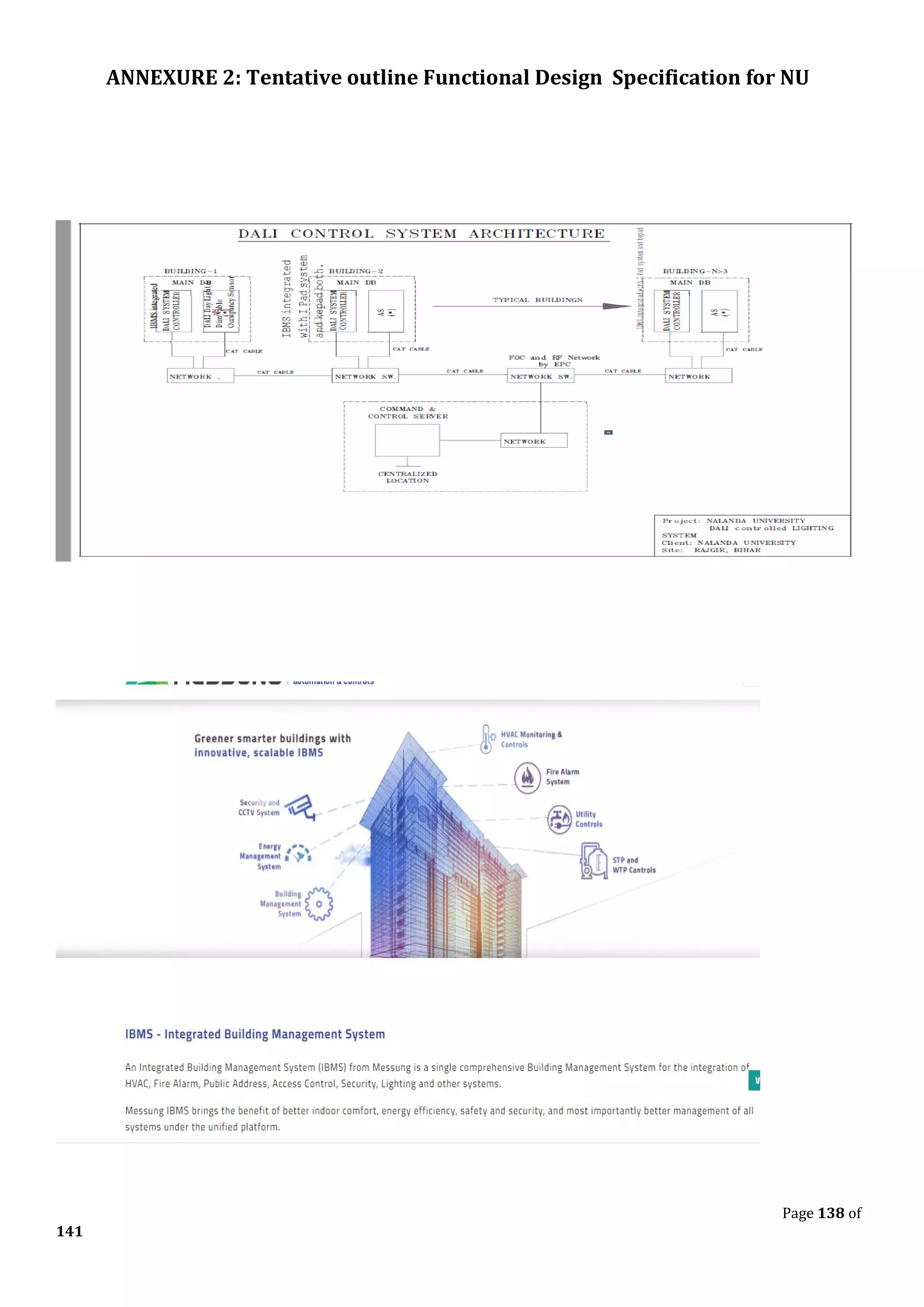
8.5 DALI System for automatic Lighting control and monitoring system
–
Design Supply, Store, Shifting, Installation, Testing & Commissioning of following DALI based lighting
control system including required all misc accessories & supporting items. Components are given below
(Note for all DALI related items: This includes providing system architecture for approval as per OEM
system requirement; the successful bidder has to co-ordinate for DALI system installation with existing
contractor concerned at the site and in case of any fail, the successful bidder of this DALI system will be
sole responsible for its execution without any extra cost.) All equipment’s shall have 50% spare capacity
for future usage.
Design Supply, Store, Shifting, Installation, Testing & Commissioning of DIN Rail Infusion Controller.
Ethernet enabled / Plug-and-play design / adequate RS-232 ports / RS-485 ports / 120 low voltage stations
/ Clips on 35mm DIN rail / Built-in USB port / SD Memory Card /Extremely fast processor /Runs on
upgradeable internal software. Should have in built access over internet for trouble shooting, maintenance,
firmware upgrades and updates. Adequate size of factory fabricated lockable enclosure to house
Controller & all other required hardware like power supply, gateway etc shall be included in this item,
having double door & at least IP43 rating.
Design Supply, Store, Shifting, Installation, Testing & Commissioning of suitable range Power Supply unit DIN rail
mount / Convection cooling / Maximum station integration (atleast 120 wireline and 60 Ethernet bus stations).
Design Supply, Store, Shifting, Installation, Testing & Commissioning of Dali Gateway to hook up the local DALI
network on IP for further connectivity to central server via OFC ring. Clips on to a 35-mm DIN rail Max. Dali : 64
Ballast.
Supply, Store, Shifting, Installation, Testing & Commissioning of Station bus cable. Two conductors / Free topology
/ No polarity / Max 90pF/m and approx. Diameter 1.5mm²
Design Supply, Store, Shifting, Installation, Testing & Commissioning of KNX cable as reuired to connect DALI
controllers to key pad sensors etc made of Copper, bare class1 conductor with PVC Insulation, twisted cores in star
quads PVC outer sheath, rated voltage 300 V, testing voltage 4000V, Insulation resistance shall be ≥ 100 MΩ/km,
8X Bending radius fixed & Min. bending radius moved as 15X Working temp fixed min/max [C] : -30°C up to +70 &
Working temp moved min/mac [C] : -5°C up to +50 Burning behavior shall be as per: VDE 0482-332-1-2/IEC 60332-
1: flame-retardant and self extinguishing.
Makes shall be from Hager, Lapp, Helu Kable / equi](https://image.slidesharecdn.com/io-summary-for-ibms-service-230411055348-b48923a6/75/IO-Summary-for-IBMS-Service-pdf-173-2048.jpg)
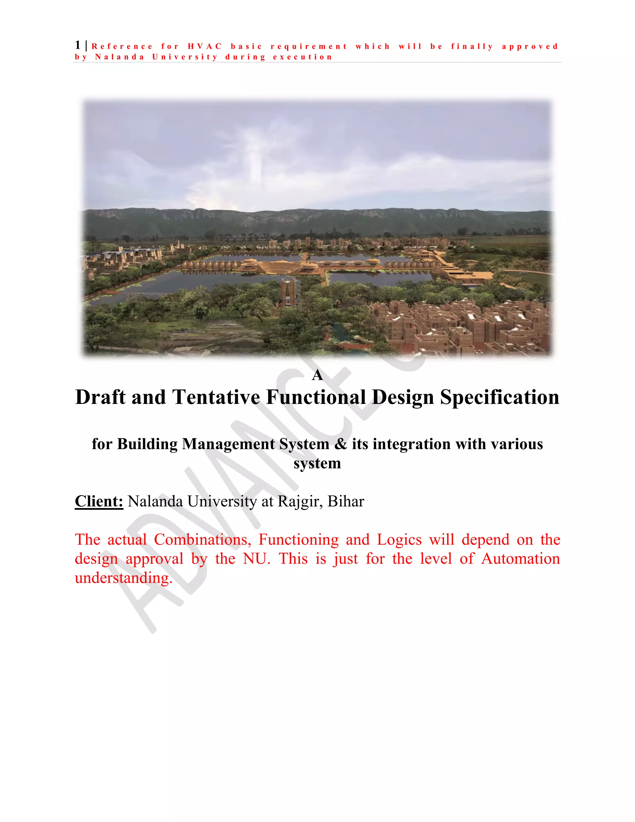
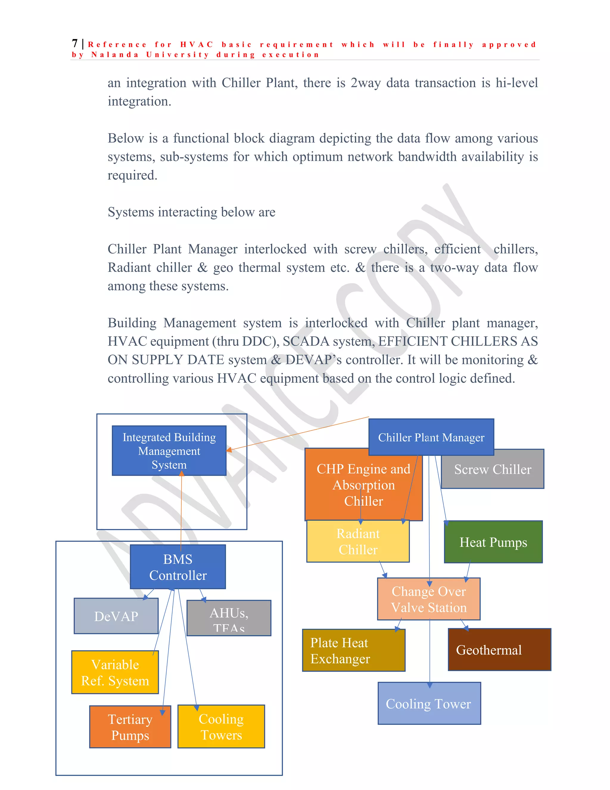


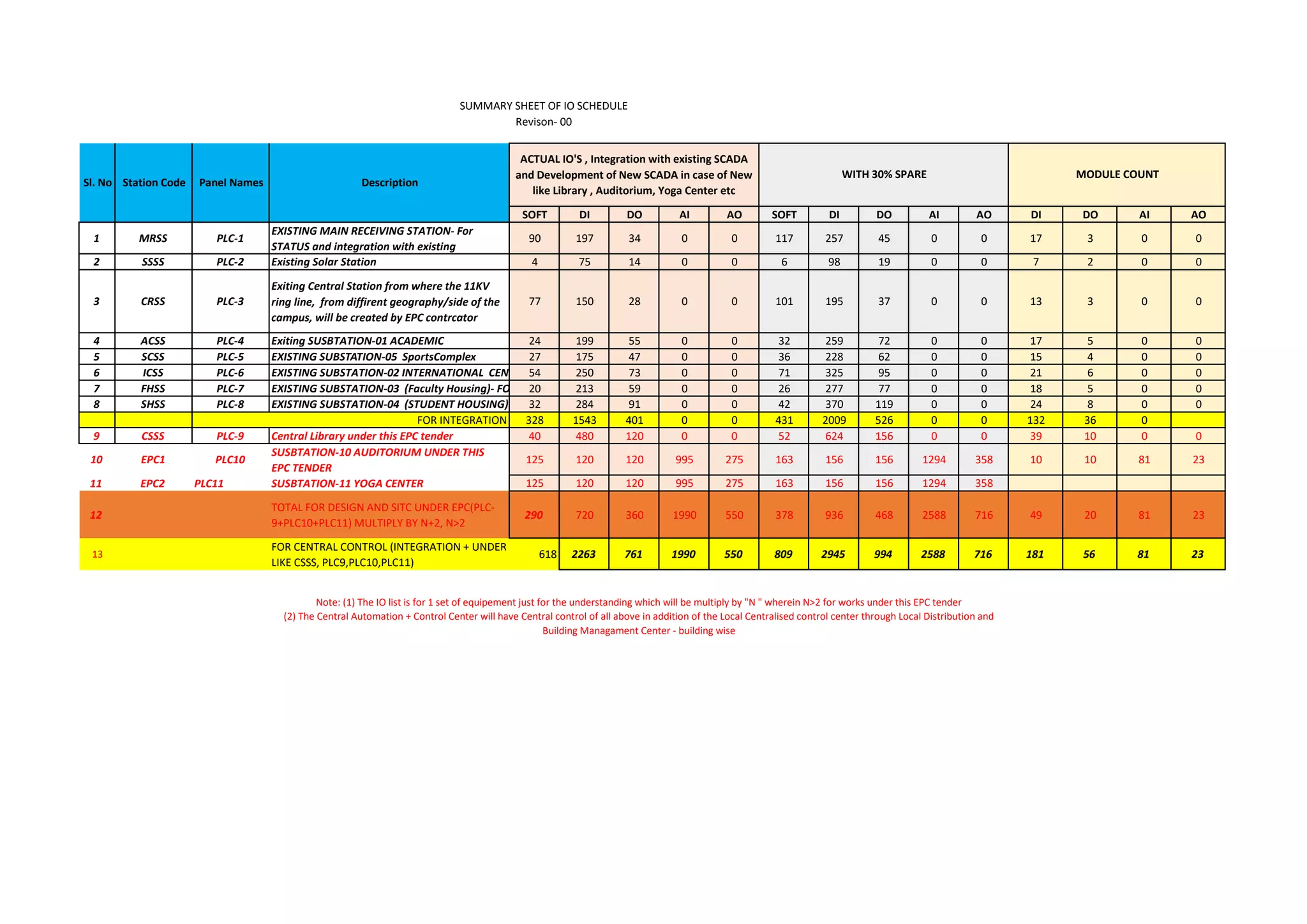
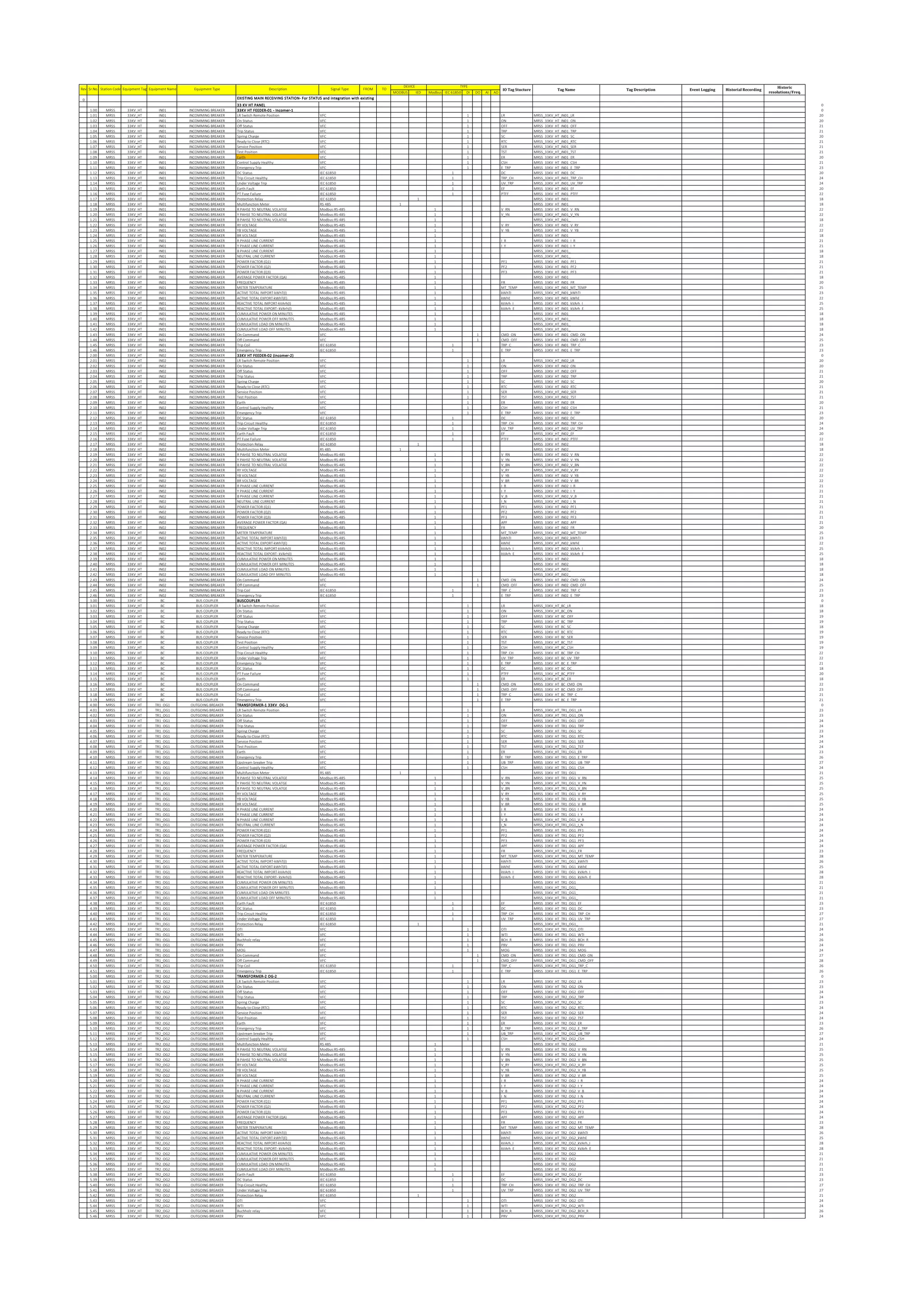
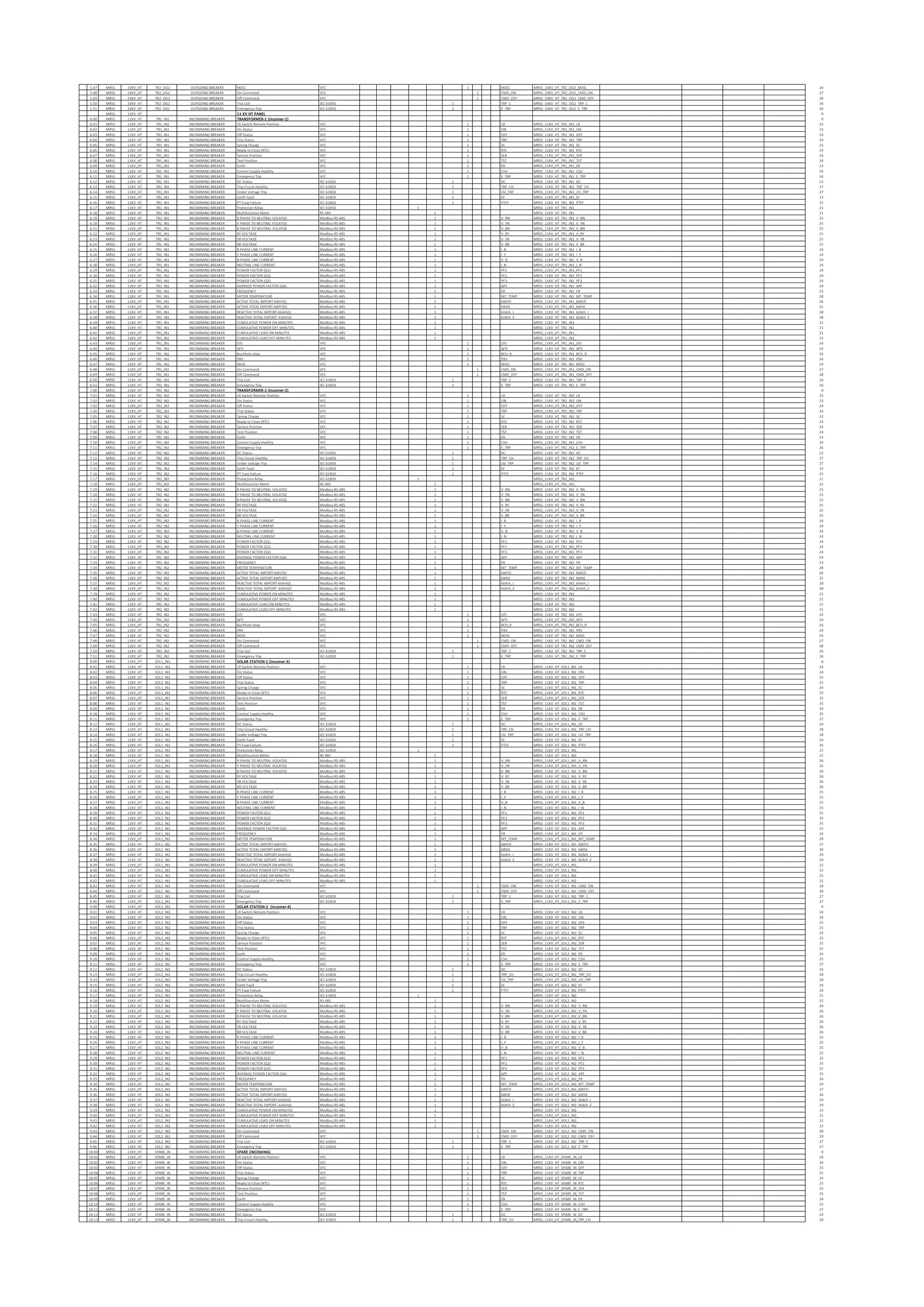
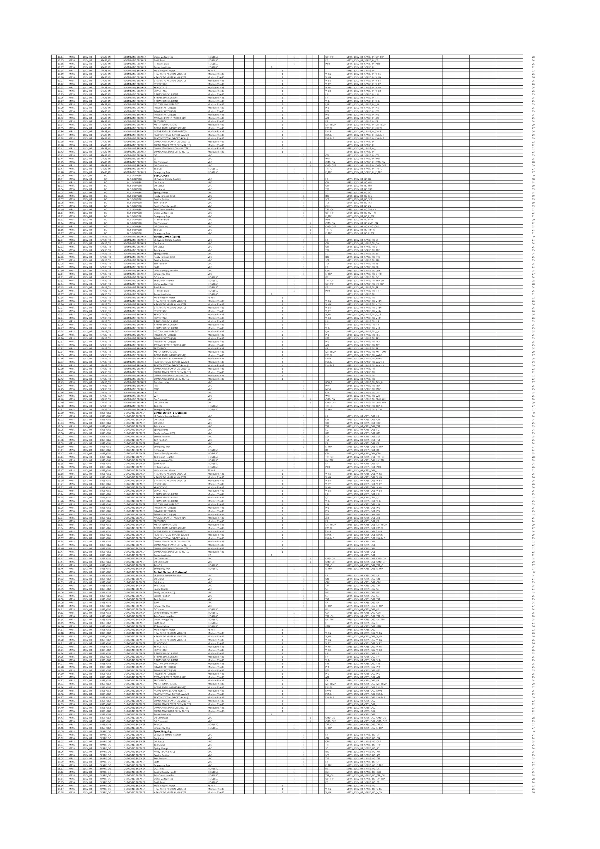
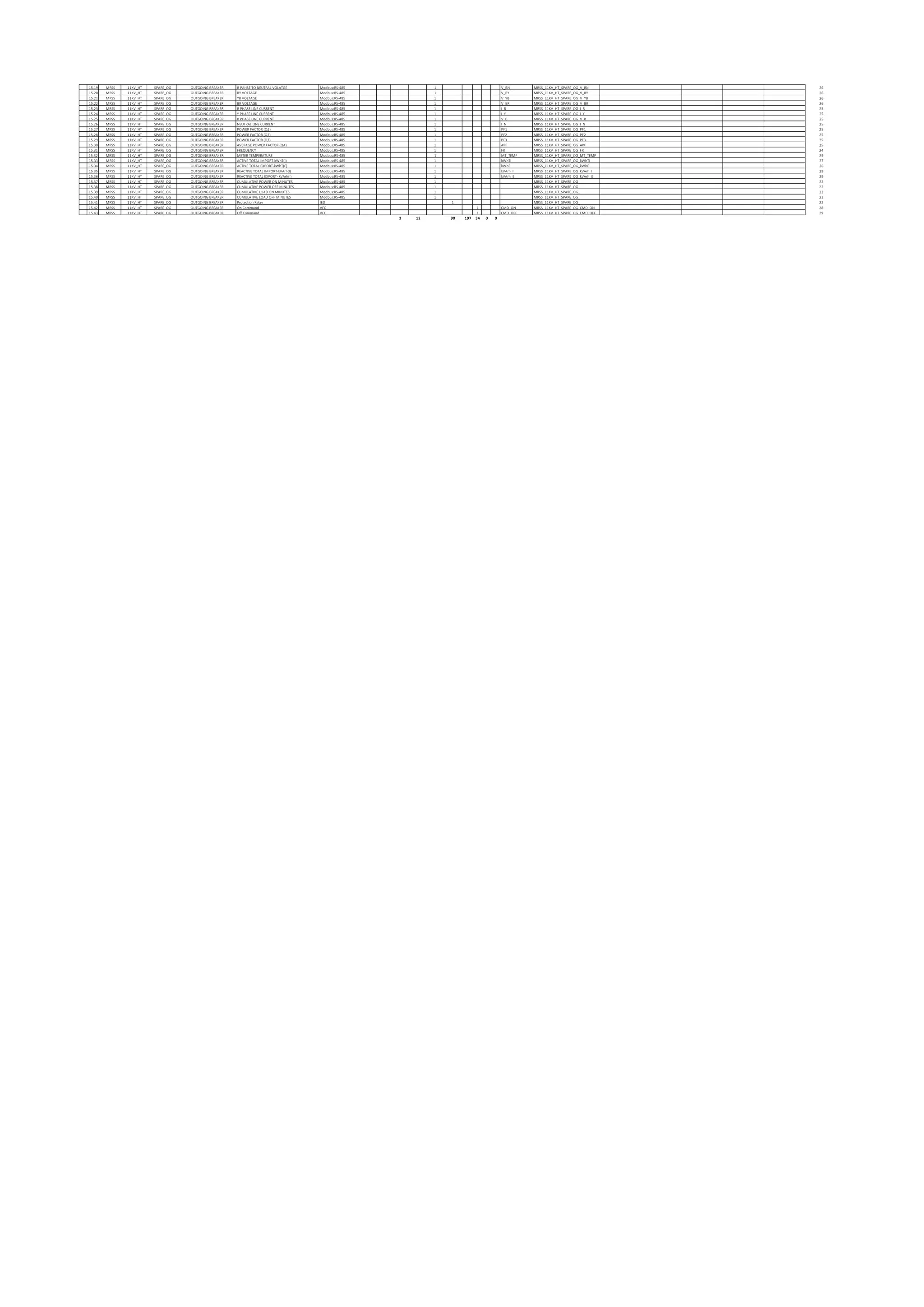
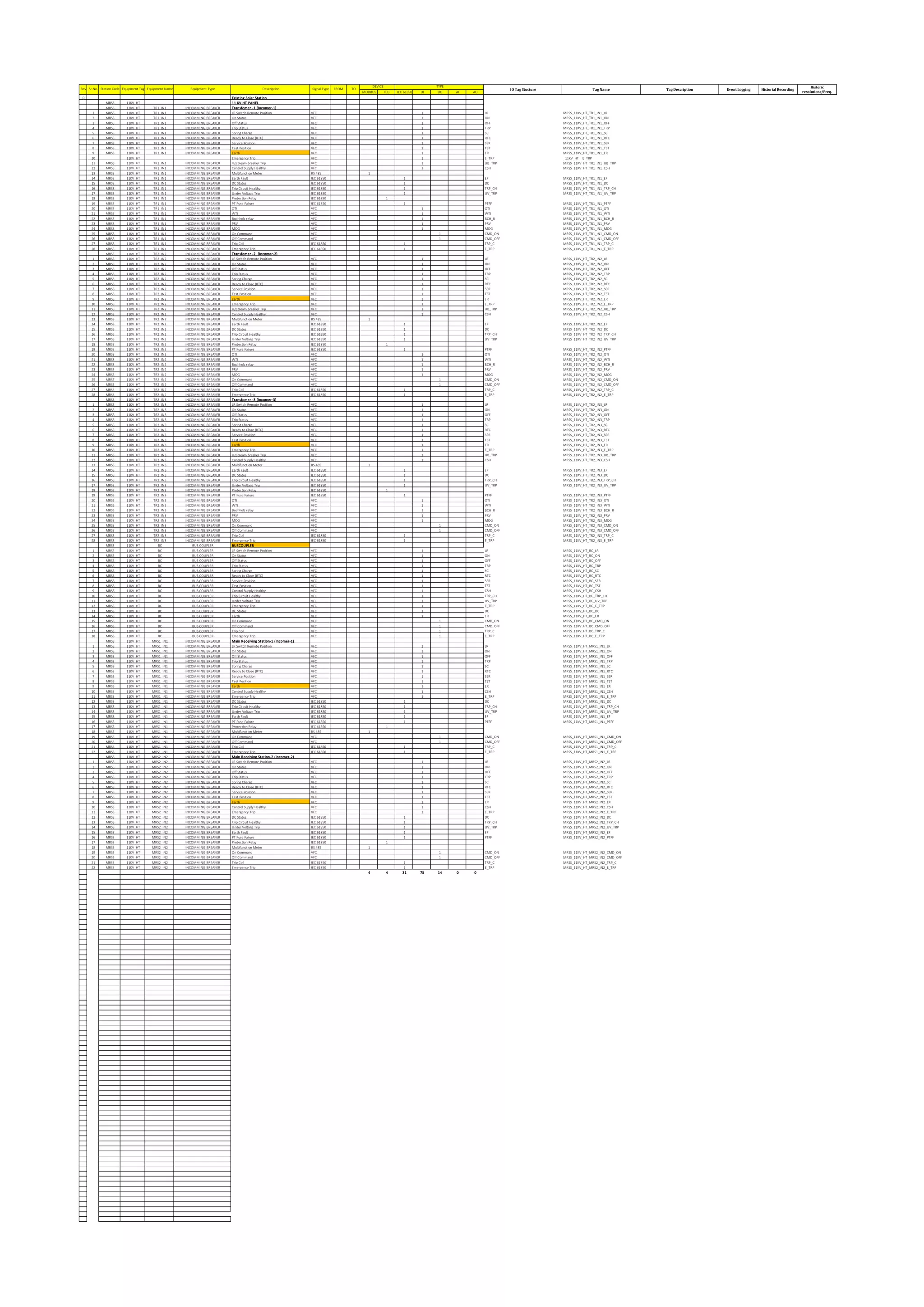
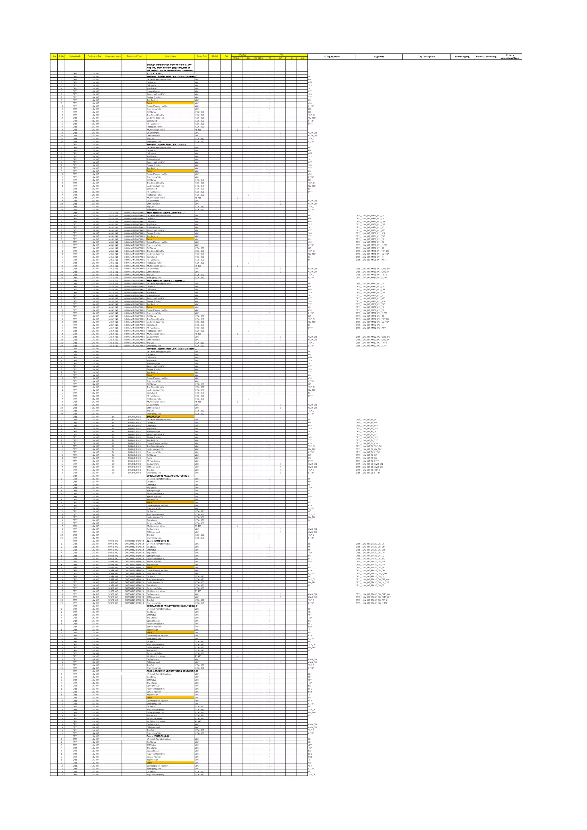
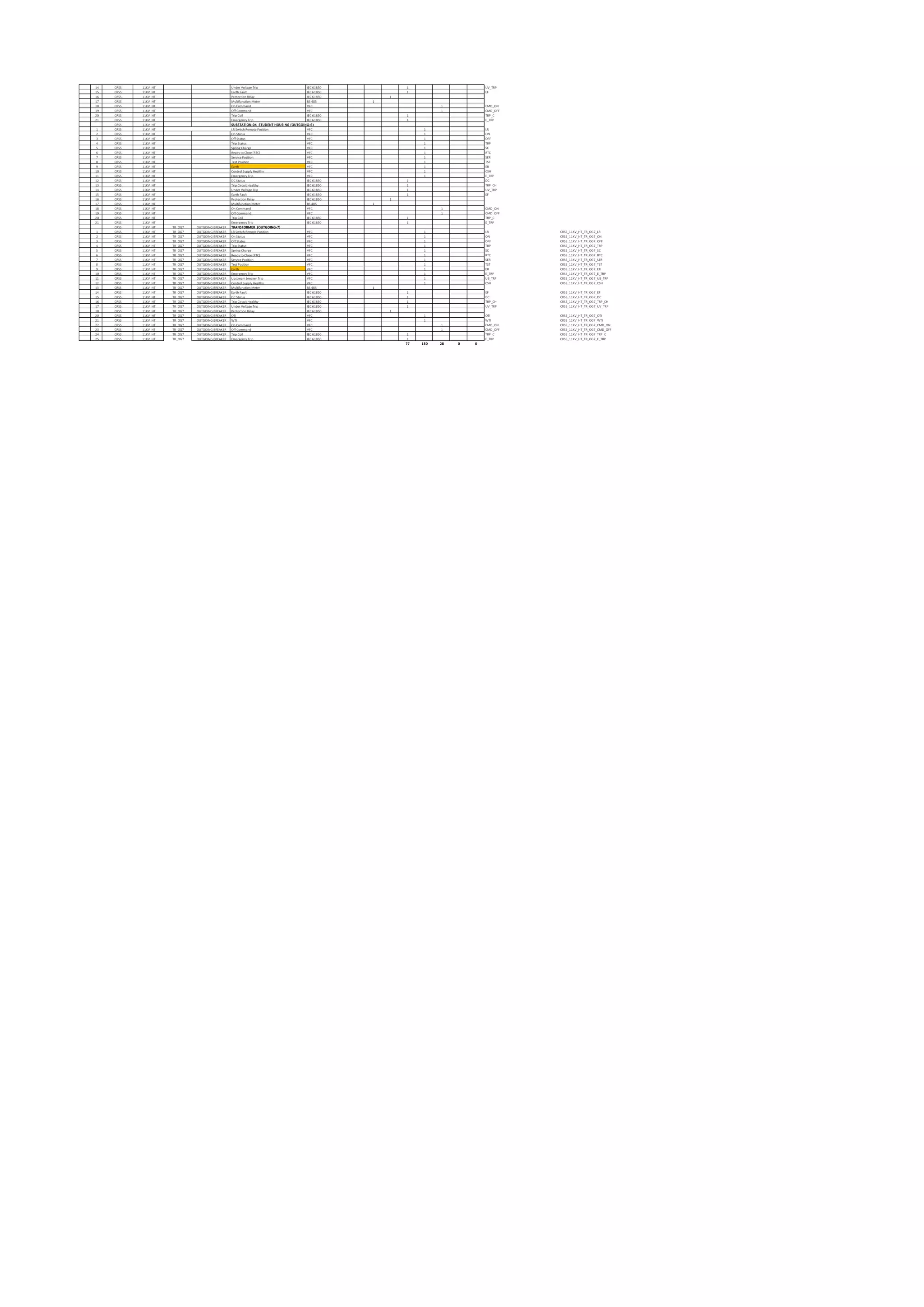
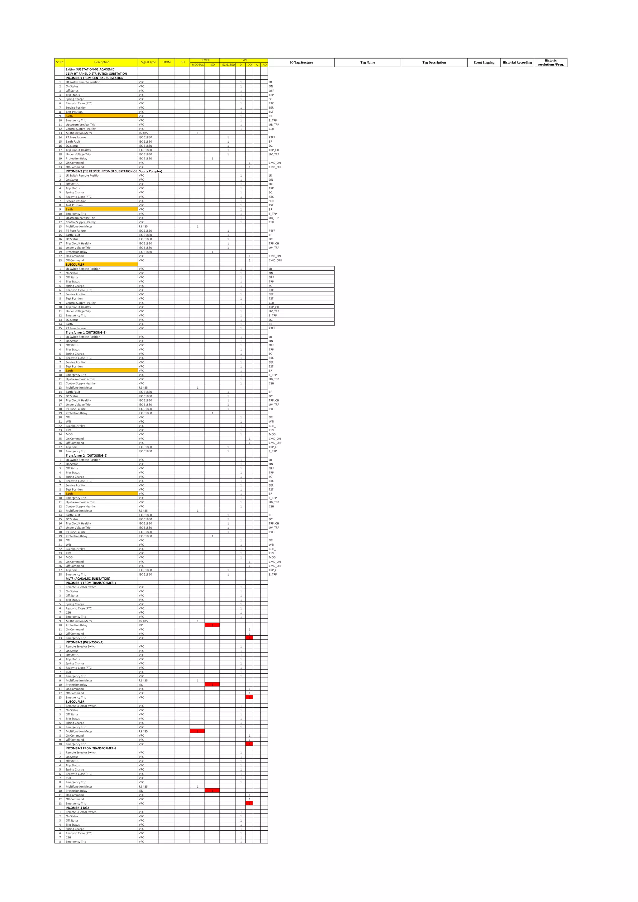
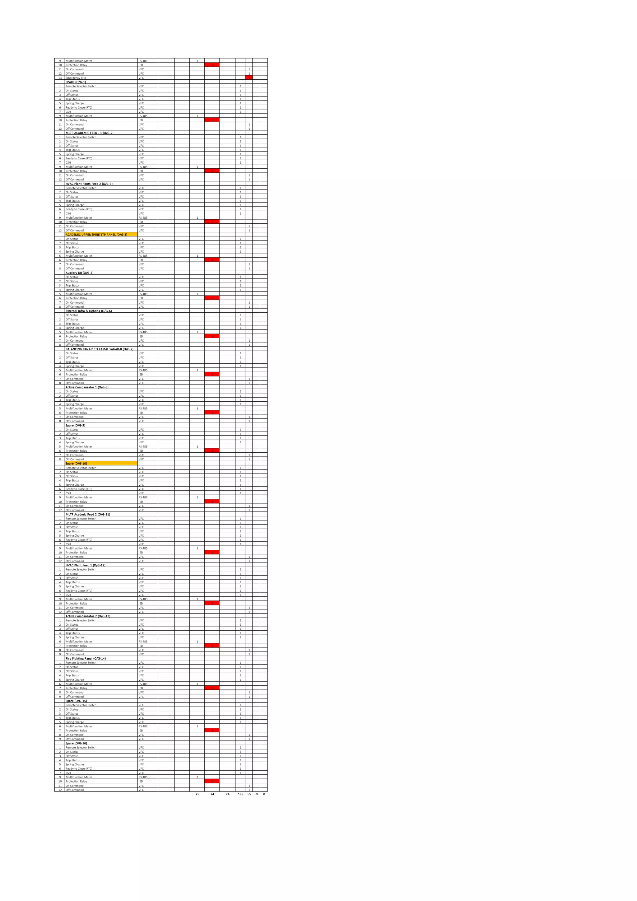
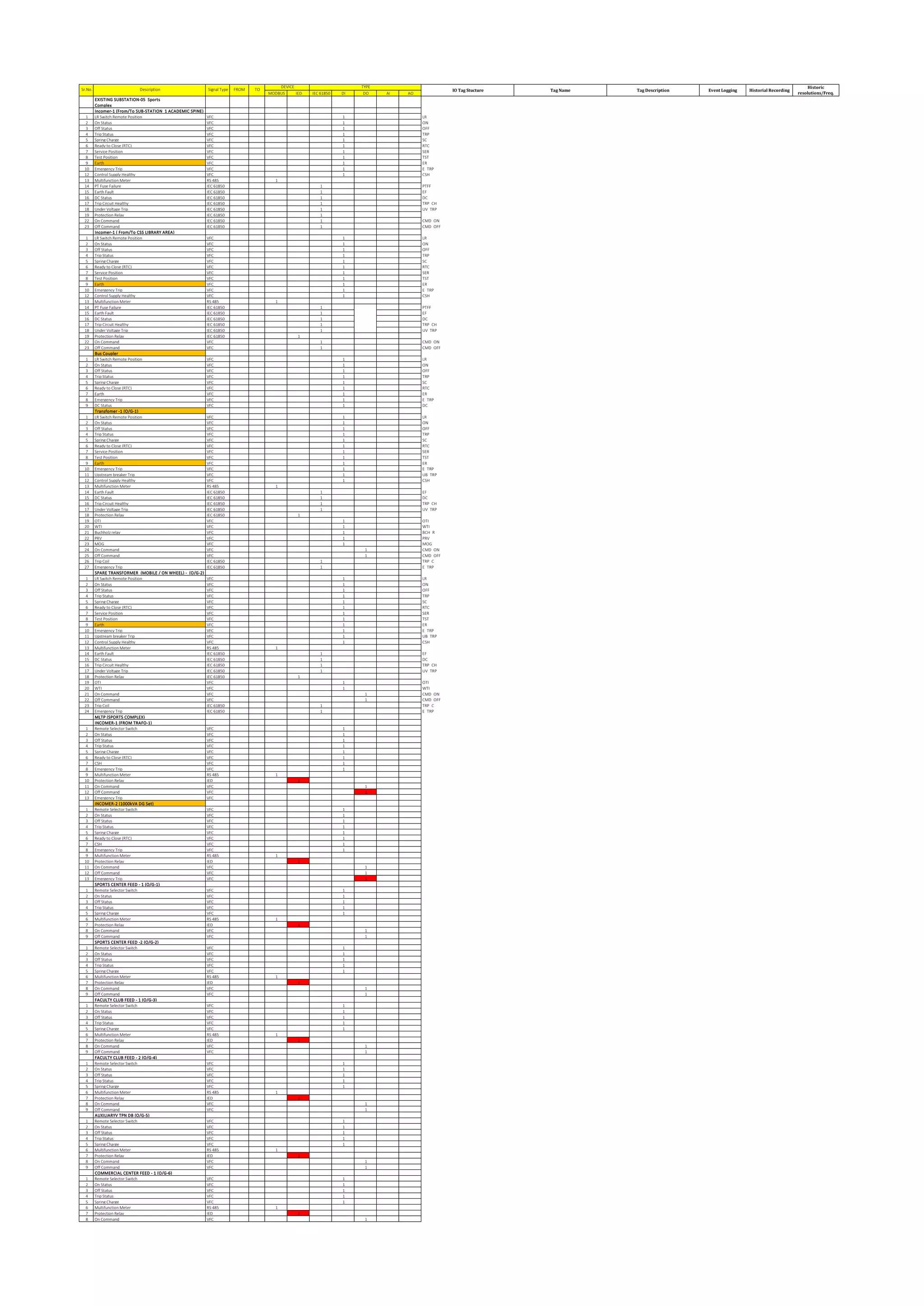
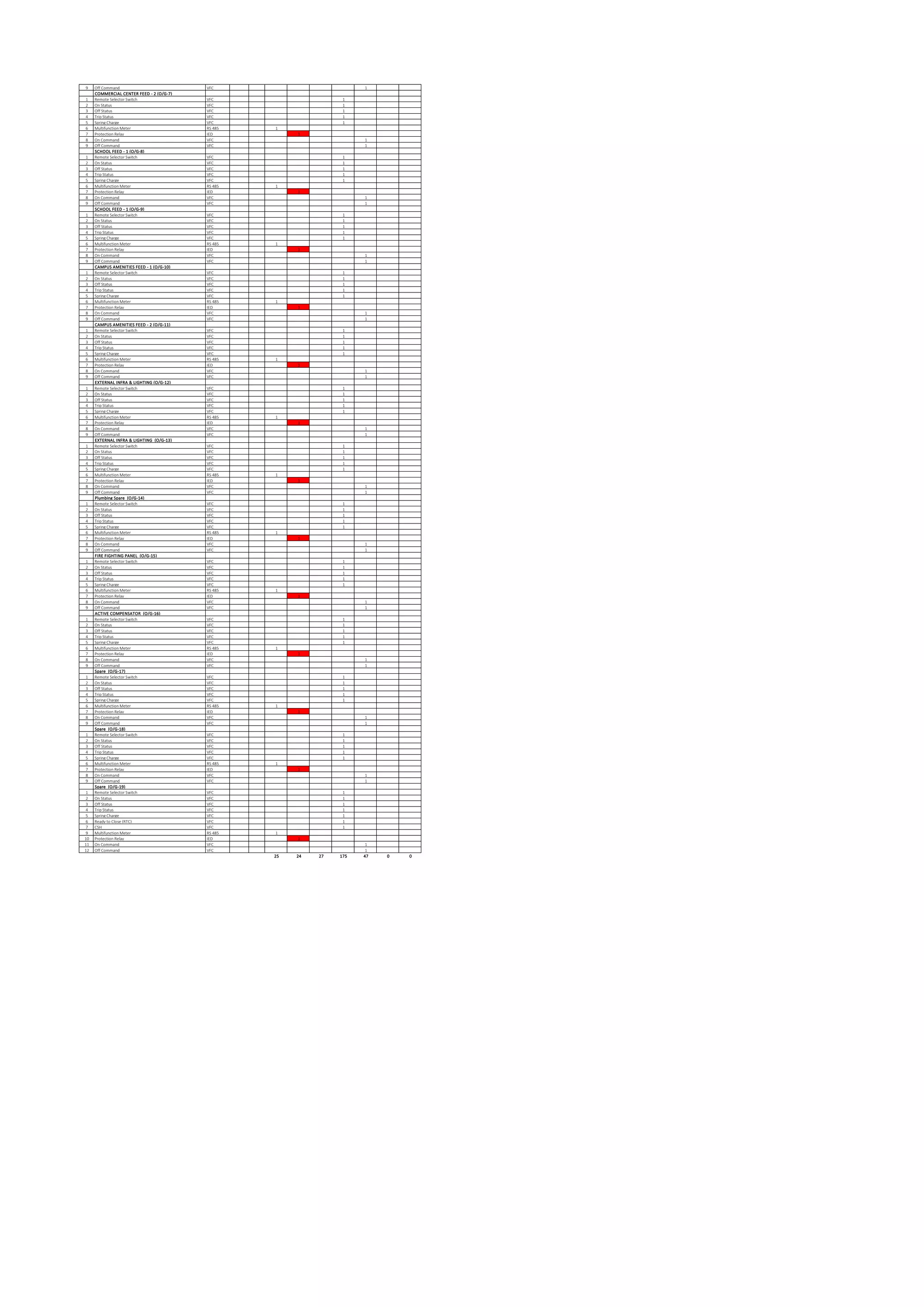
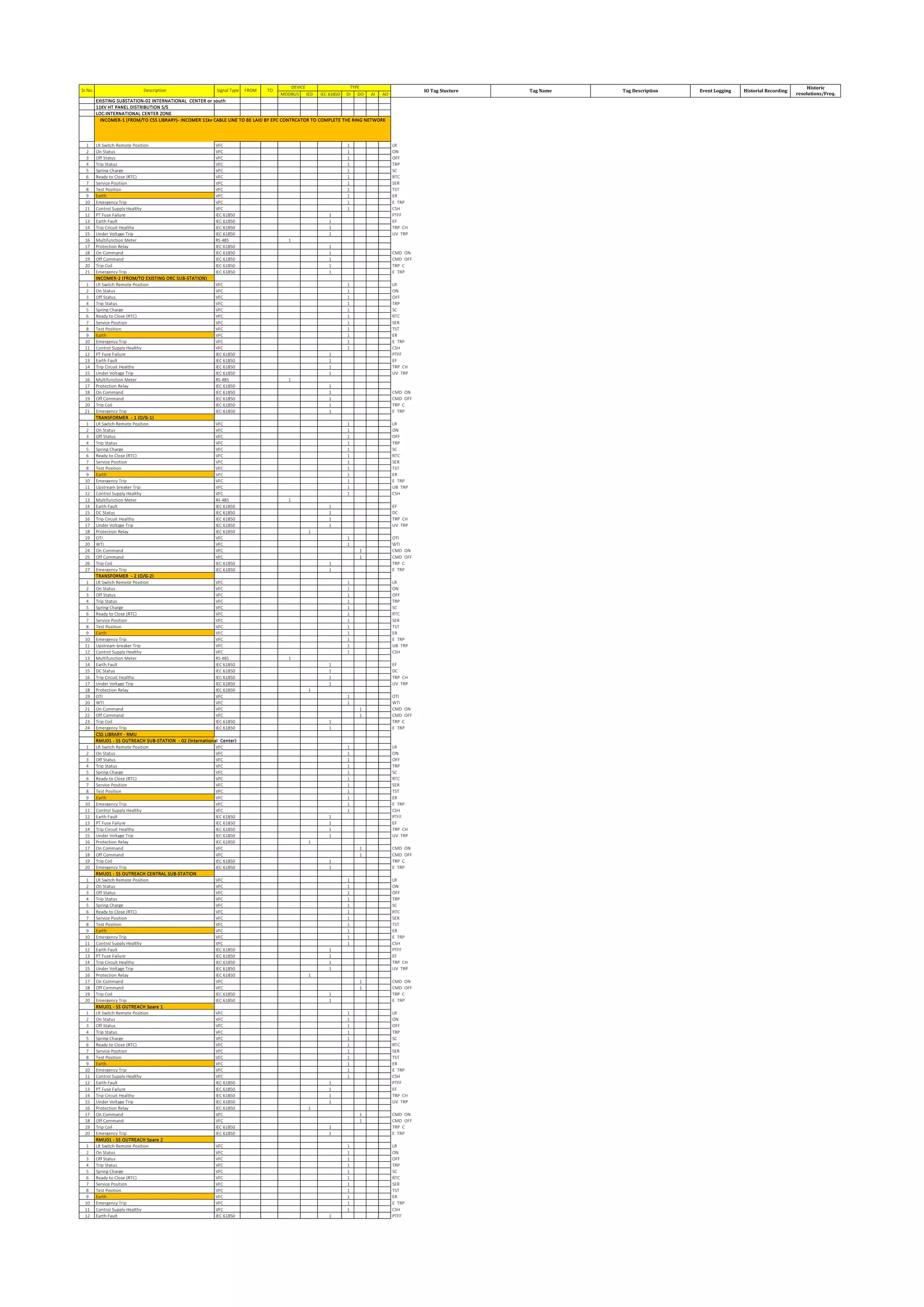
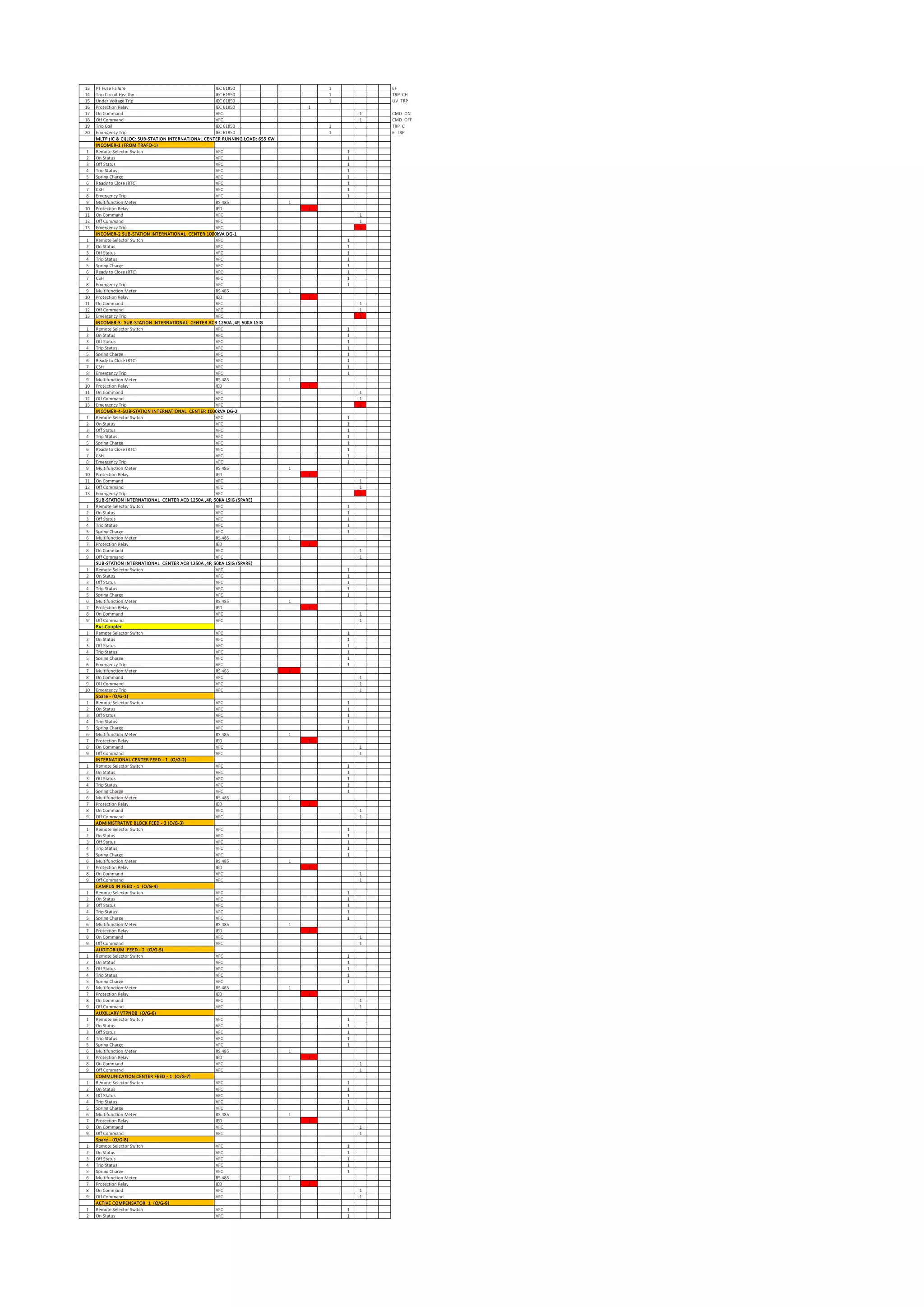
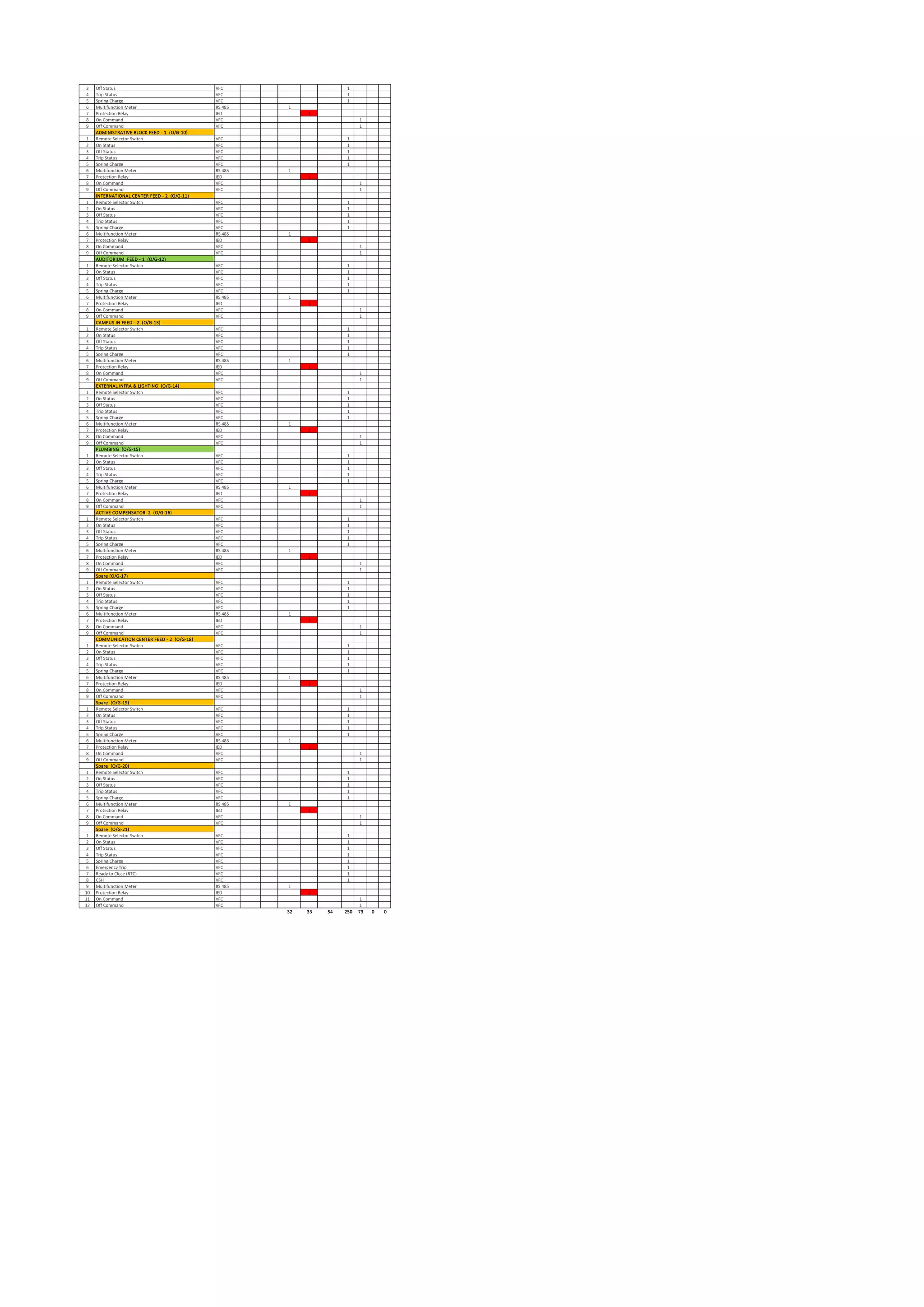
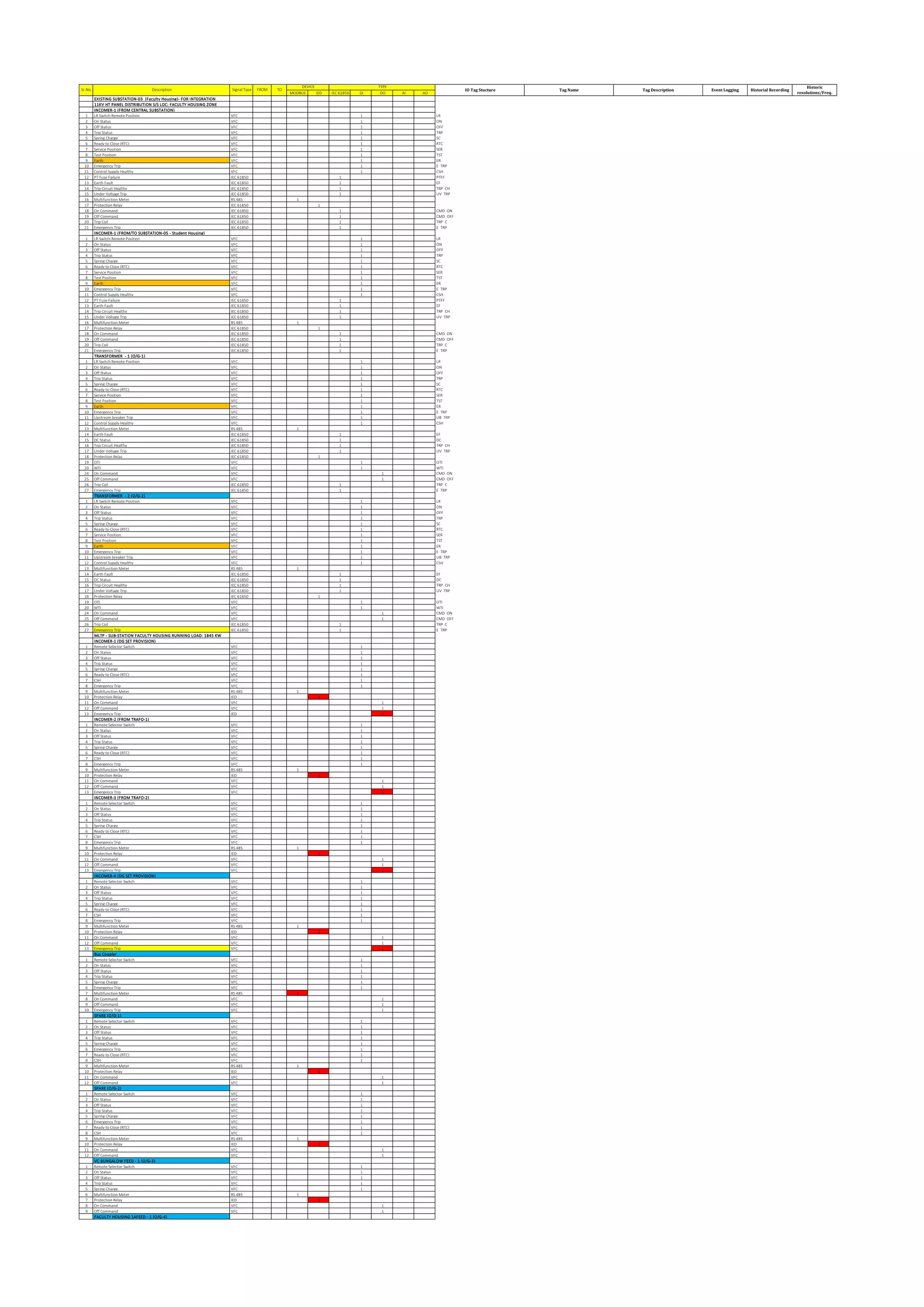
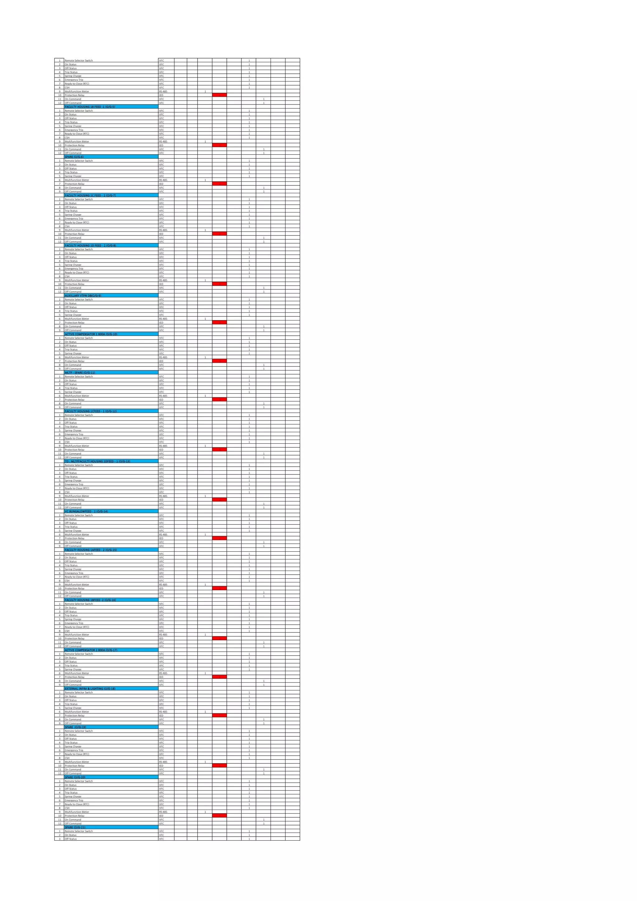

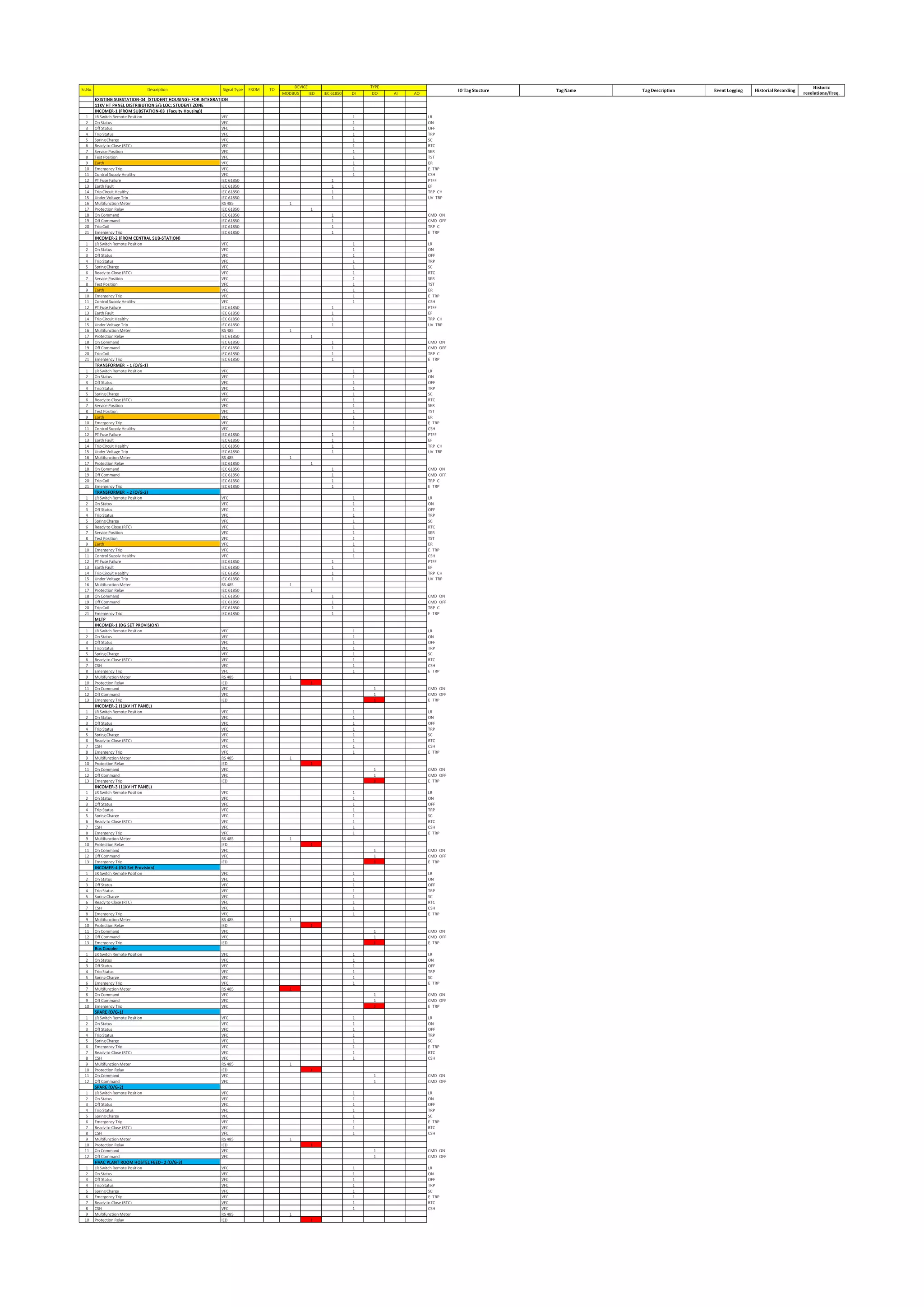
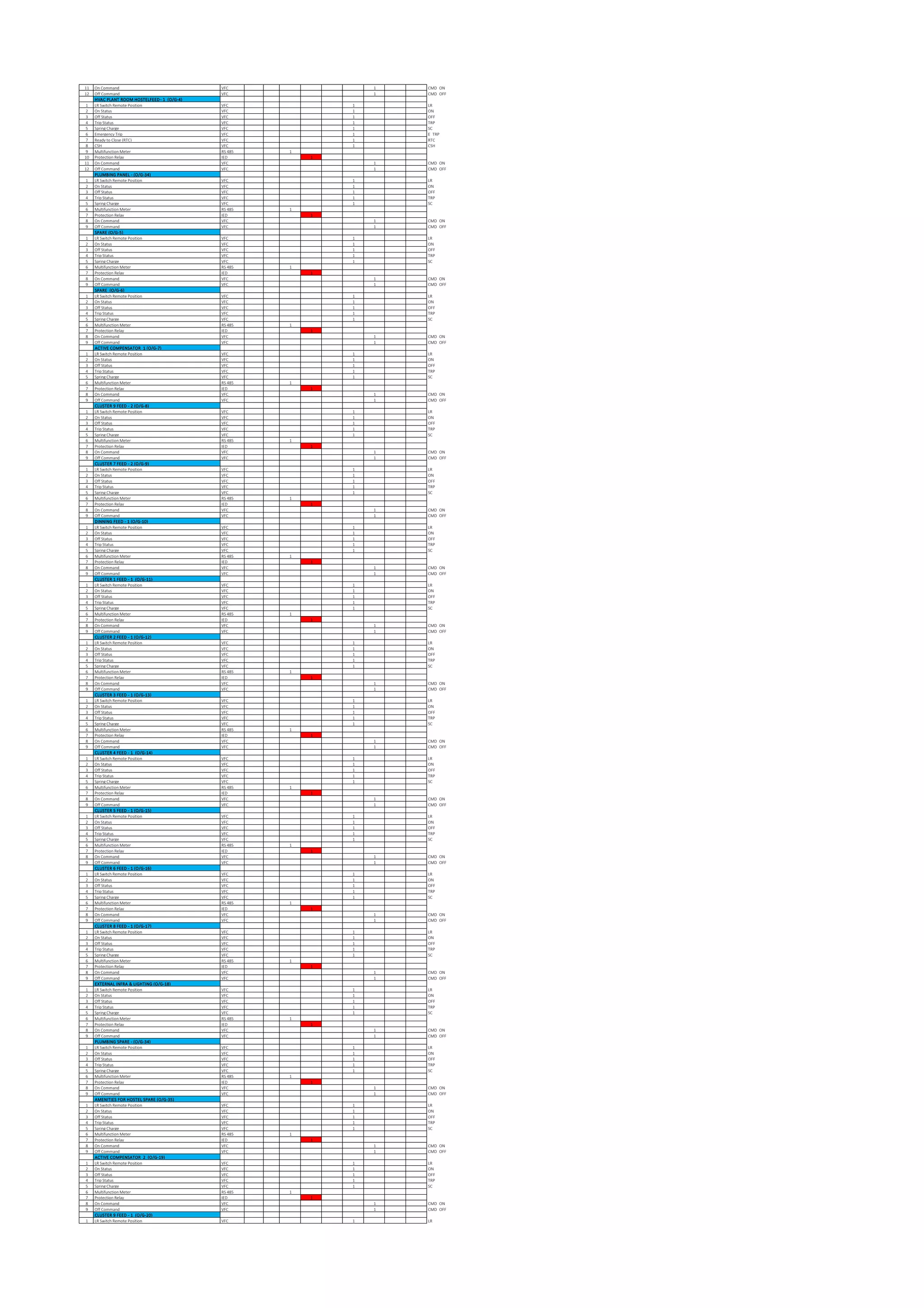
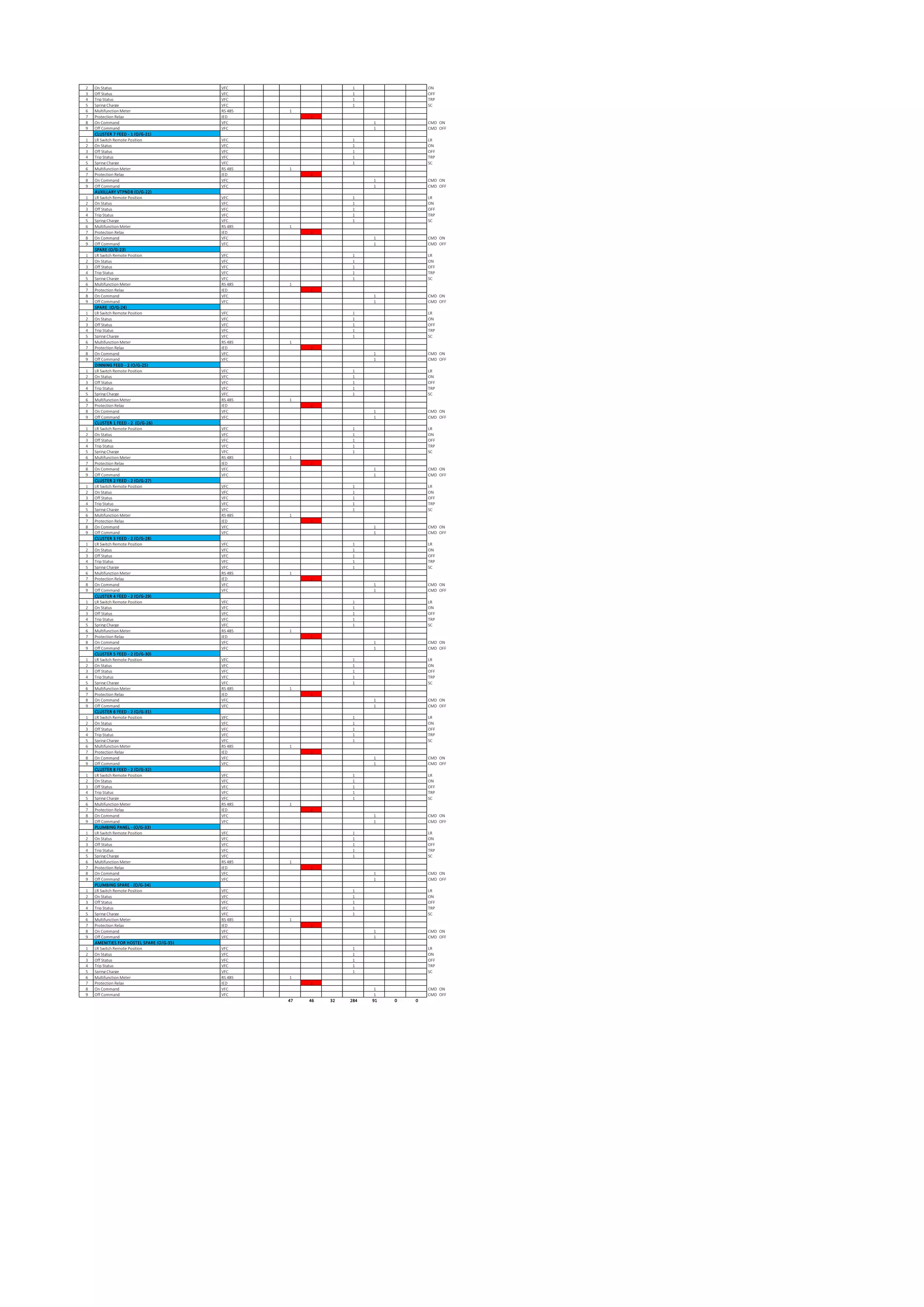
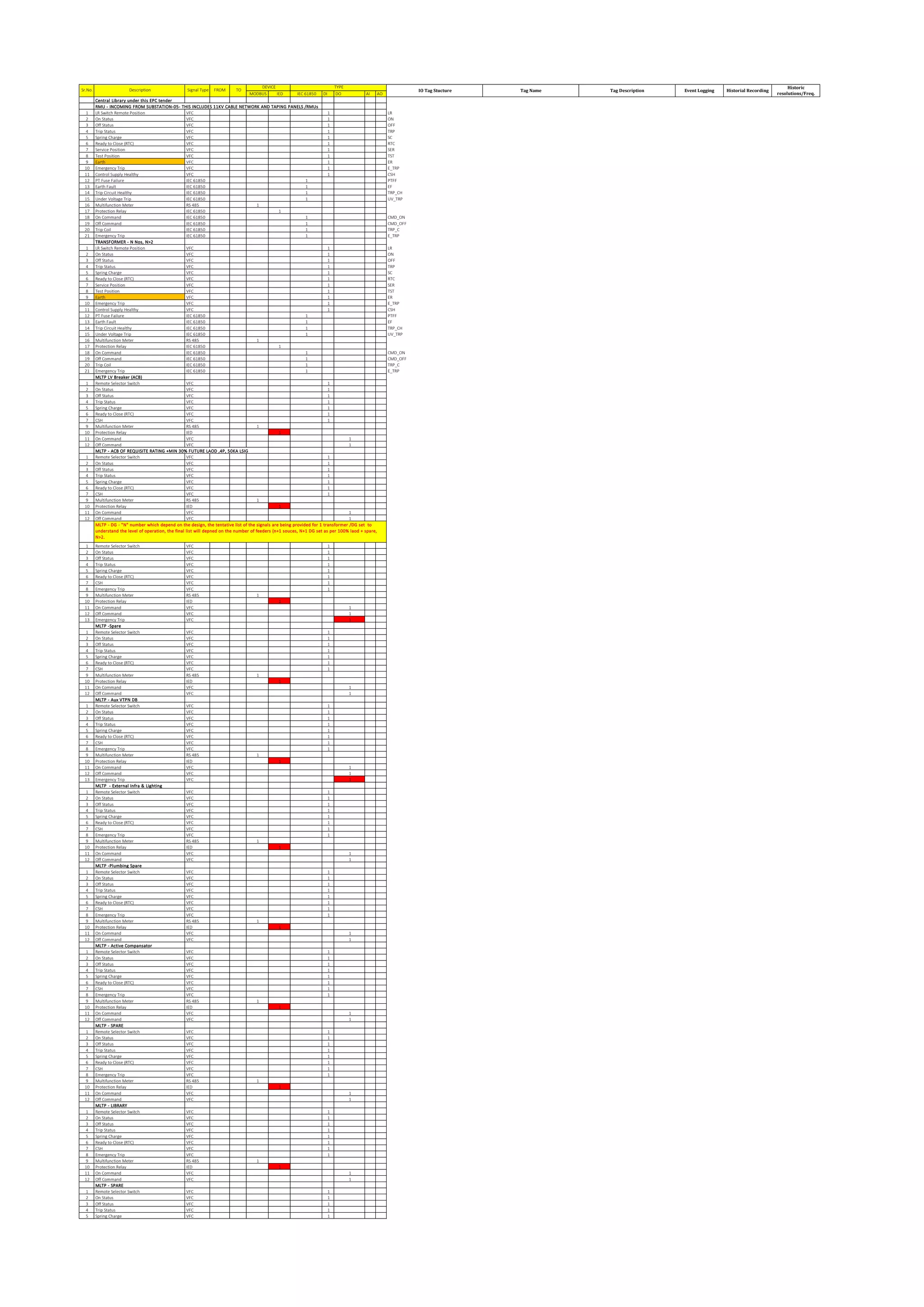
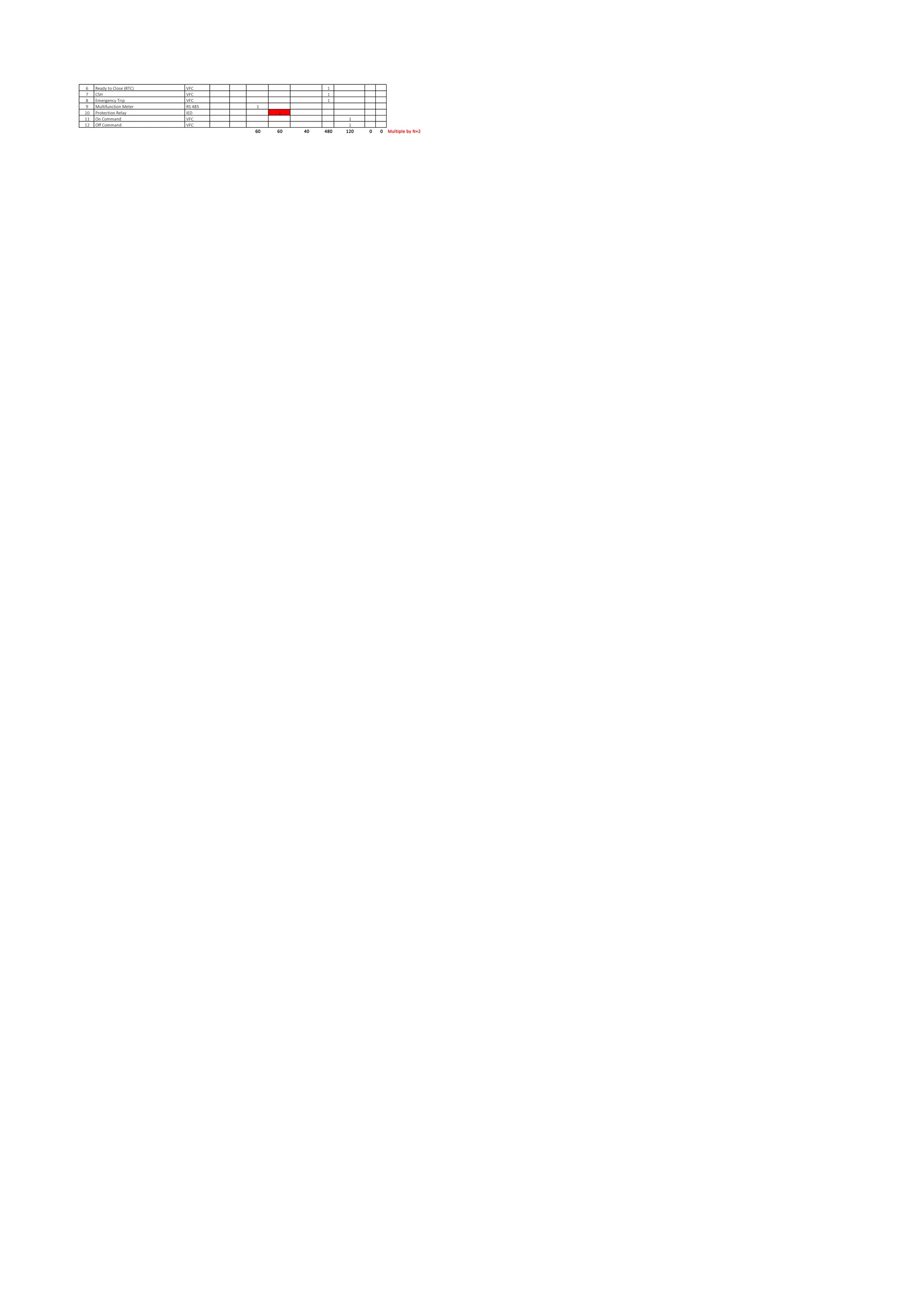
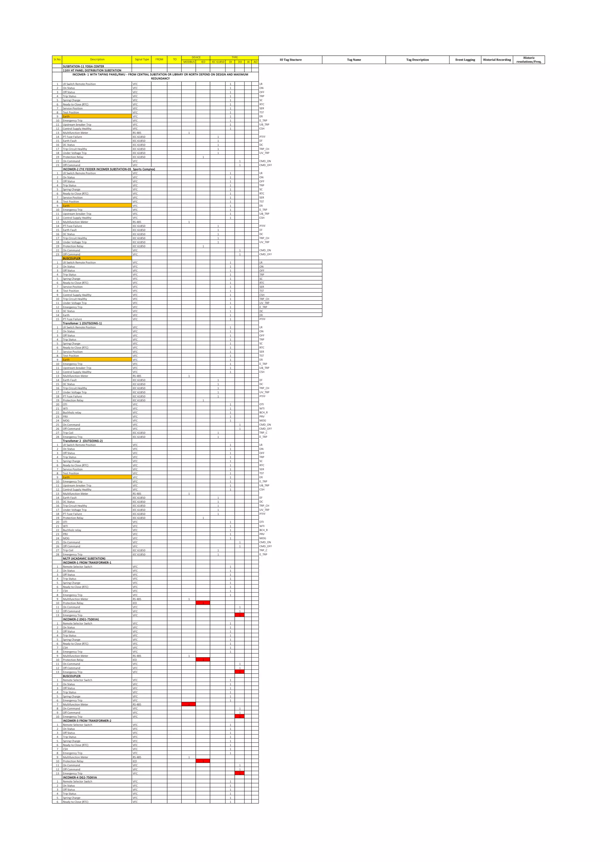
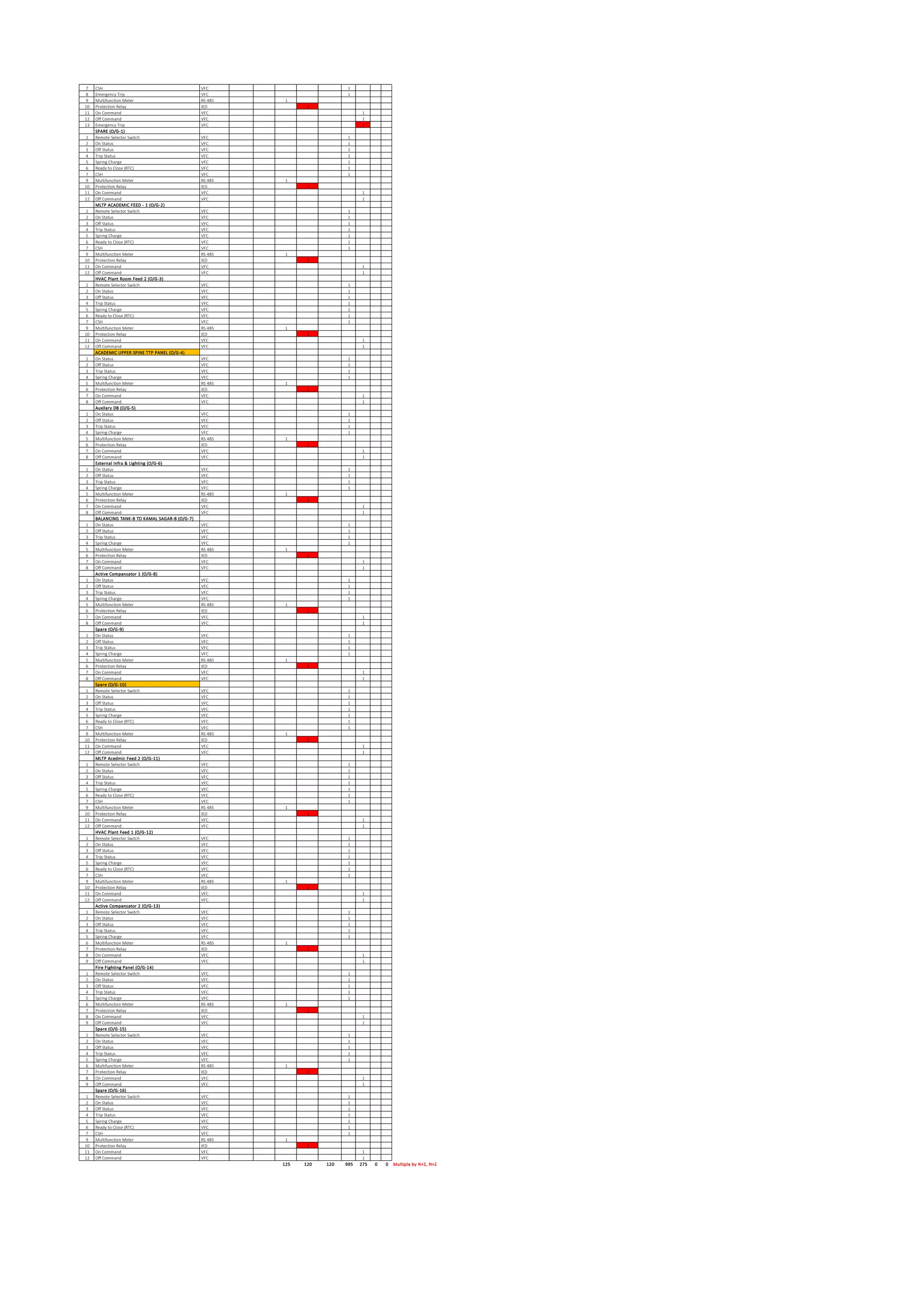
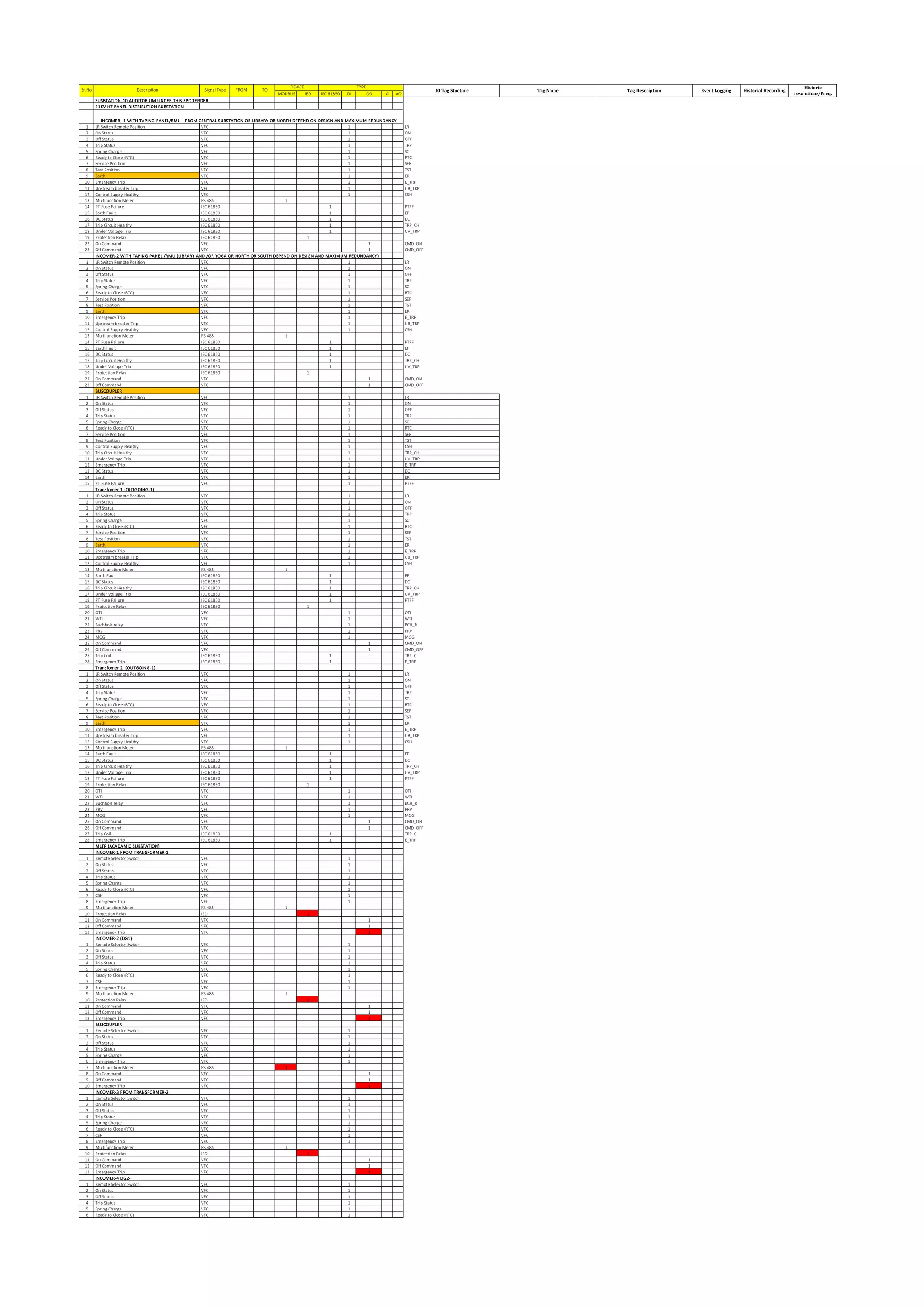
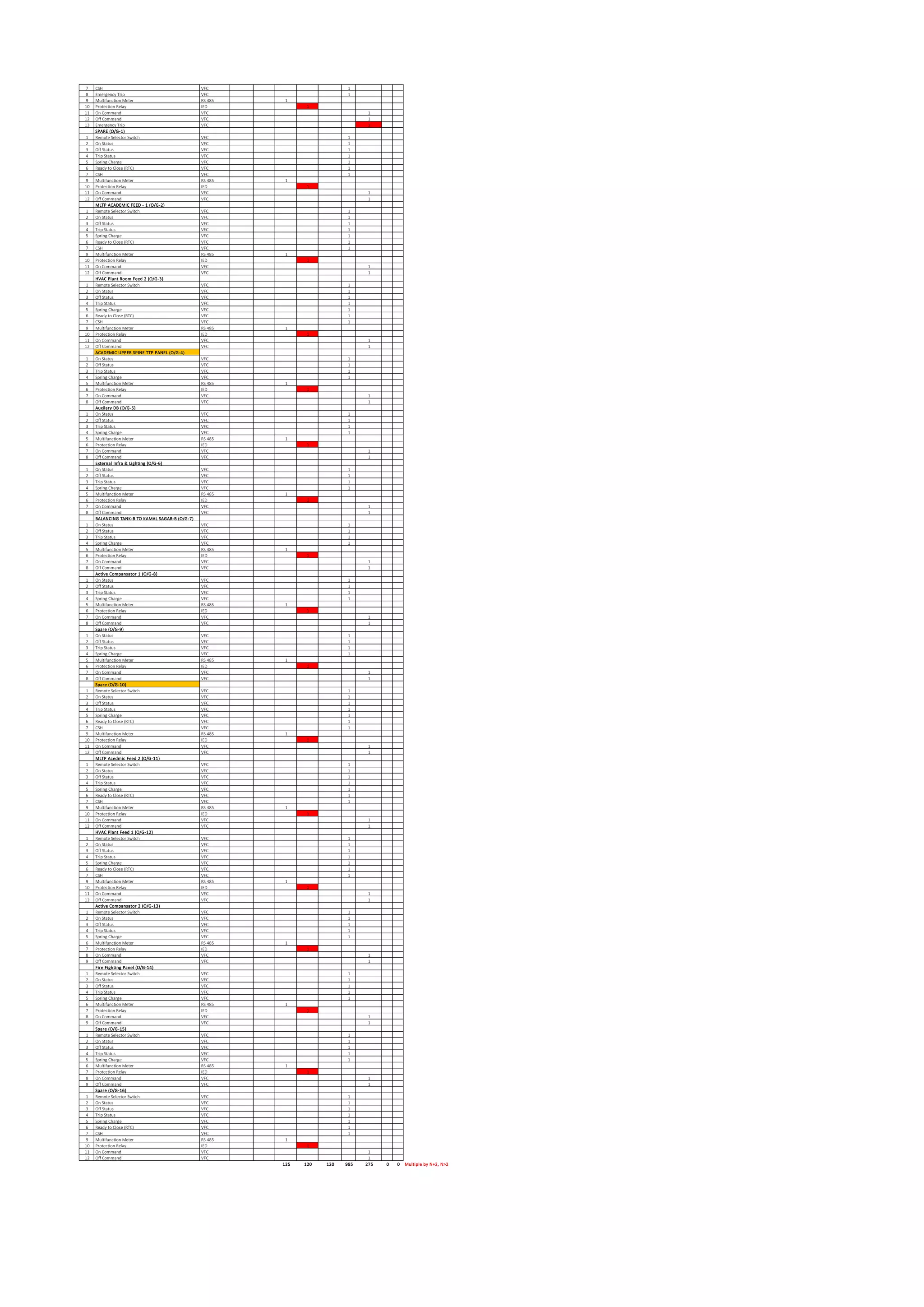
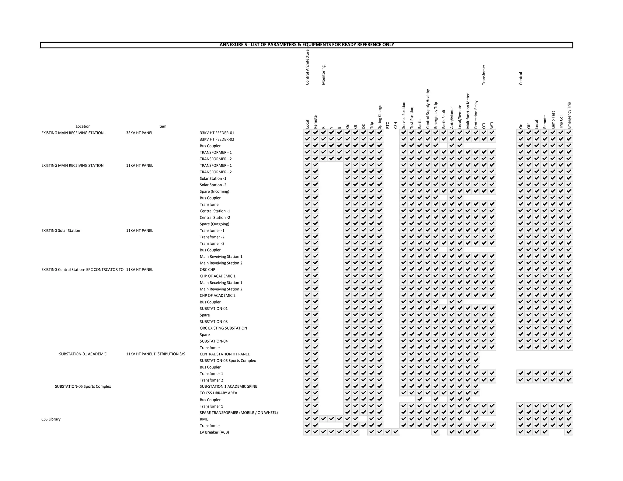
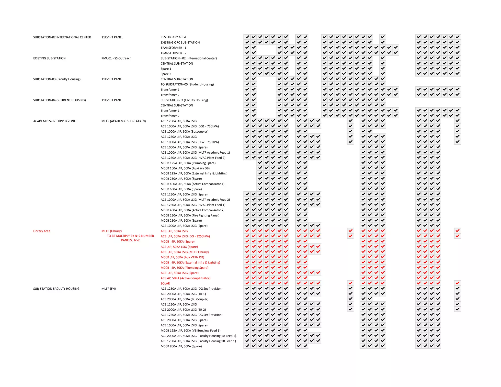
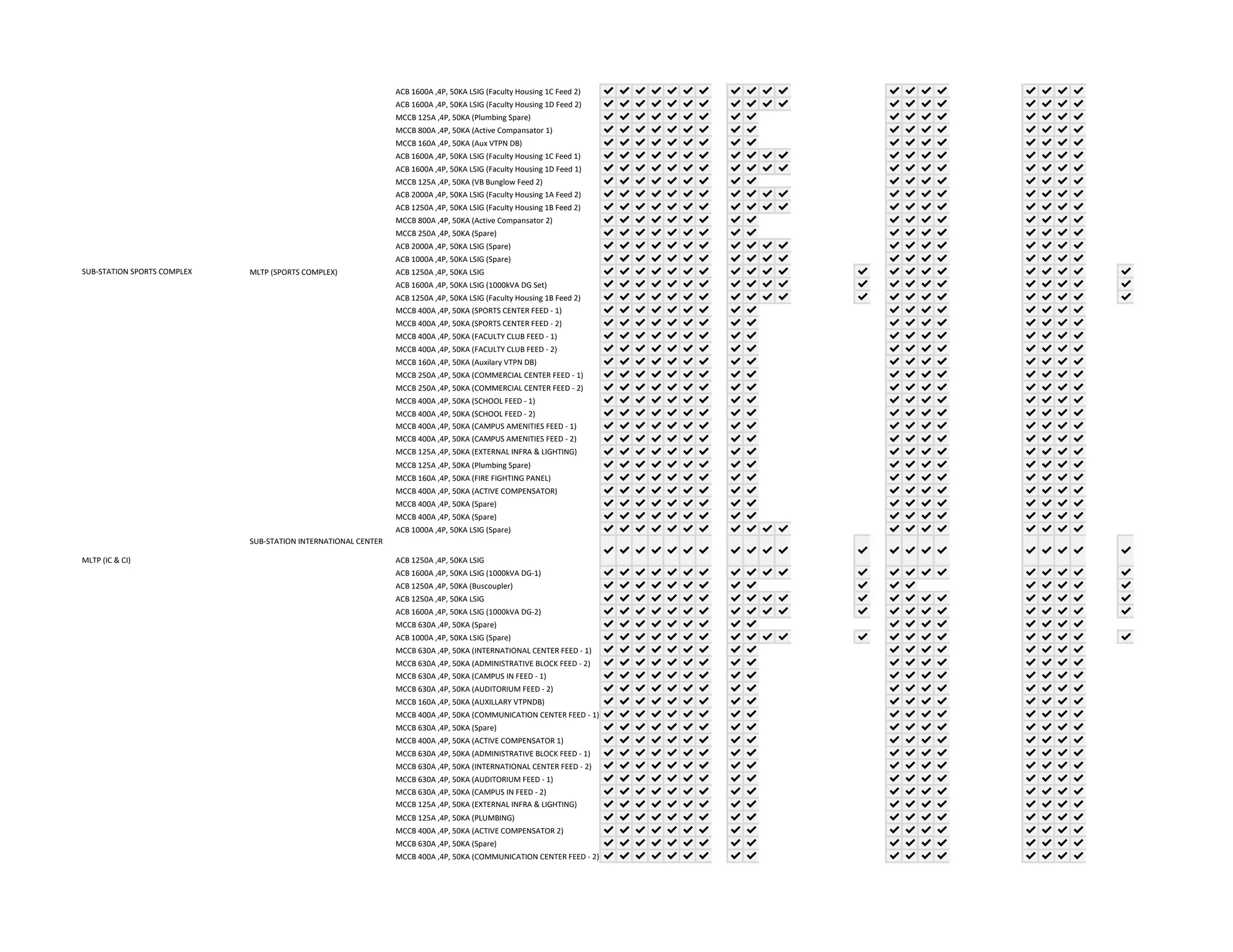
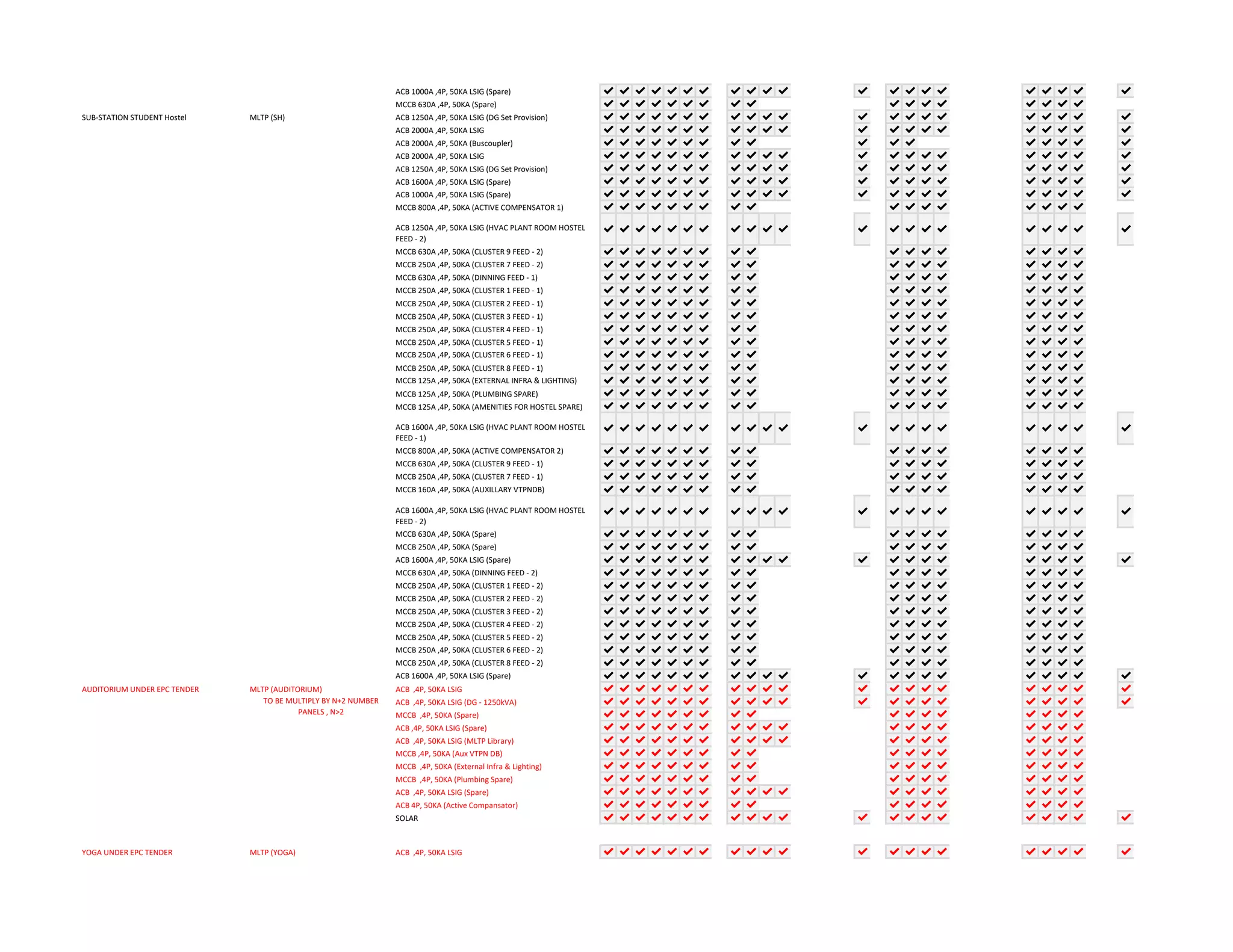
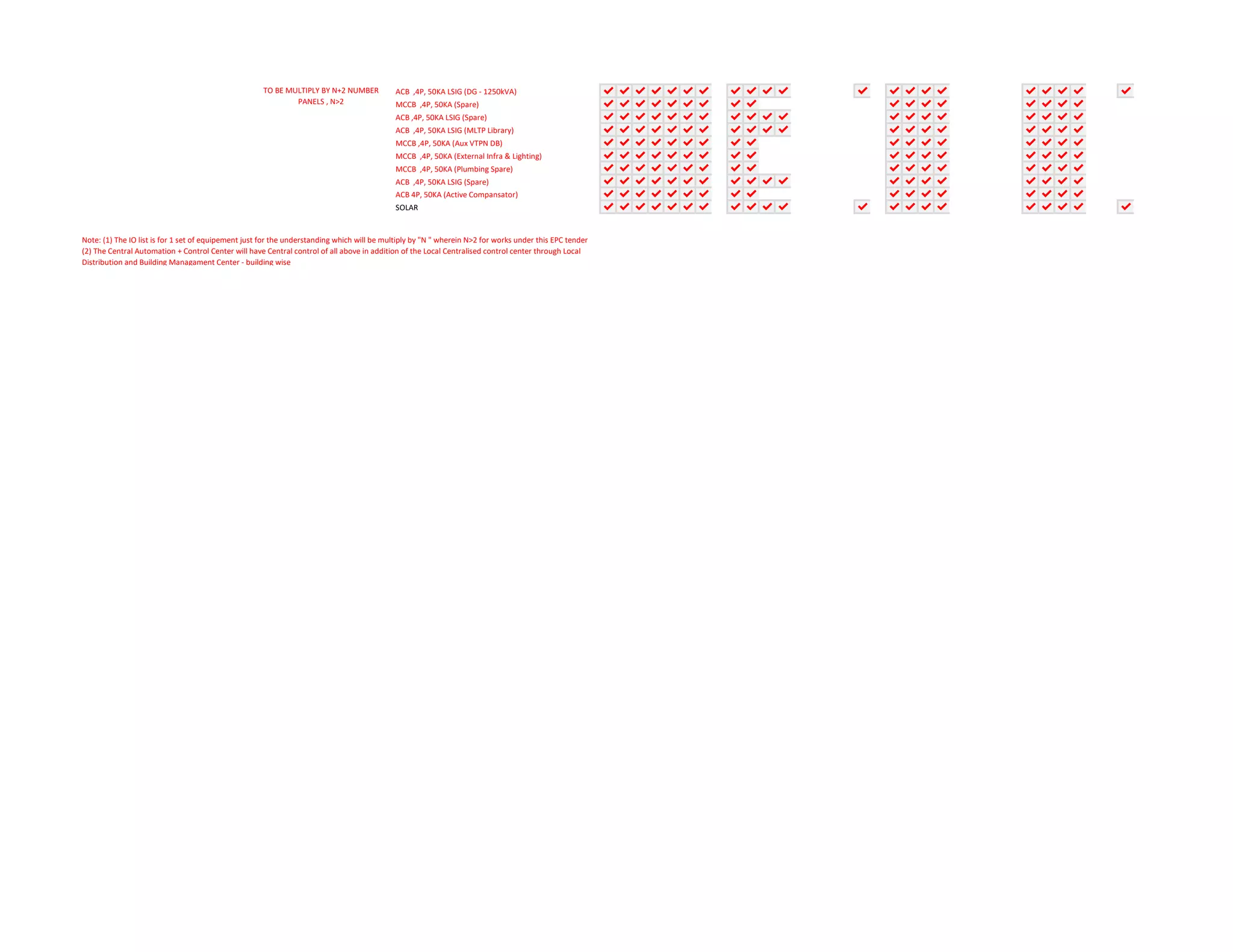
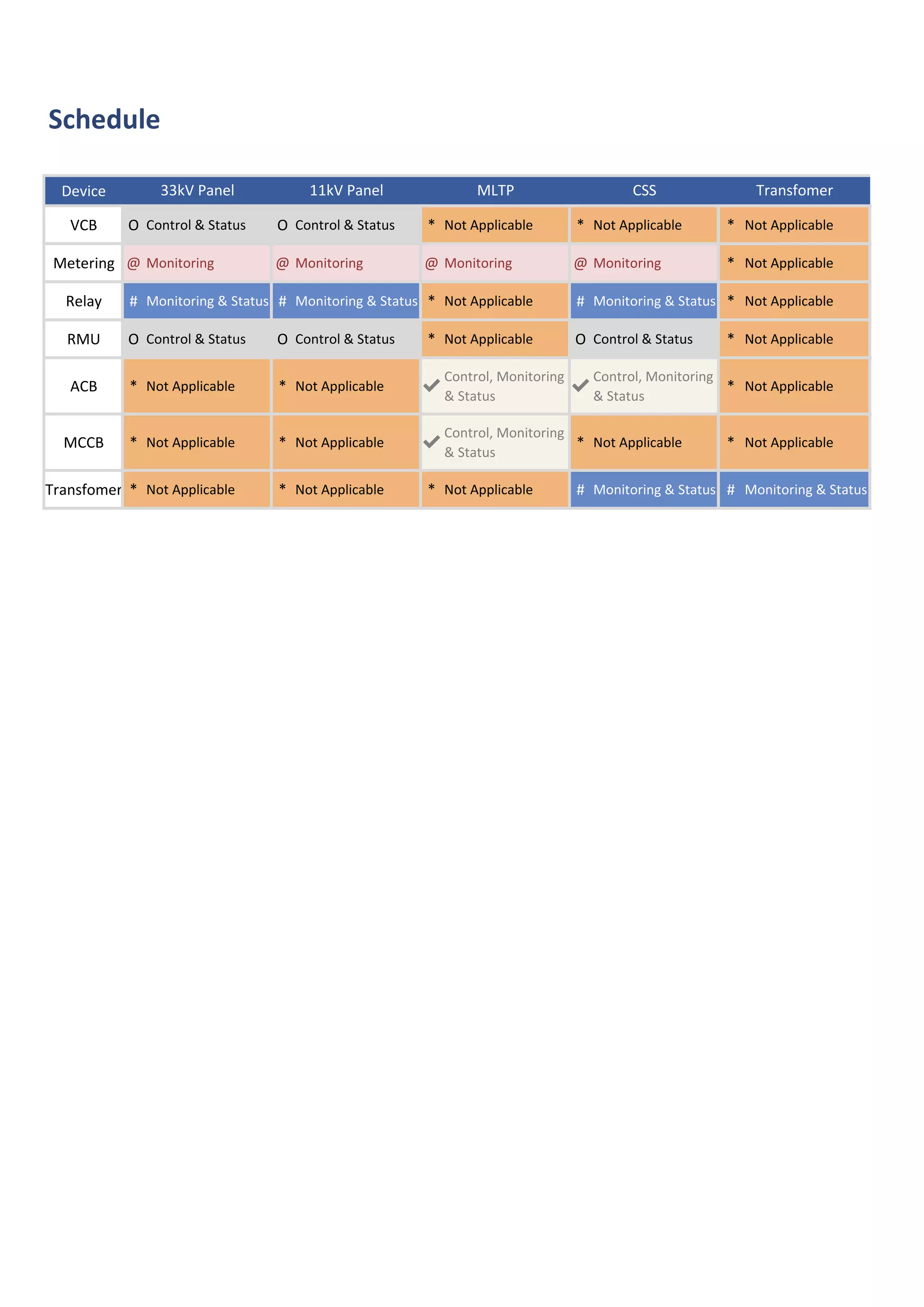

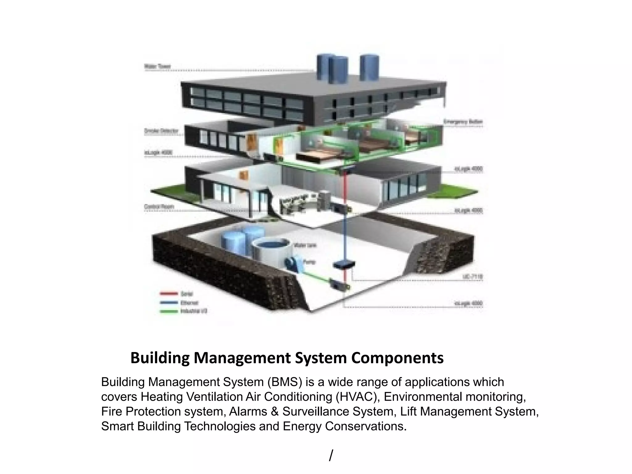
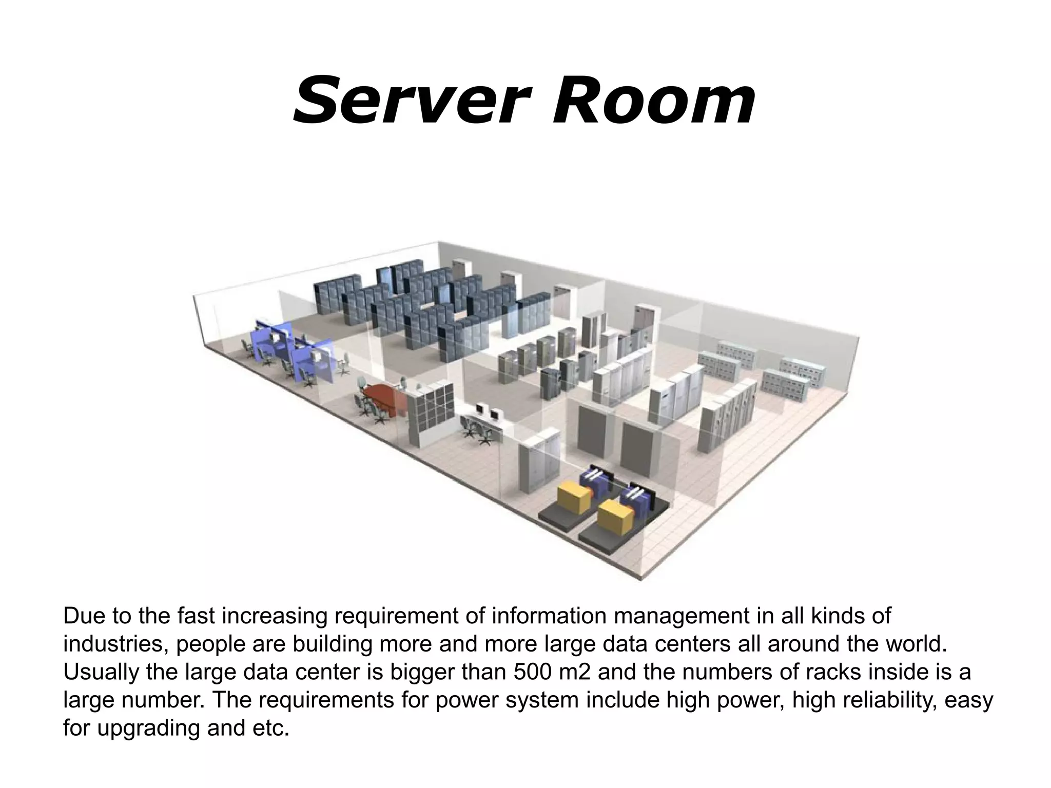
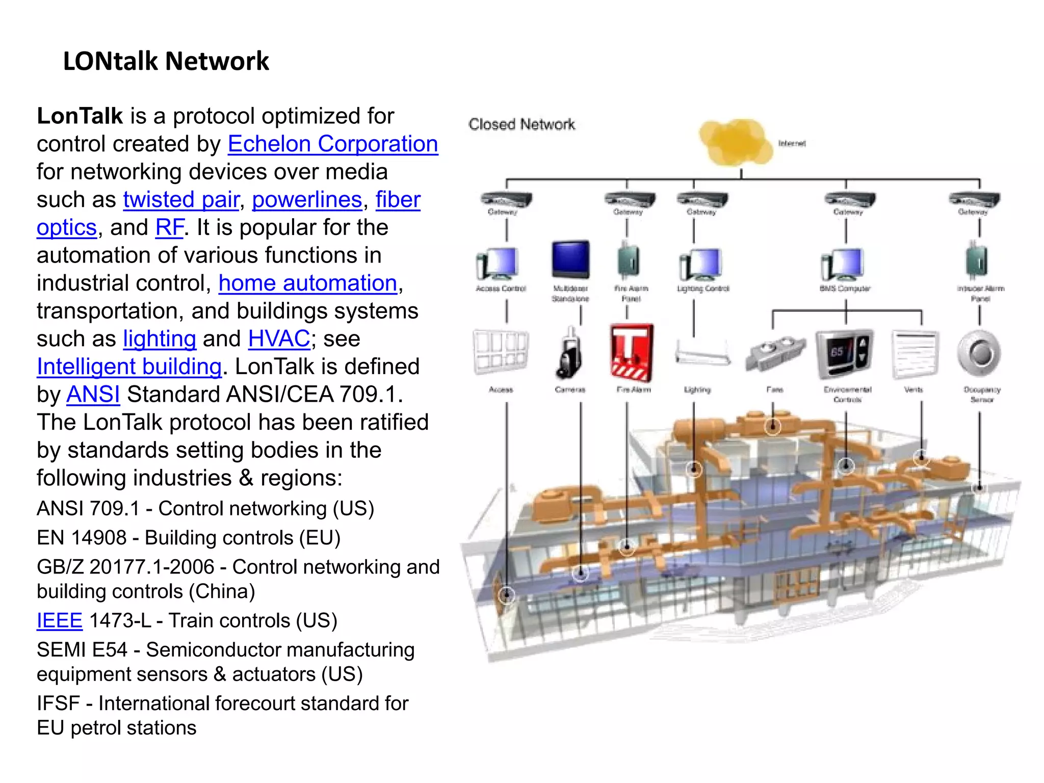
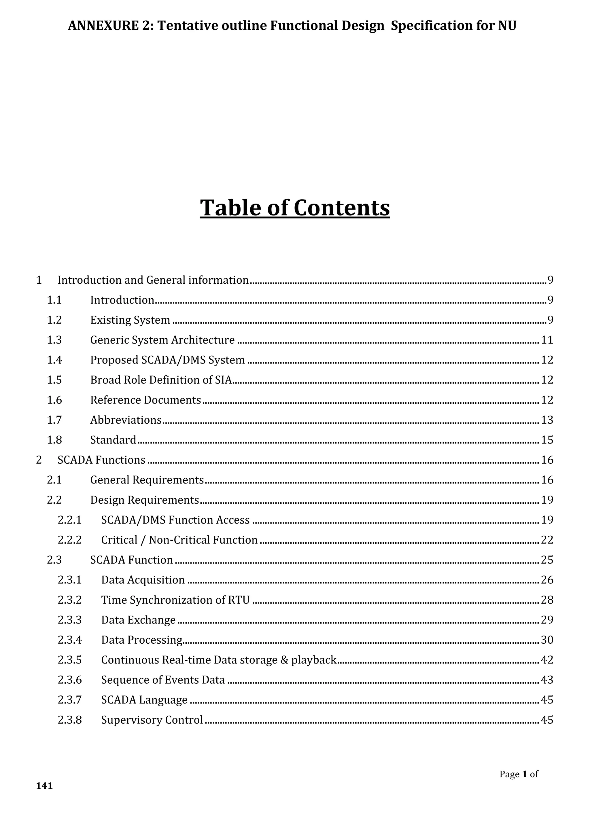
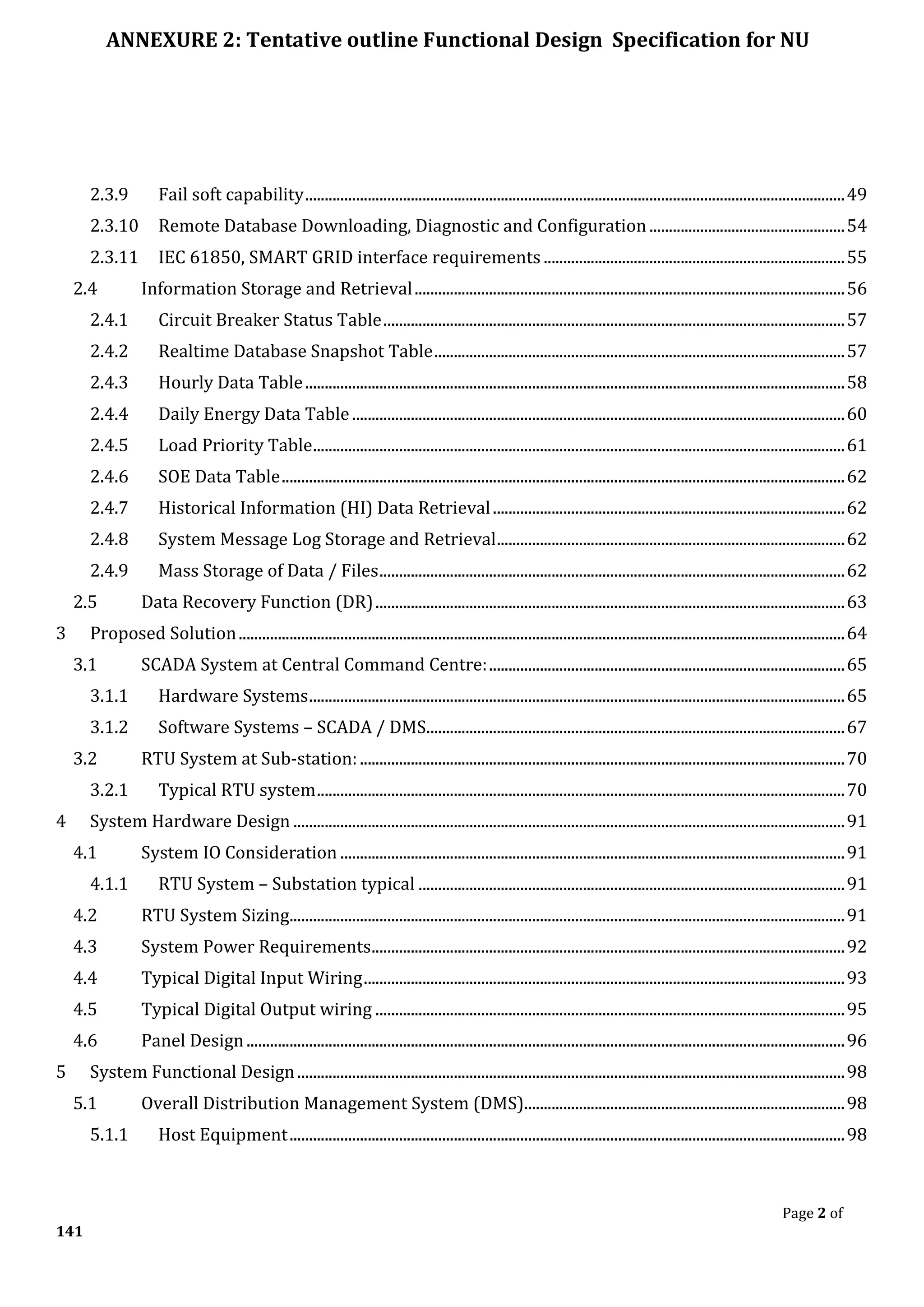
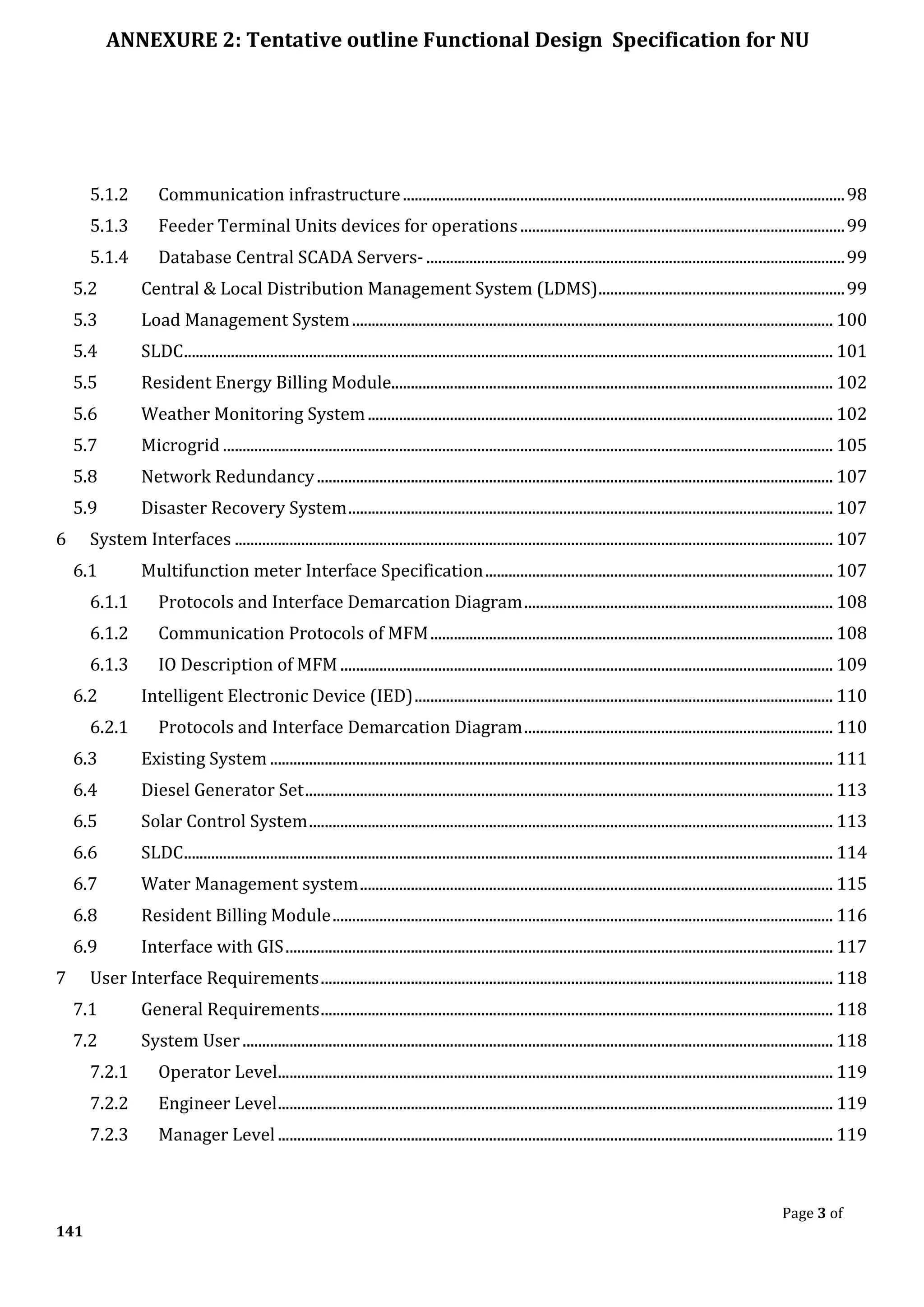
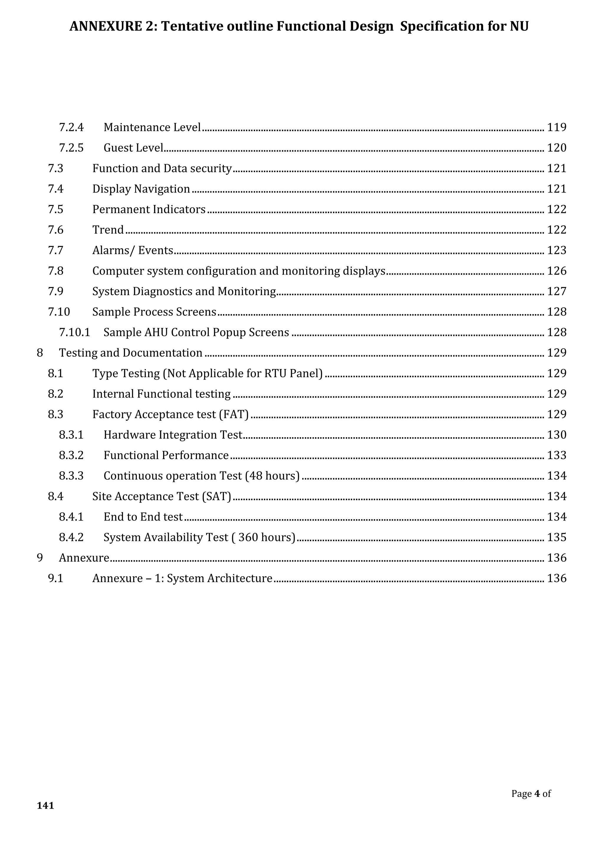
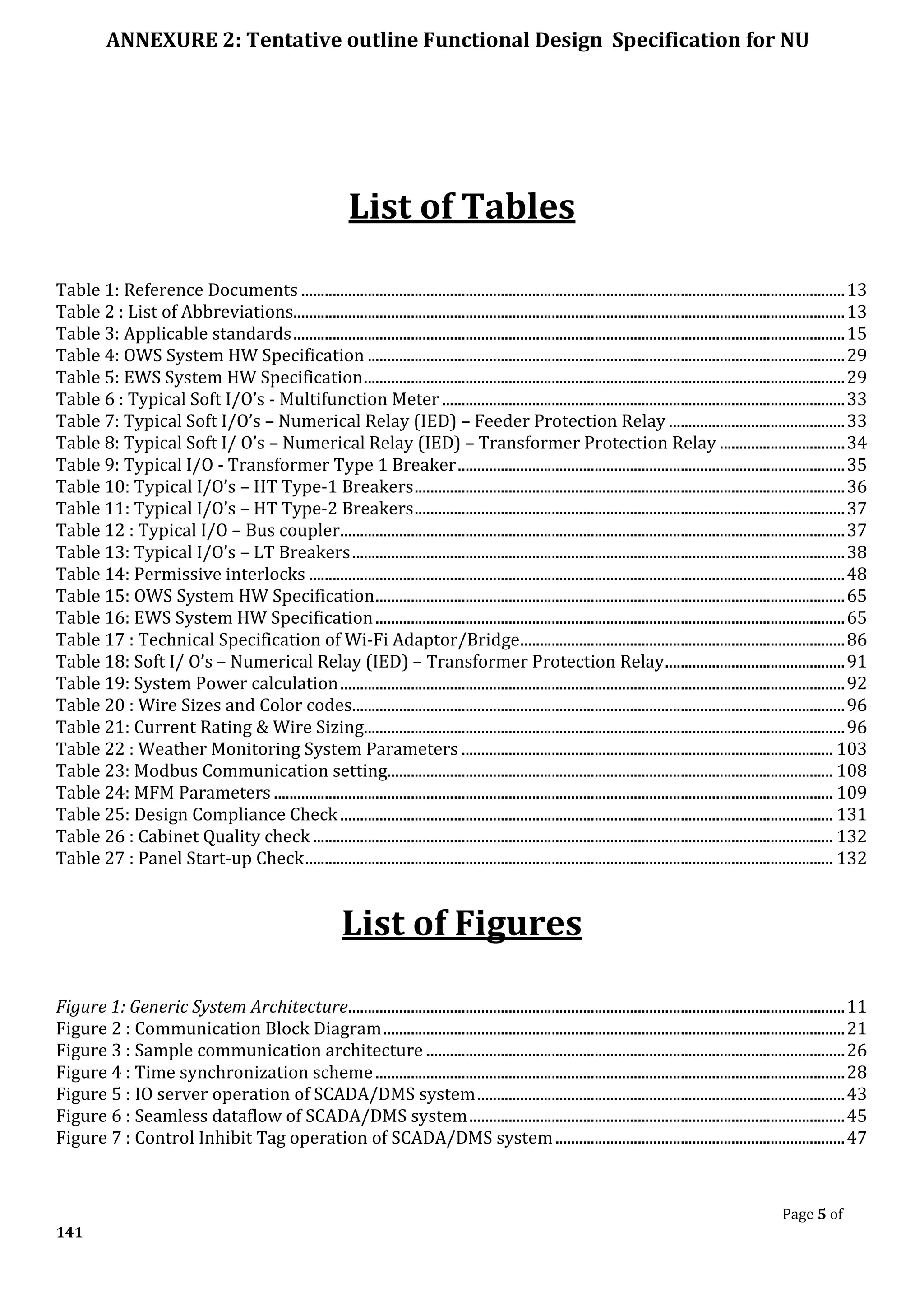
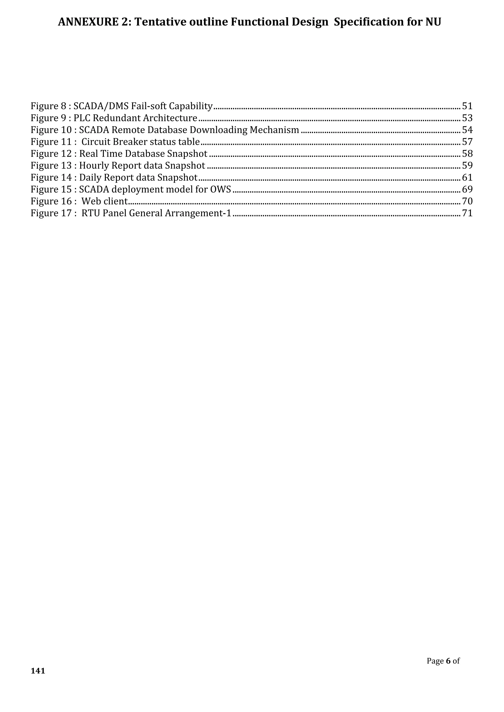
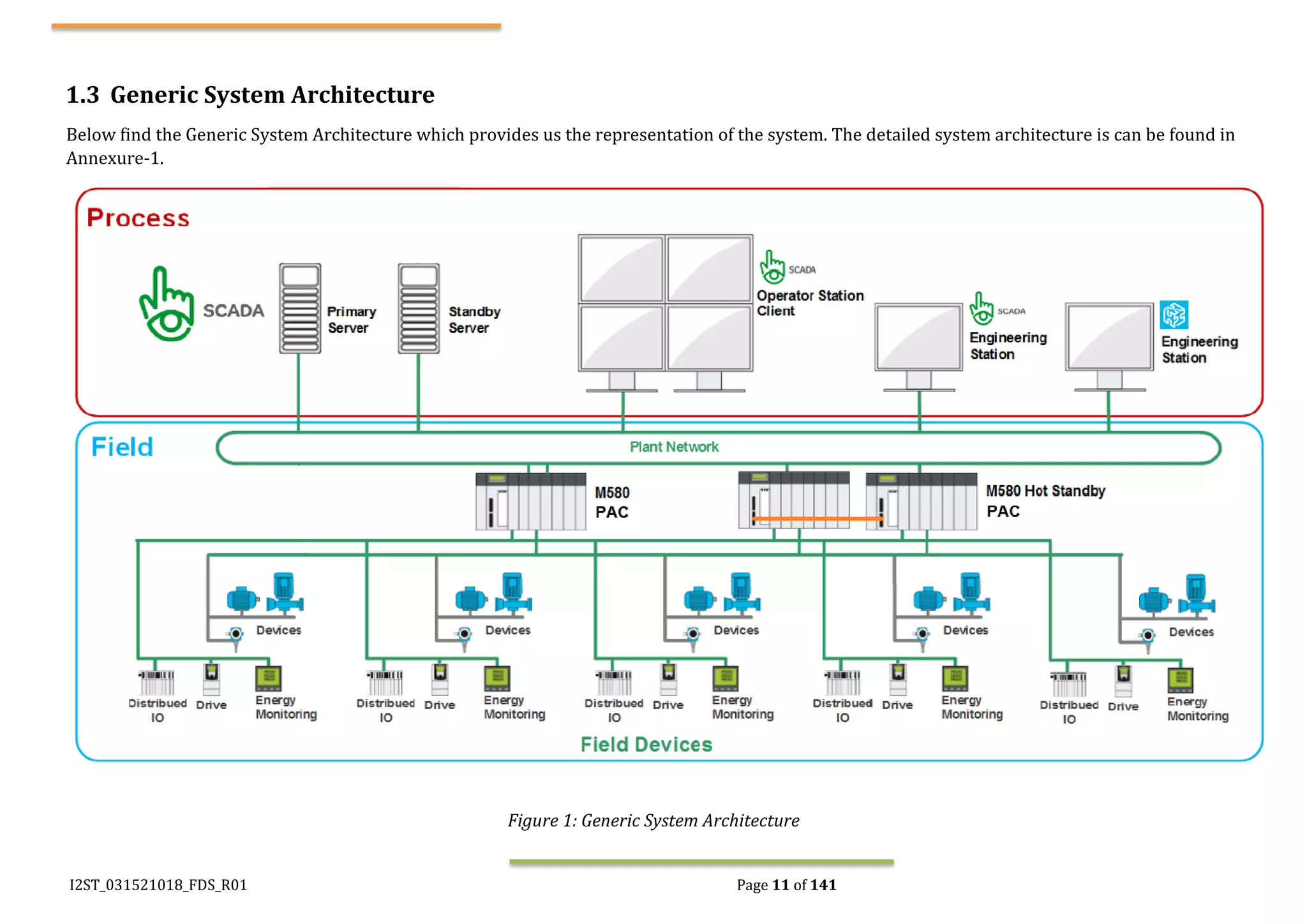
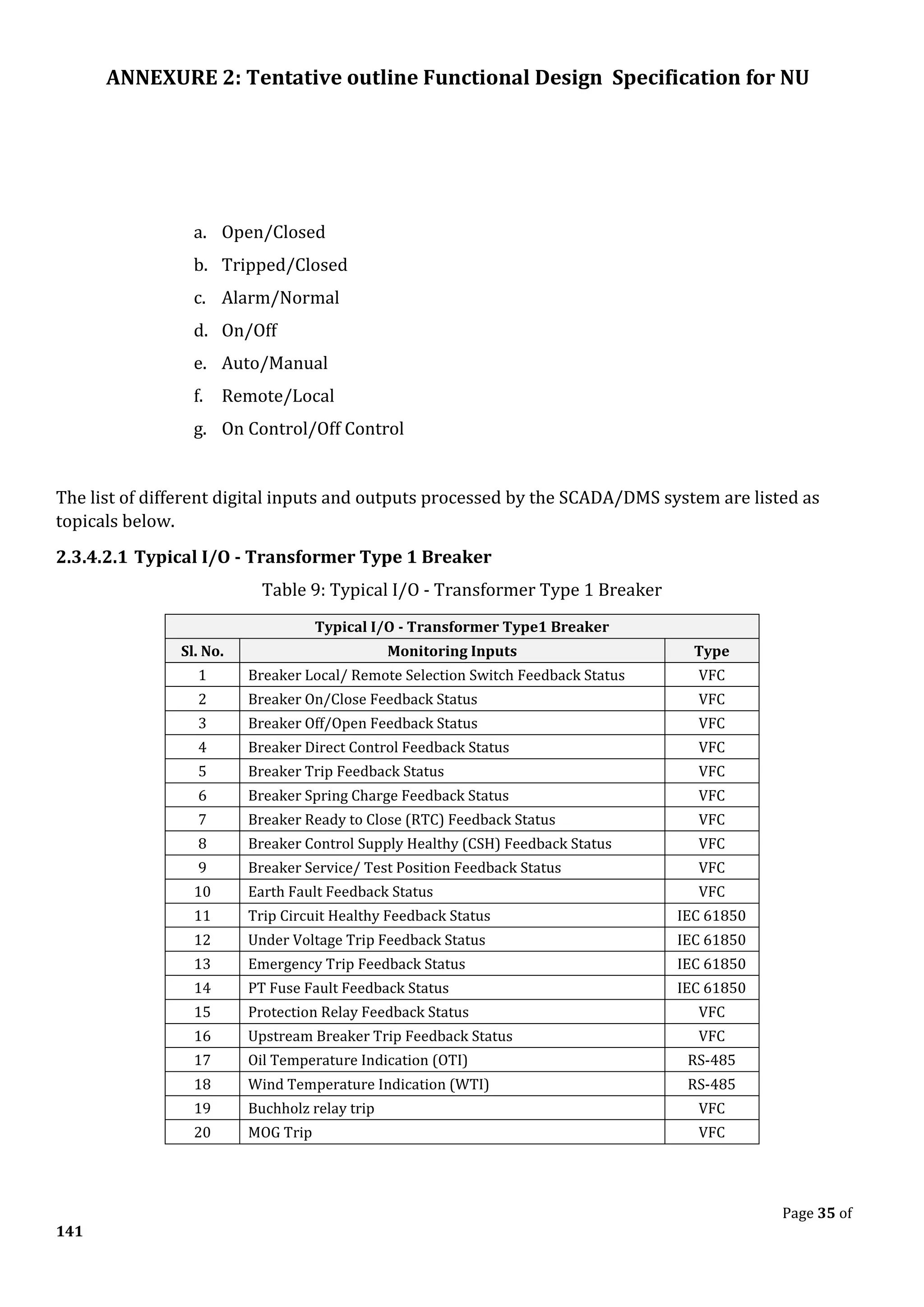
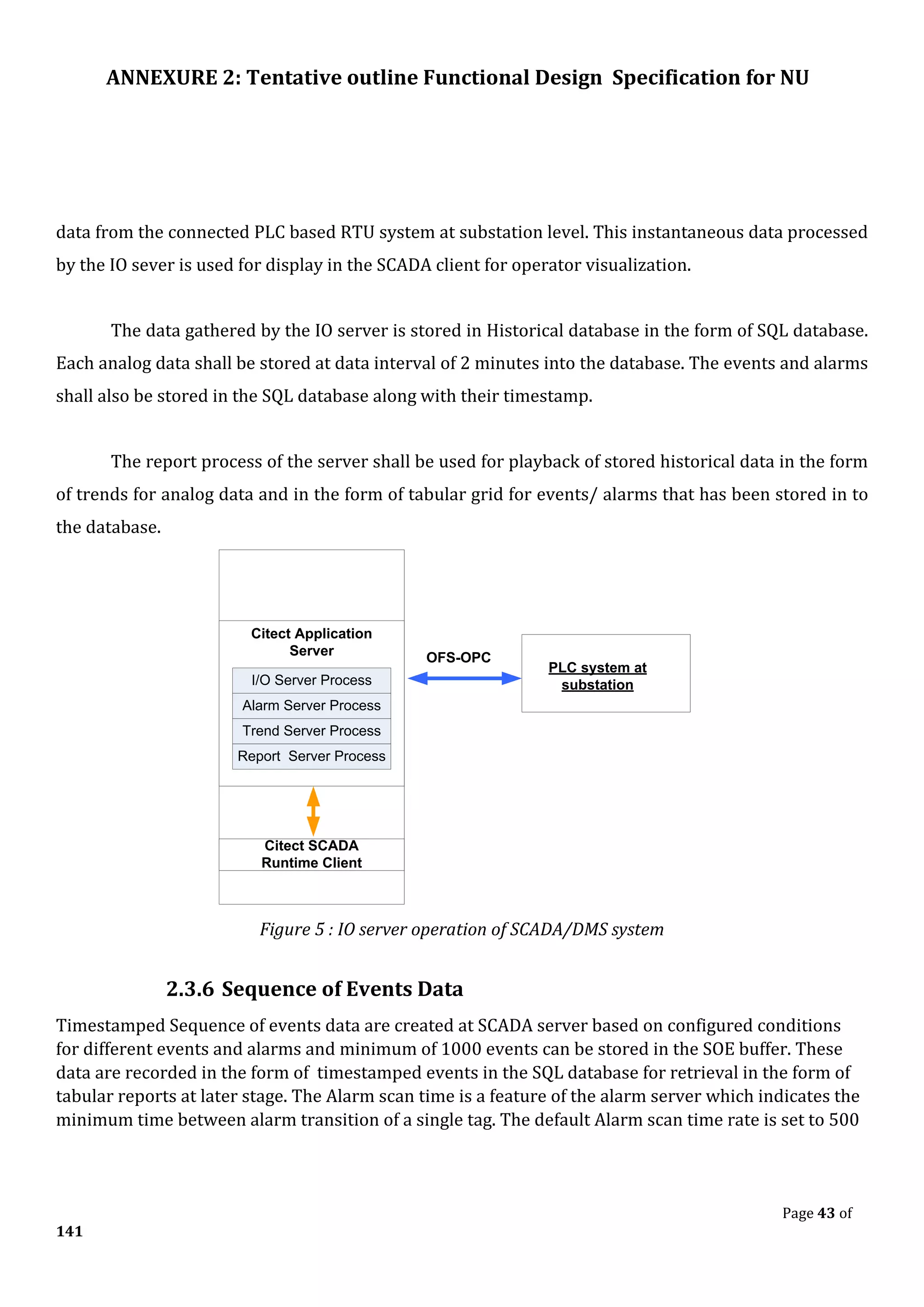
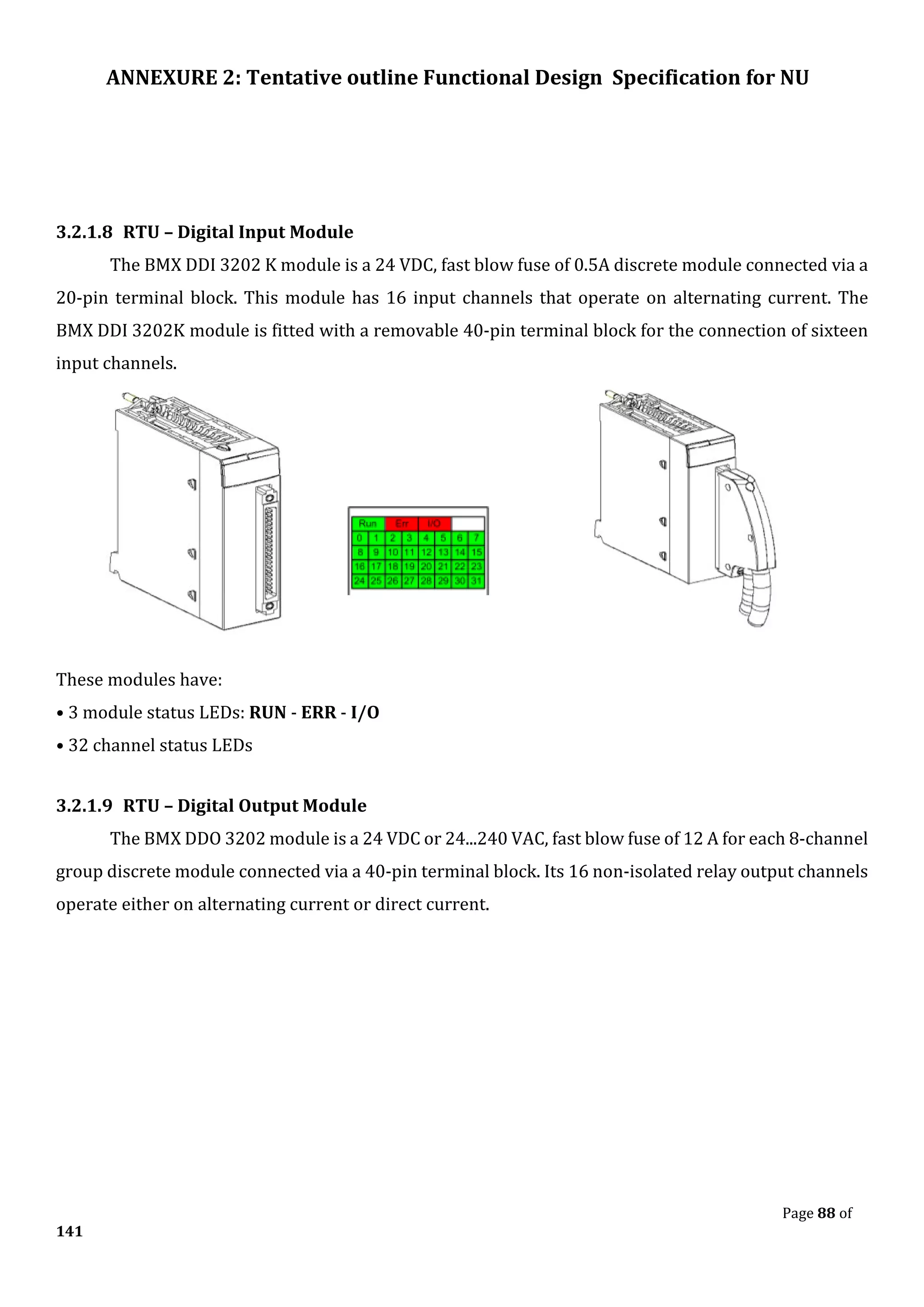
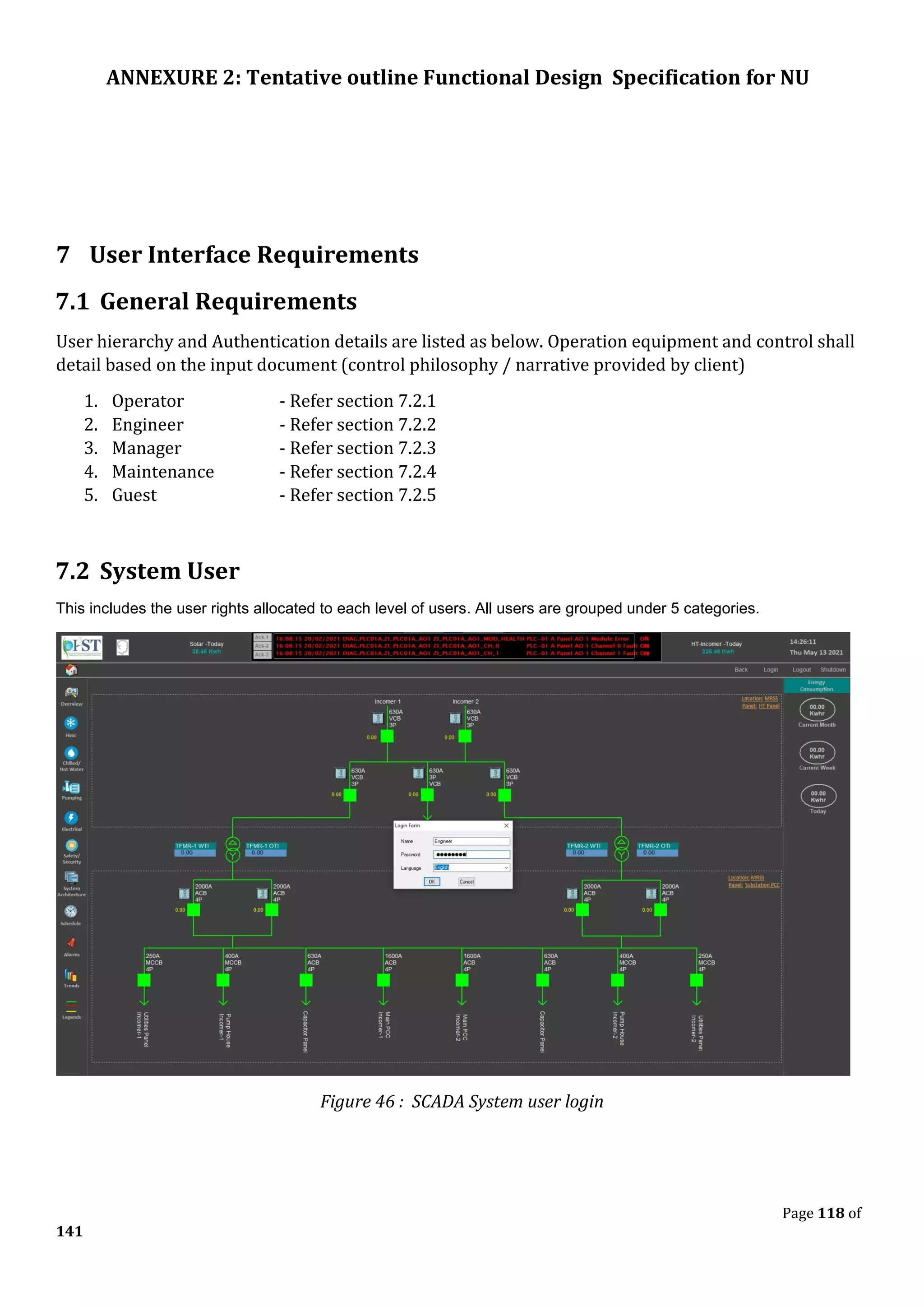
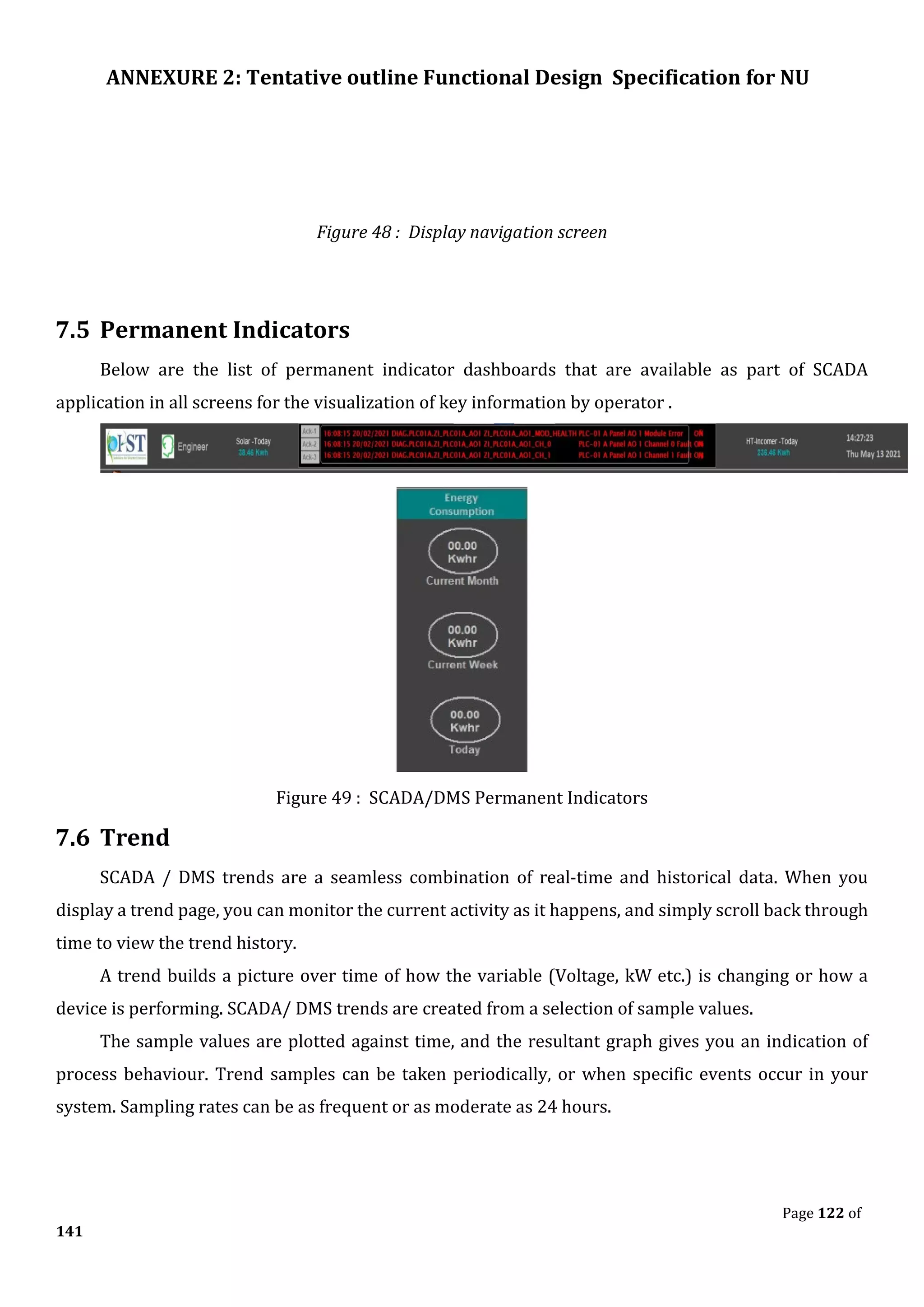
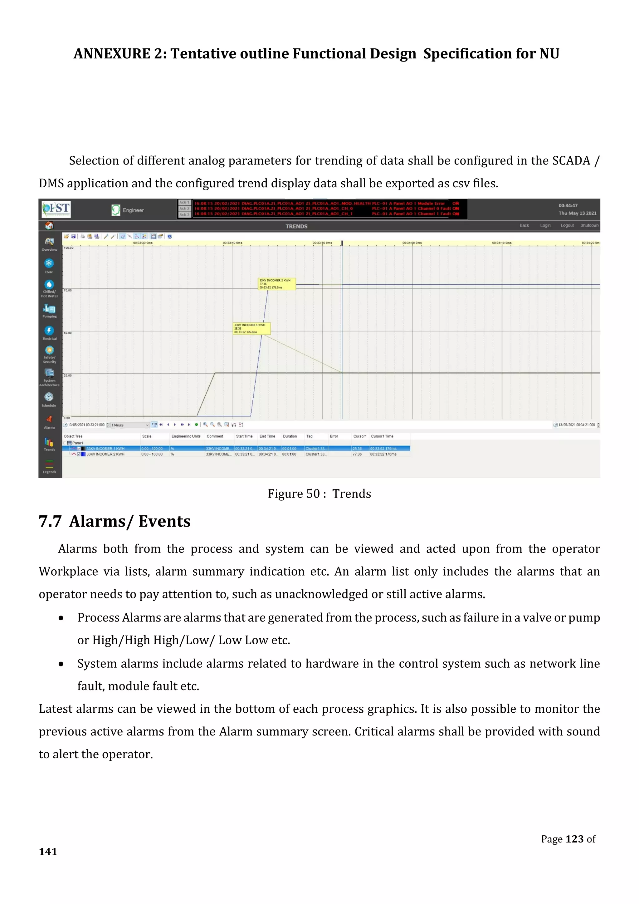
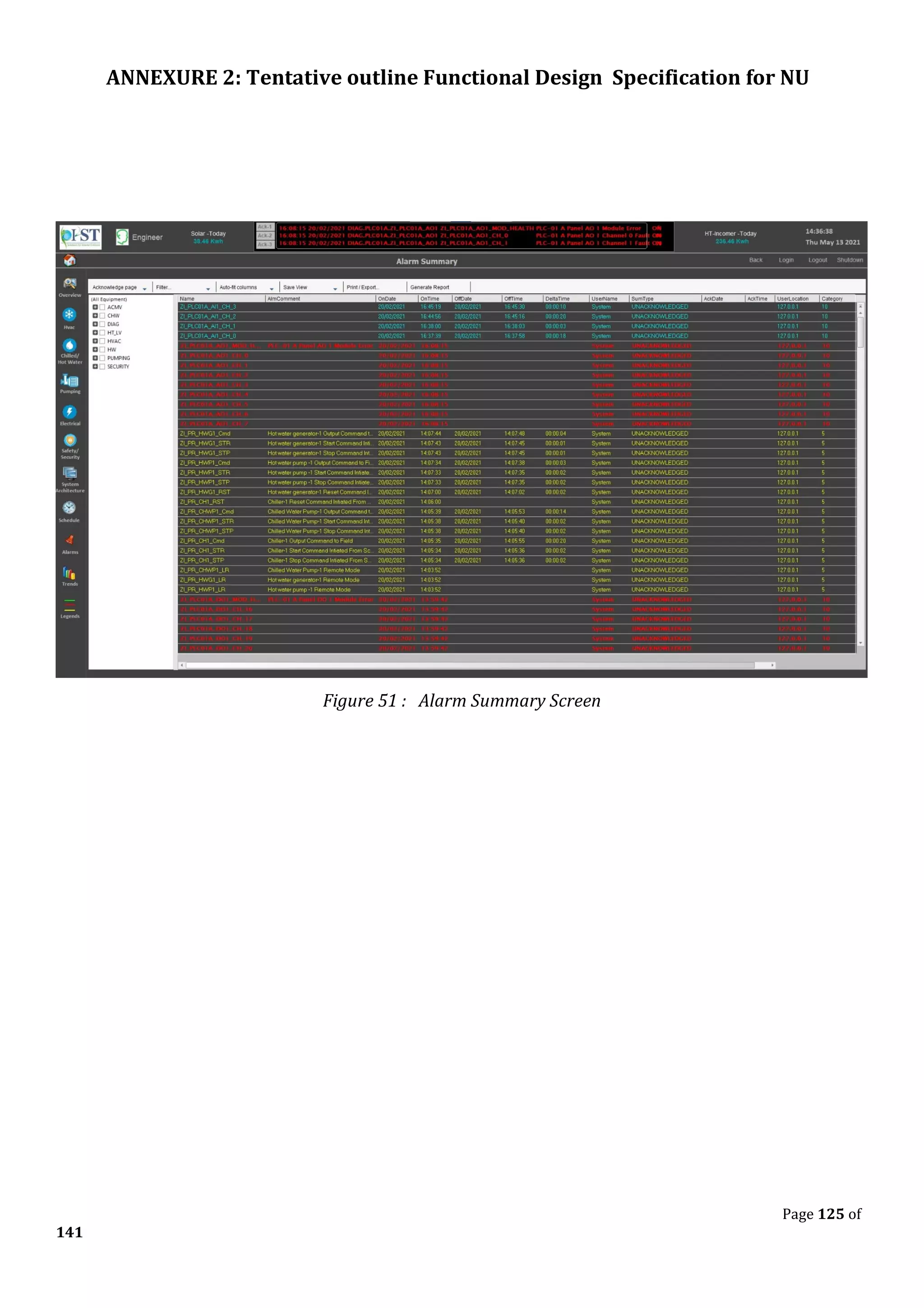
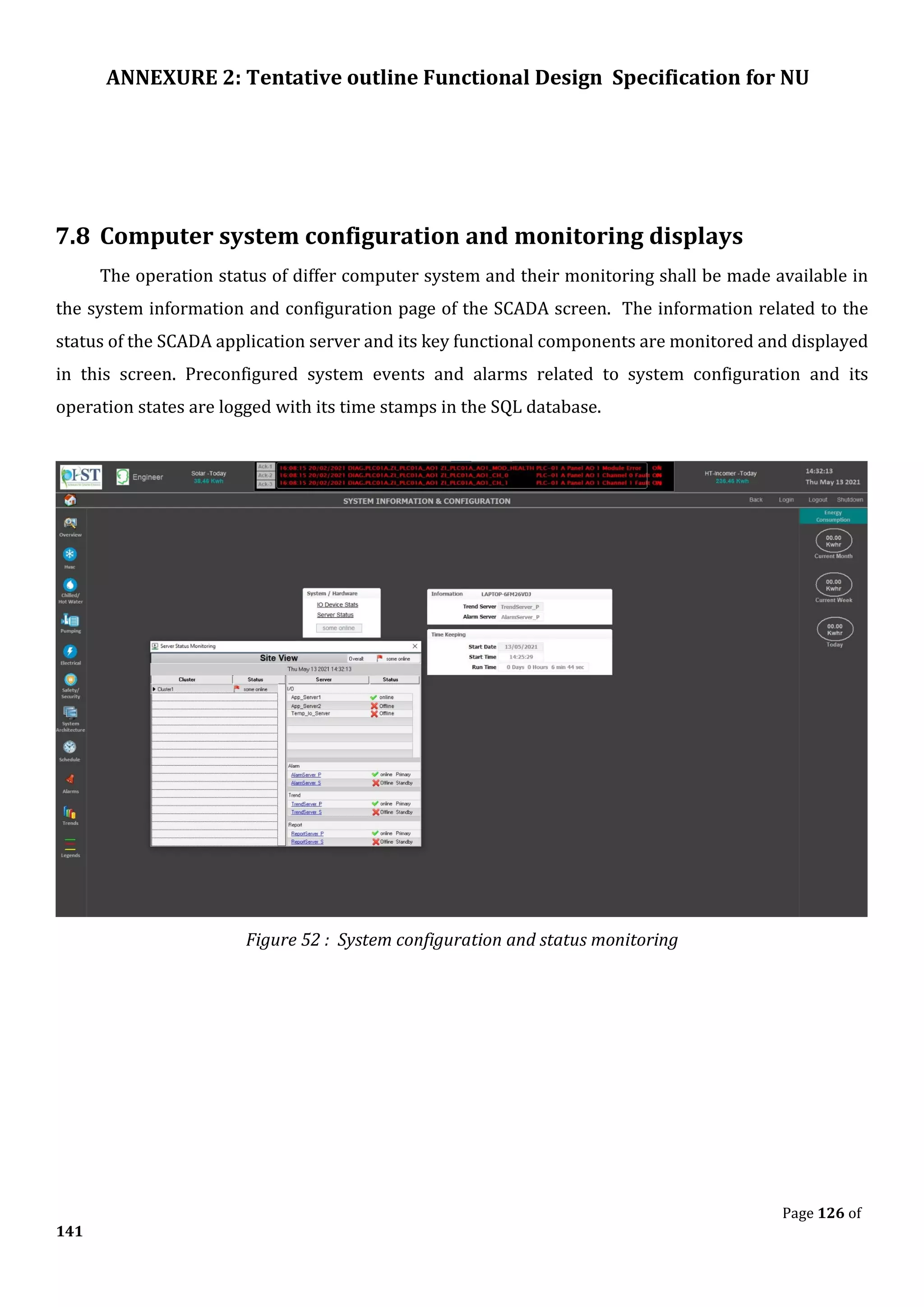
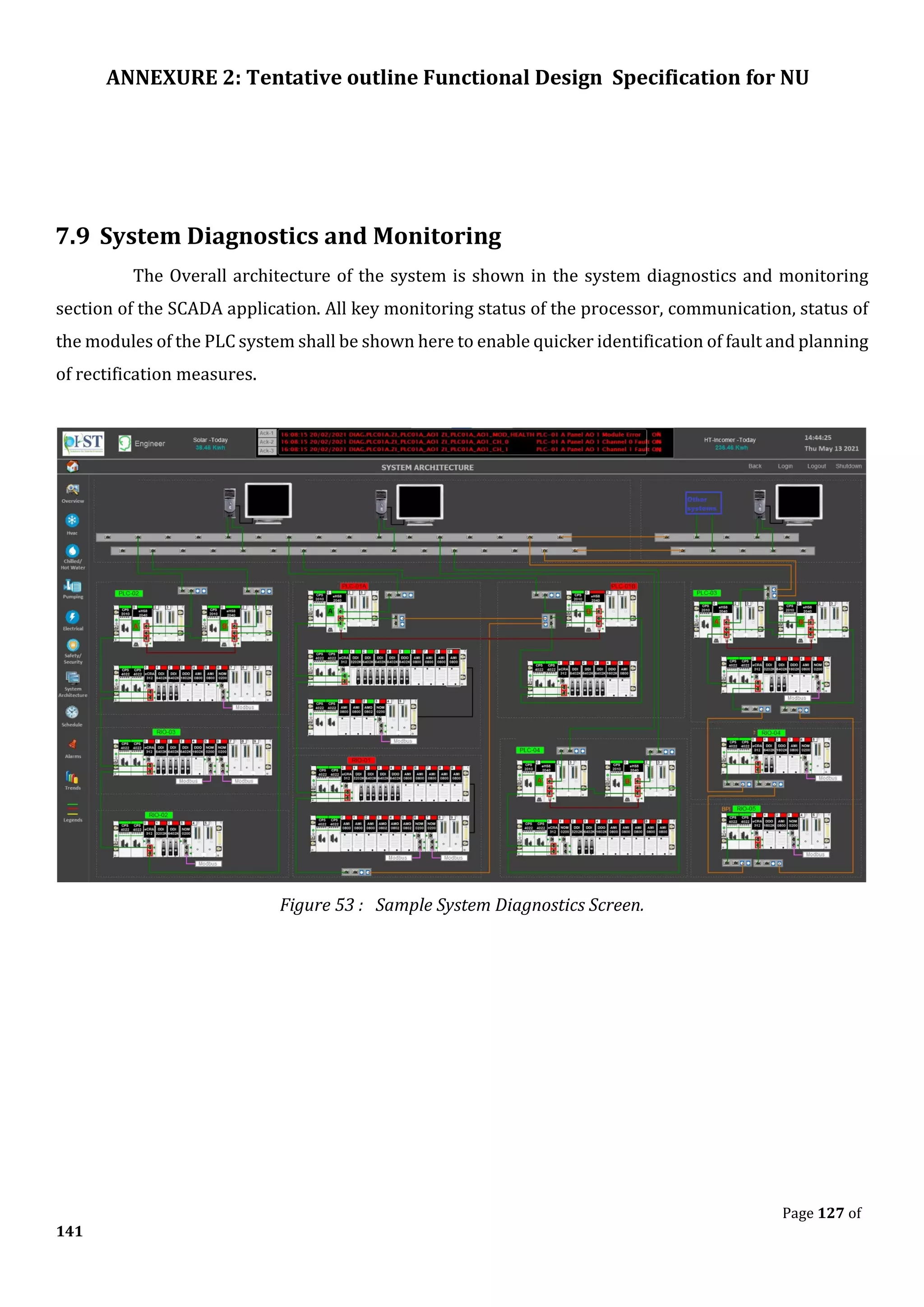
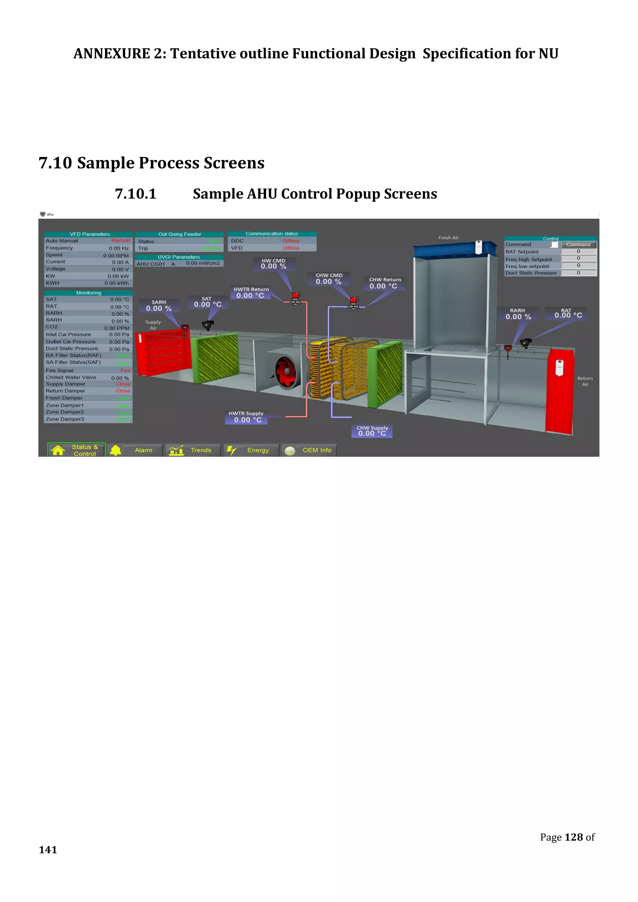
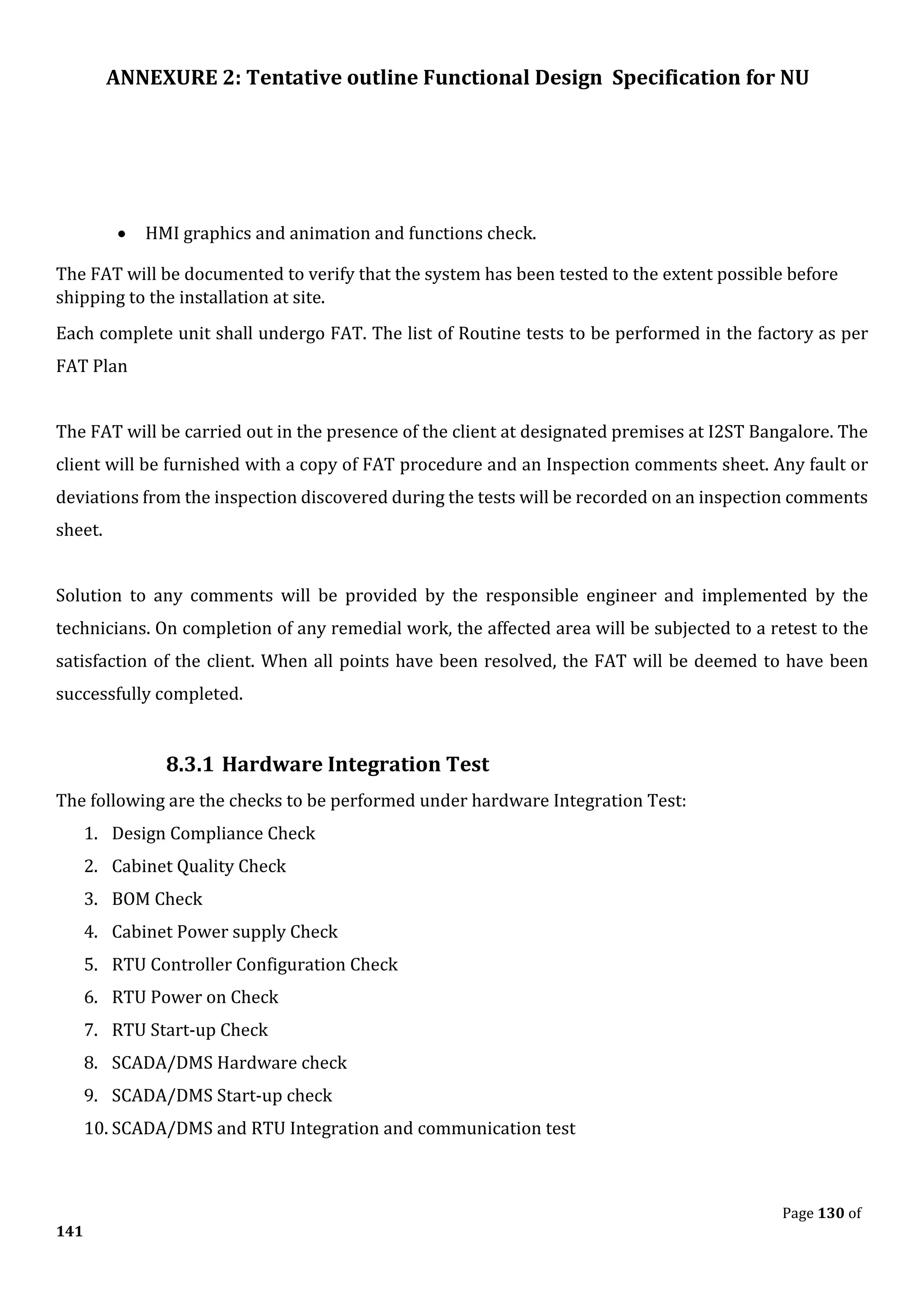
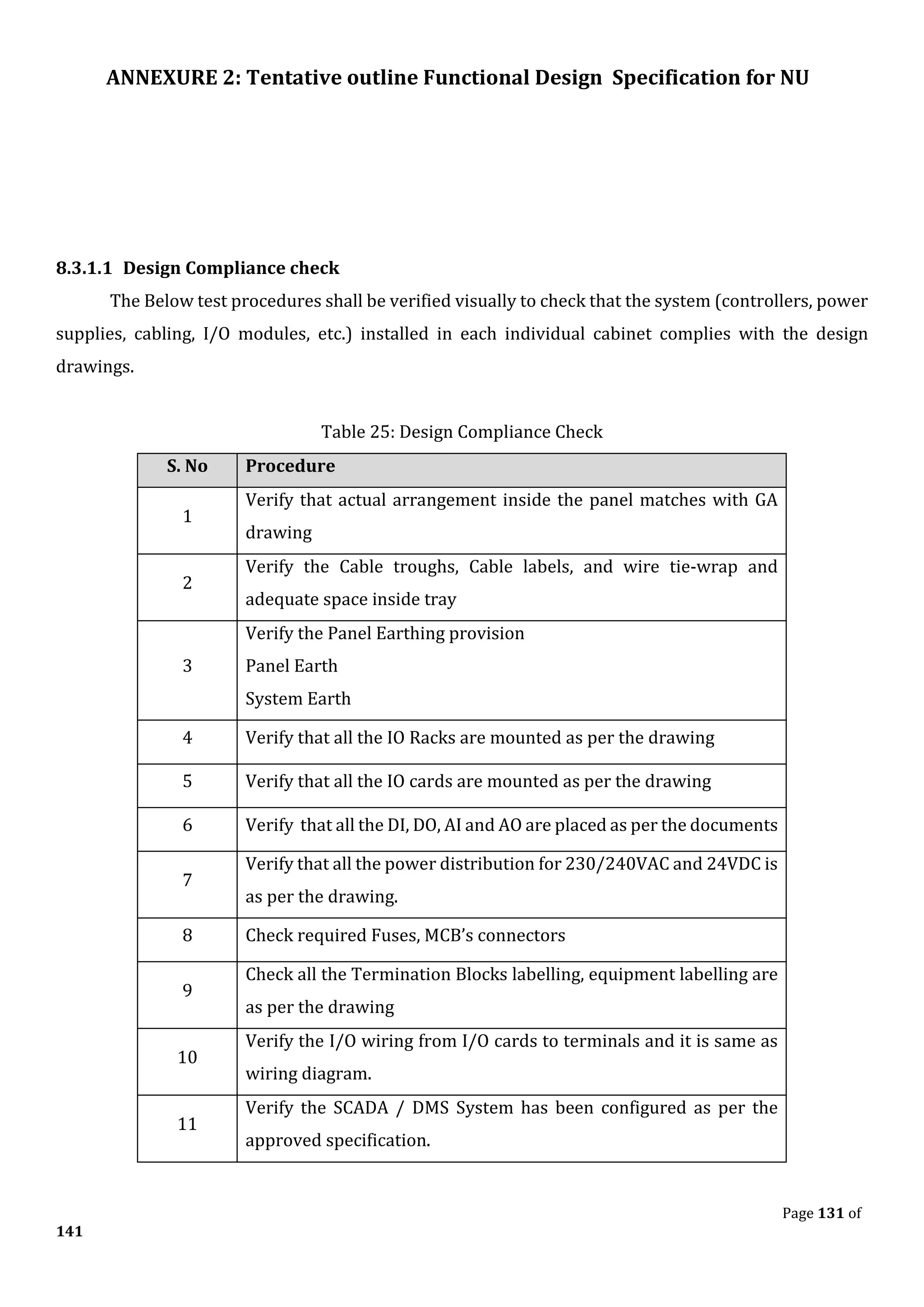
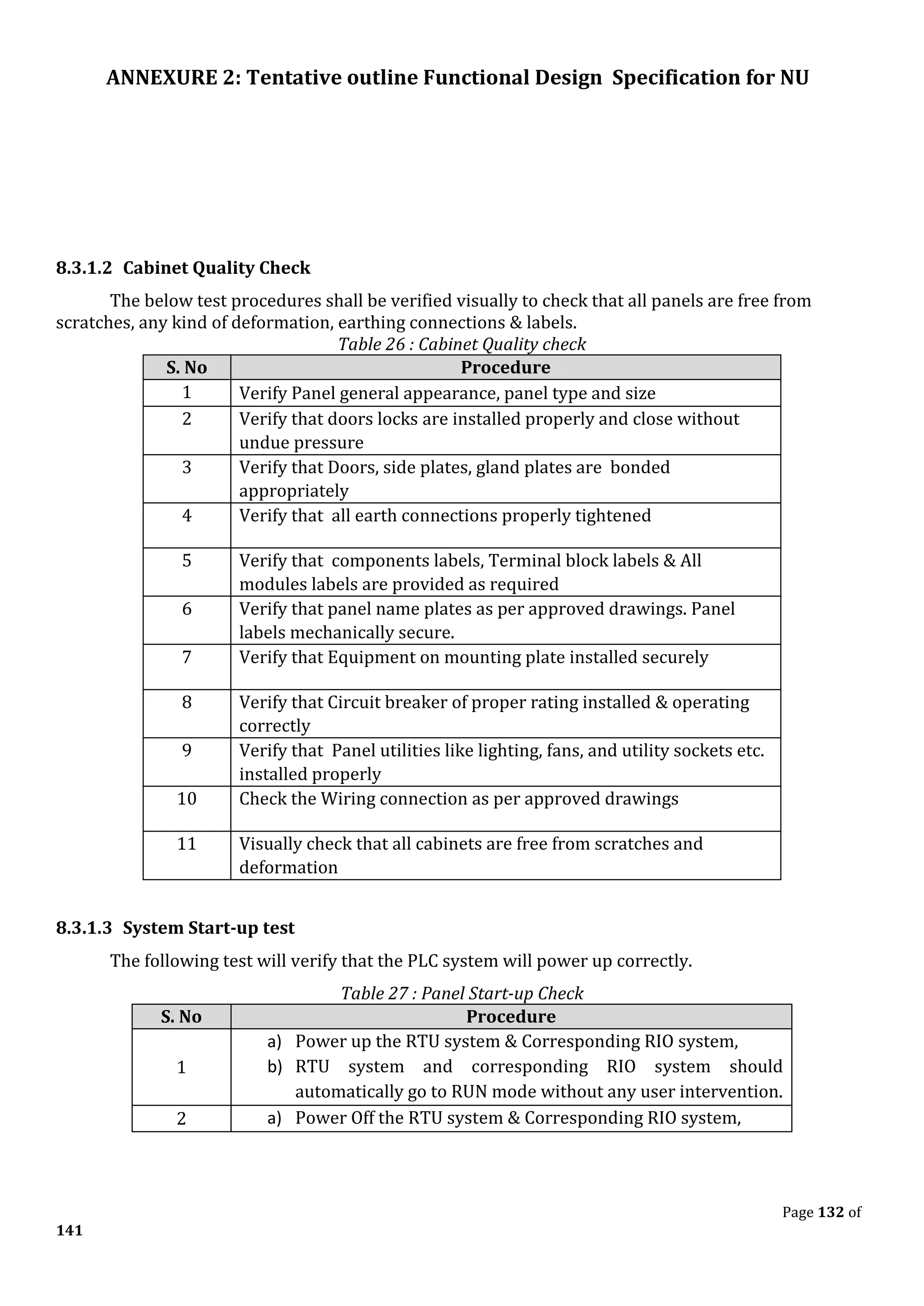
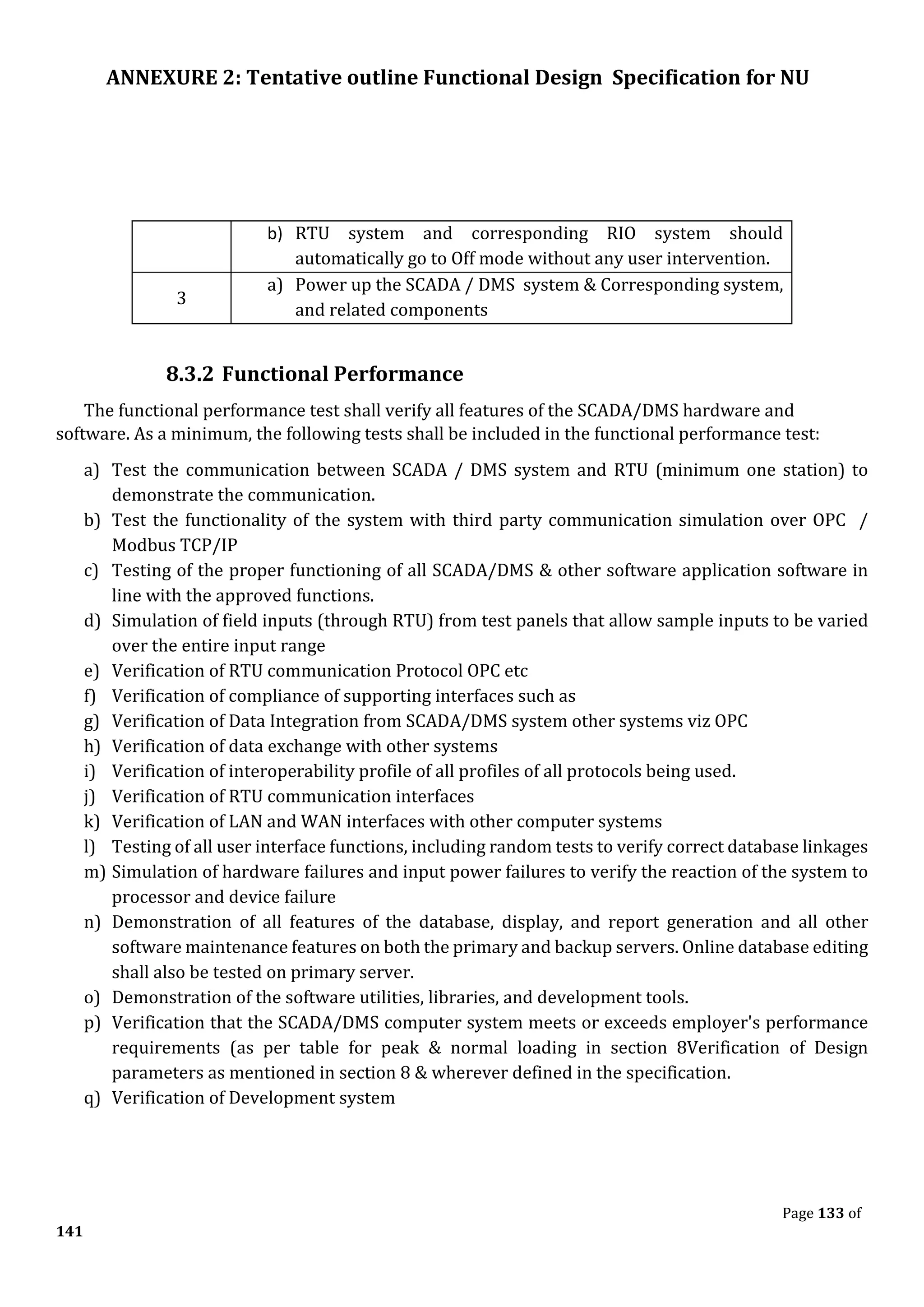
The document outlines the functional design specification for an integrated centralized SCADA and automation system for Nalanda University, including proposed hardware and software systems for the SCADA system at the central command center and RTU systems at substations, with details on system functions, hardware requirements, and functional design of the overall distribution management system.


![Coded Agents – with UiPath SDK + LangGraph [Virtual Hands-on Workshop]](https://cdn.slidesharecdn.com/ss_thumbnails/codedagentsdeck-251215155422-5497c599-thumbnail.jpg?width=640&height=640&fit=bounds)


