New from BookNet Canada for 2024: BNC BiblioShare - Tech Forum 2024
Pid En Un Pic16 F684
1. AN964
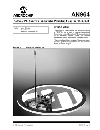
Software PID Control of an Inverted Pendulum Using the PIC16F684
Author: John Charais INTRODUCTION
Ruan Lourens The purpose of this application note is to describe how
Microchip Technology Inc. a PIC16F684 can be used to implement a positional
Proportional-Integral-Derivative (PID) feedback control
in an inherently unstable system. An inverted
pendulum is used to demonstrate this type of control.
The inverted pendulum consists of three main parts:
the base platform, the pendulum and the controller
board, as shown in Figure 1.
FIGURE 1: INVERTED PENDULUM
2004 Microchip Technology Inc. DS00964A-page 1
2. AN964
BASE PLATFORM FIGURE 2: MOTOR
The base platform is a 3-point platform, 2 wheels (one
of which is geared and attached to a DC motor) and an
audio jack. When the DC motor is turned on, the base
platform will rotate around in a circle with the center of
the axis of rotation being the audio jack. The audio jack
serves 2 purposes; first it is used as the axis of rotation
for the base platform and second, it is used to bring
commutated power to the controller board.
PENDULUM
The pendulum is attached to the base platform by a
360° free rotating potentiometer. The pendulum’s base
is attached to the potentiometer in such a fashion that
when the pendulum is balanced (completely vertical),
the potentiometer center tap is biased to VREF/2. For
the rest of this application note Θ will be used to denote
the displacement angle of the pendulum with respect to
the vertical axis.
CONTROLLER BOARD
FIGURE 3: CONTROLLER BOARD
DS00964A-page 2 2004 Microchip Technology Inc.
3. AN964
The controller board has 2 main functions, to measure The desired set point R(t) of this system occurs when
Θ and to drive the DC motor. The power supply needed Θ = 0°. In this state, the pendulum is balanced. Since
to run the system is dictated by the selection of the the desired response of the system is 0°, any angle
motor. The motor is controlled by an H-bridge which is measured other than 0° is the error or Y(t) = E(t).
driven by the PIC16F684 Enhanced Capture/Compare/ In implementing the PID controller, there are 3 terms
PWM Module (ECCP). The outputs of the ECCP are which are based off the error measurement.
connected to FET drivers that produce the proper drive
voltages and reduce the transition times for the FETs in Proportional Term: KPE(t) – where KP is the
the H-bridge. proportional constant
t
There are 5 potentiometers located on the controller Integral Term: KI ∫ E(t)dt – KI is the integral
0
board, 3 of which are used for adjusting the PID con- constant
stants (KP, KI and KD) and one to measure Θ. The fifth Derivative Term: KDdE(t)/dt – KD is the derivative
potentiometer is used in conjunction with the input fil- constant
ter’s reference. The input filter is a low-pass Bessel fil-
ter with a cut-off frequency of 60 Hz and has a voltage EQUATION 1:
gain of 6. A low-pass filter is needed to eliminate any t
high frequency noise on the angle measurement which C(t) = KPE(t) + KI ∫0 E(t)dt + KDdE(t)/dt
the derivative term of the PID controller is extremely
sensitive to. The Bessel filter is used because it has the In this system, the sign of the controller’s output, C(t),
best response to a step function. (Once the pendulum will determine the direction in which the motor will turn.
is balanced, a sudden displacement that causes it to The magnitude of C(t) directly corresponds to the duty
become unbalanced will look like a step function.) The cycle of the PWM in the ECCP module, determining the
cut-off frequency was chosen to be at least twice the speed at which the motor will turn.
expected frequency of the pendulum. The gain of the
filter was chosen to increase the resolution of the Ana-
log-to-Digital (A/D) converter. With the 360° potentiom- PID IN A DIGITAL SYSTEM
eter and a 10-bit A/D converter, with no gain, one LSb Converting over to a digital system, Y(t) is measured by
equals 0.35°. With the gain set to 6, the displacement an A/D converter. In order to implement the PID con-
angle is limited to ±30° which gives a resolution of troller, the PICmicro® microcontroller will have to do
0.059° per LSb. The fifth potentiometer controls the some approximations of integral and derivative terms.
input filter’s reference to produce a true 0° displace- Starting with the derivative term, we can use the
ment angle when the pendulum is vertical. Without this following difference equations for our approximation.
potentiometer, any slight offset angle will cause the
base to slowly increase its speed and eventually take
EQUATION 2:
the system into an unstable state. For more information
on the controller board, see the schematics in dE(t)/dt ~ [E(n)-E(n-1)]/Ts
Appendix A: “Schematics”.
Where E(n) is the current error, E(n-1) is the previous
PID error and TS is our sampling period. Equation 2 is the
approximate slope of the tangent line at E(t) (rise/run).
For the positional PID control system, Figure 4 is used For the integral term use the approximation in
to model the system. Equation 3.
FIGURE 4: PID CONTROL SYSTEM EQUATION 3:
MODEL
∫0 E(t)dt ~ Ts Σ E(n)
N
t
0
R(t) ±E(t) Motor Y(t)
C(t)
Output With these approximations we can rewrite C(t) as
shown in Equation 4.
Feedback EQUATION 4:
C(n) = KPE(n) + KITs Σ E(n) + KD[E(n)- E(n-1)]/Ts
N
R(t) = Reference of desired set point
0
Y(t) = Measured response
E(t) = Error OR
N
C(n) = K(E(n) + (Ts/TI) Σ E(n) + (TD/Ts)[E(n)- E(n-1)])
C(t) = Controller response
0
Where KP = K, KI = K/TI & KD = K TD
2004 Microchip Technology Inc. DS00964A-page 3
4. AN964
MODELING THE INVERTED
PENDULUM With a pendulum length of 0.5 meters and ΘMAX set
to 20° or 0.349 radians.
In order to properly implement the control algorithm,
From Equation 5:
the user needs to look at how the mechanical and elec-
trical systems are going to interface together. Dynamic Θ”MAX = (g/R)Θ
modeling the inverted pendulum is not a simple task. Θ’’MAX = (9.81/0.5)0.349
Here are some of the variables which need to be Θ’’MAX = 6.845 radians/sec2
looked at in order to model the system: Θ’’MAX = 3.425 meters/sec2
• Bases’ position The motor used in this system that meets this criterion
• Bases’ velocity is from MAXX Products, Inc. The model number is
• Bases’ acceleration EPU9, with an 8.6 to 1 gear ratio attached to a 2 inch
wheel. The rated voltage for this motor is 4.8 to 7.2V,
• Bases’ moment of inertia
but for this example the motor will run at 12V. This is
• Bases’ coefficient of friction done to get a better response out of the motor at small
• Bases’ mass duty cycles from the PWM. Running at approximately
• Bases’ length double the designated input voltage is not a concern
• Earth’s gravitational constant because the motor will never be in a constant state
where the duty cycle of the PWM is greater than 50%.
• Pendulum’s position
• Pendulum’s velocity If finding a motor that meets this criterion is difficult,
there are a few solutions. One solution is to decrease
• Pendulum’s moment of inertia
ΘMAX in the software or increase the length of the pen-
• Pendulum’s coefficient of friction dulum; this will reduce the maximum acceleration of the
• Pendulum’s mass pendulum. Another possible solution is to increase the
• Pendulum’s length coefficient of friction between the drive wheel and the
In order to simplify all this, use one simple rule of base. If the motor is of ample size, the coefficient of fric-
thumb. Select a motor (with proper torque, rpm’s and tion of the drive wheel will be the limiting factor in how
gear ratio to the drive wheel) that can accelerate the fast the base can accelerate. Change the coefficient of
base platform as fast as the pendulum can fall. The friction by changing the drive wheel to a different mate-
angular acceleration of the pendulum with respect to rial or add an abrasive surface to the platform.
the displacement angle is: To get a rough estimate of how fast the PID loop needs
to be updated, place an object, similar in length of the
EQUATION 5: pendulum, on end in the palm of one hand and try bal-
ancing it. The object may or may not be possible to bal-
Θ” = (g/R)Θ ance. The shorter the object, the harder it is to balance.
In testing this method, the shortest length balanced for
a sustained period was 0.5 meters in length. Balancing
an object in such a fashion predominantly relies on the
Note: See Appendix B: “Derivation of sense of sight. Since human vision can only process
Equation 5” for the derivation of this information at approximately 30 Hz, 30 Hz will be the
equation. baseline for the minimum speed the control loop needs
Since the acceleration of the pendulum is not constant, to run at.
use the maximum acceleration of the pendulum when The frequency of the PID control loop is also going to
using this rule of thumb. The maximum acceleration of be selected to simplify the math routines. The Integral
the pendulum will occur when Θ is at the largest angle, term, in Equation 3, shows that each error term needs
the controller will try and correct for (ΘMAX). ΘMAX is to be multiplied by the sampling period (which is the
controlled by both hardware and software. The hard- same as dividing by the sampling frequency). By
ware boundary for ΘMAX is set by the gain of the Bessel choosing a sampling frequency in powers of 2’s, a very
Filter; with a gain of 6, the limit is ±30º or ±0.523 fast divide routine can be done by using the right shift
radians. This can be further limited in the software. The command, where each right shift is a divide by 2. It is
software, accompanying this application note, further very similar for the Derivative term, except the left shift
limits ΘMAX to ±20º or ±0.349 radians. This is done to would be used for a multiply by 2. Knowing this, choose
eliminate the possibility of hitting the hardware bound- 256 Hz as the sampling frequency. This is 8 times
ary. faster than the estimated minimum frequency and
should allow plenty of room to vary the length of the
pendulum, if desired.
DS00964A-page 4 2004 Microchip Technology Inc.
5. AN964
C CODE FLOW CHART
The following flow charts show a simplified version of
the C code for the inverted pendulum. For a full
description of the code, see the AN964 Source Code
file.
FIGURE 5: FLOW CHART
Main Routine Interrupt Service Routine
Reset of
Reset TMR0
PIC16F684
Initialization Read Error
Routine Angle
Read KP, KI, KD Set PID Loop
Flag
PID Flag No Error to Yes
set? big?
Yes No
Calculate
Integral Term Error to Yes Clear PID
small? Loop Flag
Limit if too big
or small No
Return Stop PWM,
Calculate Reset terms
Deriv. Term
Limit if too big
or small
Sum terms &
mult. by KP
Set PWM DC
& direction
Shift errors
clear PID flag
2004 Microchip Technology Inc. DS00964A-page 5
6. AN964
SUBTLETIES IN THE SOFTWARE FIGURE 6: C CODE
The interrupt service routine is used to control the //Calculate the differential term
speed of the PID loop. The interrupt service routine is derivative_term = en0 - en3;
set to run off the Timer0 Interrupt. Timer0 is an 8-bit if(derivative_term > 120){
timer that will increment the TMR0 register every derivative_term = 120;
instruction clock. When the TMR0 register overflows, }
if(derivative_term < -120){
the Timer0 Interrupt Flag is set. The speed at which
derivative_term = -120;
the interrupt should occur is every 3.9 milliseconds
}
(1/256 Hz). Since we are using the internal 8 MHz derivative_term = derivative_term * kd;
internal oscillator, we will have a 2 MHz instruction derivative_term =derivative_term>>5;
clock or 0.5 µs per instruction. This yields that the //divide by 32
interrupt should run every 7812 instructions. By set- }
ting the TMR0 prescaler to 32 and reloading 11 into if(derivative_term > 120){
the TMR0 register, in the interrupt service routine, the derivative_term = 120;
Timer0 interrupt occurs every 3.9 milliseconds or }
every 7808 instructions (255-11)*32. if(derivative_term> -120){
derivative_term = -120;
As stated previously in this application note, there are }
2 basic form of the PID that can be implemented and
they are:
When the approximation was made for the derivative
term, it stated that the approximation would be:
EQUATION 6:
Ν EQUATION 7:
C(n) = KPE(n) + KITs Σ0
E(n) + KD[E(n)- E(n-1)]/TS
KDdE(t)/dt = TD [E(n)- E(n-1)]/Ts
OR Where TD = KD/KP
Ν
C(n) = K(E(n) + (1/TI) Σ0
E(n) + TD[E(n)- E(n-1)]/TS
By reviewing the code in Figure 6, one can determine
that the approximation, shown in Equation 7, is not the
Where KP = K, KI = K/TI & KD = K TD approximation used. The actual equation that was used
for calculating the derivative term is as follows:
The later is used because a change in the proportional
constant will not affect the pole response of the control- EQUATION 8:
ler. If variations in the supply voltages were expected,
such as battery powered applications, it would be pos- KDdE(t)/dt = KD [E(n)- E(n-3)]/32
sible to change the proportional constant on the fly to
compensate for these supply variations. The relation- Equation 8 more accurately written would be:
ship to the proportional constant and the supply voltage
to the motor would be inversely proportional. EQUATION 9:
The derivative term is crucial in order to bring the inher-
ently unstable system into stability. In any PID control KDdE(t) = TD[E(n)- E(n-3)]/(X•3•Ts)
the derivative terms acts as an anticipator. By checking =KD[E(n) -E(n-3)]/(KP•X•3•TS)
the current error against the previous error, the control-
ler can tell if the error term is getting bigger or smaller. Where X is an unknown scaling factor
If the error term is getting larger, the derivative term
adds to the output of the controller much like that of the
proportional and integral terms, but to a lesser effect. If
the error term is getting smaller, this term will subtract
from the output of the control in anticipation of an over-
shoot condition. Without the derivative term the system
will always be unstable because there is no way to
compensate for the overshoot condition. The following
is the actual C code used to calculate the derivative
term.
DS00964A-page 6 2004 Microchip Technology Inc.
7. AN964
With a 10-bit A/D, KD is measured as an integer 7. Start increasing the KI the same way as KP until
between 0 and 1023. The X term allows for a fractional the pendulum can be balanced for several sec-
representation of KD, not just a integer. (Similar scaling onds under a constant oscillating condition.
factors are also used when calculating the integral and When the KI is added, the base will now accel-
proportional terms). The 3*TS comes from the fact that erate faster than the pendulum causing Θ to
we are tripling our sampling period by using E(n) – E(n- change from a positive angle to a negative angle
3) not E(n) – E(n-1). Why use E(n) – E(n-3) instead of (or vice versa). The pendulum will begin to fall
E(n) – E(n-1)? The main reason for doing this is to limit backwards. The base should change directions
the variation in the error angle measurement. There will and, again, accelerate faster than the pendulum
always be an amount of uncertainty associated with the until Θ changes signs and the whole cycle
error measurement, some of which can be attributed to repeats. This is known as the Overshoot
A/D error, Bessel filter throughput, mechanical vibra- condition.
tion, etc. Since the uncertainty of the error measure- 8. Increase KD in the same manner as KP and Ki
ments will be the same for all error terms, this until the Overshoot condition is gone and the
uncertainty can be decreased by effectively tripling the pendulum remains balanced.
sampling period. The real key is that the derivative term 9. Once all overshoot is gone, the PID controller is
is still updated at 256 Hz rate. Doing so gives the ben- tuned.
efit of the slower rate a more accurate derivative term,
but at the desired faster sampling rate. The side affect
of doing this is adding approximately 4 milliseconds of CODE CONVERSION TO ASSEMBLY
lag to the derivative term, which in this case is accept-
For those who prefer to program in assembly, there is
able. KP*X*3*TS has been precalculated to be 32 to
an assembly file which can be used also. When pro-
increase the speed of the PID loop.
gramming in assembly, it is essential to make sure that
the results of the math functions have the proper sign
TUNING THE PID CONTROLLER and the math registers never overflow. In order to
speed up the PID loop, all the multiply routines have
Use the following steps to tune the PID constants: been limited to an 8x8 signed multiply routine with a 16-
1. Turn the KP, KI and KD potentiometers counter bit signed result. To do this, Θ was measured by the 10-
clockwise as far as they will turn. This sets all the bit A/D with the 2 LSb being ignored. The 8-bit A/D
constants to zero. result was then converted to an 8-bit signed number by
2. Power the device using a 12V (minimum of a 3 adding 128 decimal and ignoring the carry flag. The
amp) power supply. constants, KP, KI and KD are all limited to a positive 8-
3. Holding the Reset button down, lift the pendu- bit signed number, or 0-127. Other than these 2 key
lum to the vertical position and release the changes, the assembly program follows the same flow
Reset button and pendulum at the same time. chart as the C code.
4. The pendulum should free fall and the base will Note: By limiting the multiply routines to 8x8 bit
not move. This verifies that all constants are signed math, the Assembly code can exe-
properly read as zeros. cute the PID loop in approximately 215 µs
5. Increase the KP constant by turning the potenti- where as the C code takes 1.4 ms.
ometer counter clockwise and repeat step 3.
6. Keep repeating steps 3-5 until there is a little CONCLUSION
oscillation in the base. If the KP term is too small,
the base platform will chase the top of the pen- By using the PIC16F684 device’s ECCP and A/D mod-
dulum while Θ continues to increase. KP will be ules we are able to demonstrate how to implement a
too large if the drive wheel breaks free or the positional PID controller to bring an inherently unstable
base oscillates at a high rate of speed. system into stability. The keys to implementing this con-
trol is to have a basic understanding of the mechanical
system, and identifying the derivative term would be a
critical factor in the overall stability of the system. The
other keys, with respect to the software, were making
sure our registers never overflow, and picking the
frequency of the PID loop that is a power of 2 so we
could have a fast multiply and divide routine using the
left and right shift.
2004 Microchip Technology Inc. DS00964A-page 7
8. U3 R5
SENSOR
+5_SWITCHED 1 14 1K
VDD VSS FIGURE 7:
2 13
C9 BUTTON RA5/OSC1 RA0/AN0 ICSPDATA
3 12
DS00964A-page 8
100 nF RA4/OSC2 RA1/AN1 ICSPCLK
AN964
4 11
APPENDIX A:
MCLR RA3/MCLR RA2/AN2 P-POT
5 10
P1A RC5/ECCP RC0/AN4 I-POT
6 9
P1B RC4 RC1/AN5 D-POT
7 8
P1C RC3/AN7 RC2/AN6 P1D
PIC16F684/P
+15V +15V
C1 C8
SCHEMATICS
100 nF 100 nF
+15V +15V
3 Q1:B +15V +15V Q2:B 3 IRF7389 6
6 C7 100 nF 7 2
2 7 P1C
P1A +15V +15V 4 U2:A
4
C2 C6 100 pF TC4428A 3 R3
R1 3 U1:A C5
TC4428A 6 5 10 pF 10 pF 5 6 100 kΩ
100 kΩ D2
BAT54S D3
IRF7389 BAT54S
MOTOR
C3 C4
8 7 Q1:A 10 pF 10 pF Q2:A 7 8
IRF7389 IRF7389 U2:B
4 5 2 1 2 4
P1B 2 5 P1D
U1:B
R2 TC4428A TC4428A R4
1 J1 1
100 kΩ 100 kΩ
Note 1: Unless otherwise specified, resistance values are in Ω. Resistors are 5% tolerance. Capacitance values are in µF.
2: Device names and numbers shown here are for reference only and may differ from the actual number.
3: Items labeled with “A” are unpopulated, “B” are socketed but not populated, and “C” are socketed and populated.
2004 Microchip Technology Inc.
10. AN964
APPENDIX B: DERIVATION OF Using 2 unit vectors, i and j to represent the horizontal
and vertical vectors respectively, yields the following
EQUATION 5
equations for the pendulum.
The pendulum’s motion is described in this appendix
with one assumption. The assumption is that the EQUATION B-1:
pendulum is modeled as a point mass at the end of a
massless rod. Position = RsinΘi +RcosΘj
Where R is the length of the pendulum
FIGURE 9: PENDULUM FREE BODY
DIAGRAM
The pendulum’s angular velocity is the derivative of the
j position with respect to Θ.
EQUATION B-2:
Θ
i Velocity = RΘ’cosΘi – RΘ’sinΘj
mg
The pendulum’s angular acceleration is the derivative
T of the angular velocity w.r.t. Θ.
EQUATION B-3:
Acceleration = (RΘ”cosΘi – RΘ’2sinΘi) – (RΘ”sinΘj + RΘ’2cosΘj)
= R(Θ”cosΘi – Θ”sinΘj – Θ’2sinΘi – Θ’2cosΘj)
From Newton’s second law of motion, F = ma where
the mass is the point mass of the pendulum and the
accelerations is the angular acceleration of Pendulum,
this yields Equation 4.
EQUATION B-4:
Force = mR(Θ”cosΘ i – Θ’’sinΘj – Θ’2sinΘi – Θ’2cosΘj)
With a free body diagram we can see that there are 2
forces acting on the pendulum, the tension from the rod
and the force of gravity. This free body diagram yields
the following equation.
EQUATION B-5:
Force = TsinΘ i + TcosΘ j – mgj
DS00964A-page 10 2004 Microchip Technology Inc.
11. AN964
Equate Equation B-4 and Equation B-5:
EQUATION B-6:
TsinΘ i + TcosΘj – mgj = m R(Θ”cosΘ i – Θ”sinΘ j – Θ’2sinΘi – Θ’2cosΘj)
Now separate into 2 different vectors equations and
eliminate the vector notation.
EQUATION B-7: (i Vector)
TsinΘ = m RΘ”cosΘ – mRΘ’2sinΘ
EQUATION B-8: (j Vector)
TcosΘ – mg = -m RΘ”sinΘ – mRΘ’2cosΘ
Use these two simultaneous equations to eliminate the
unknown T.
Multiply Equation B-7 by cosΘ.
EQUATION B-9:
TsinΘcosΘ = m RΘ”cos2Θ – mRΘ’2sinΘcosΘ
Multiply Equation B-8 by sinΘ.
EQUATION B-10:
TsinΘcosΘ – mgsinΘ = -m RΘ”sin2Θ – mRΘ’2sinΘcosΘ
Moving -mgsinΘ to the other side.
EQUATION B-11:
TsinΘcosΘ = mgsinΘ – mRΘ”sin2Θ – mRΘ’2sinΘcosΘ
Equate Equation B-9 and Equation B-11.
EQUATION B-12:
m RΘ”cos2Θ – mRΘ’2sinΘcosΘ = mgsinΘ – mRΘ”sin2Θ – mRΘ’2sinΘcosΘ
Divide by each side by mR.
EQUATION B-13:
Θ”cos2Θ – Θ’2sinΘcosΘ = (g/R)sinΘ – Θ”sin2Θ – Θ’2sinΘcosΘ
Collect like term.
2004 Microchip Technology Inc. DS00964A-page 11
12. AN964
EQUATION B-14:
Θ”(cos2Θ + sin2Θ) = (g/R)sinΘ
By trigonometric definition cos2Θ + sin2Θ = 1 which
yields Equation B-15.
EQUATION B-15:
Θ” = (g/R)sinΘ
Using the small angle approximation where sinΘ = Θ
yields.
EQUATION B-16:
Θ” = (g/R)Θ
DS00964A-page 12 2004 Microchip Technology Inc.