Downloaded 209 times


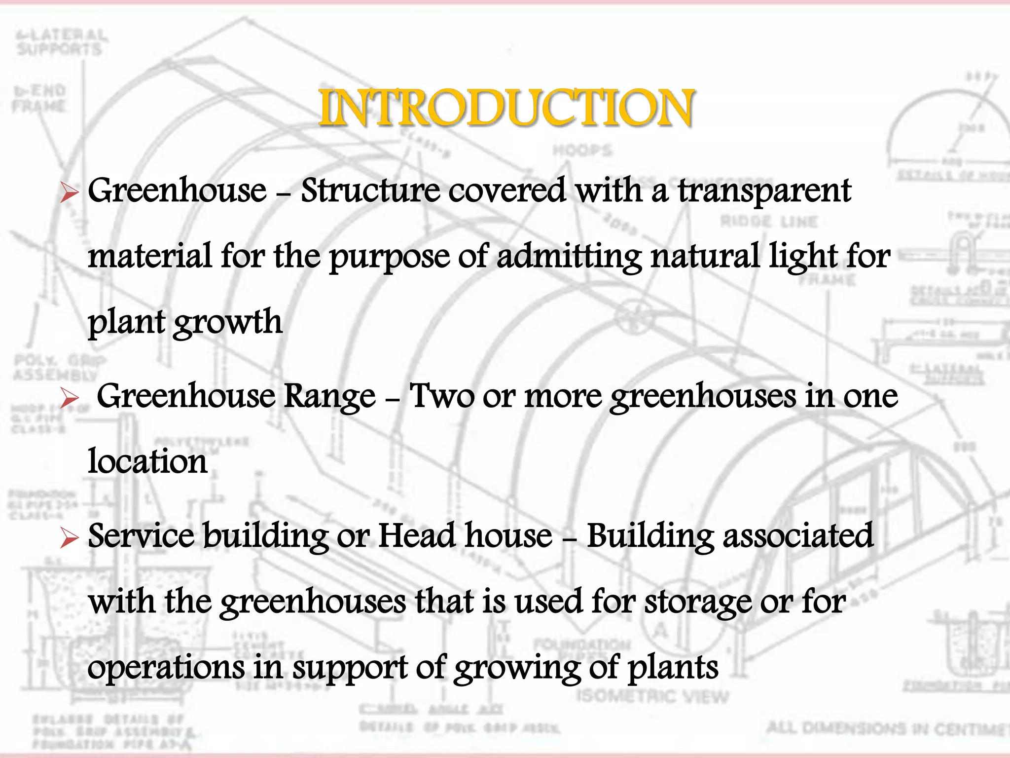


1. The document describes the process of constructing a pipe frame greenhouse with dimensions of 4m x 20m. 2. Key materials needed include galvanized steel pipes, polygrip channels, concrete, and UV-stabilized polyethylene film. 3. Construction involves laying the foundation pipes, assembling the polygrip structure, adding hoops and ridge lines, and stretching the polyethylene film over the frame.


