SlideShare a Scribd company logo
1 of 18
Download to read offline
CHAPTER 5
Main Types of High – Head Power Plant Developments
Power plants operating under a head higher than 50 m may be termed as high-head power
plants. Three main types of high-head power developments may be discerned.
A) Diversion Canal Type Plant
Figure. General layout and profile of a high-head diversion
canal development
The main parts of a high-head diversion canal type plant are:
1) the weir,
2) the canal intake,
3) the head race,
4) the headpond with spillway and gate or valve chamber,
5) the penstock,
6) the powerhouse,
7) the tailrace.
Prof. Dr. Atıl BULU1
B) Plants Fed by a Pressure Tunnel
Figure. General layout and profile of a pressure tunnel development
1) the dam (sometimes only weir),
2) the intake or headworks,
3) the pressure tunnel,
4) the surge tank,
5) the penstock,
6) the power house,
7) the tailrace.
The tunnel intake should be located close to the bottom of the reservoir to ensure the greatest
effective storage volume. Under certain topograhic and geologic conditions, the conveyance
of water through a tunnel under the dividing range may, even in case of low dams, be
preferable to building a long, meandering power canal. Since here the tunnel is not necessarily
a pressure conduit, free-surface flow conditions may prevail therein. Such arrangements
should be regarded as diversion canal type developments.
C) Plants with Concentrated Fall
Developments, where the powerhouse is located close to, or within, a high dam or high-head
river barrage, constitute the third main type of high-head installations. This arrangement,
which could be termed plant with concentrated fall, or valley dam station, is essentially
similar to that of low-head run-of-river plants. The head for the power station approaches the
height of the dam.
Prof. Dr. Atıl BULU2
Figure. Development with the powerhouse located at the toe of the dam
(plant with concentrated fall)
The three main parts of this type of power plants:
1) the water intake (generally built on the upstream face of the dam),
2) the pressure conduit (generally transversing the dam body, sometimes bypassing the
dam adjacent rock),
3) the powerhouse.
The output of diversion canal developments is closely governed by the discharge available in
the river, while the small storage capacity created by the low weir is sufficient to meet daily
fluctuations in load only. This type may be called as high-head run-of-river plant. The other
two types may be referred to as reservoir plants. Pressure tunnel developments are valuable
for those fed from a large reservoir under high head.
Free Surface Intakes
Settling basins and sand traps are very important for high-head water power plants and they
should designed on the basis of hydraulic computations. Suspended load, especially sharp
edged fine sand transported by mountain streams causes rapid wear of the penstock and steel
parts of the turbines. Water flowing at high velocity and carrying heavy sediment load attacks
the lining of power canal and power channels.
Scratch effects become generally more pronounced with increasing head, therefore, in case of
heads higher than 100 m, sand should be carefully settled out and with heads higher than 200
m even the greatest part of silt fraction should be retained.
The main parts of an intake are:
1) the inlet section including the sill and coarse rack,
2) the inlet gate and transition section,
3) the settling basin and sand flushing canal.
Prof. Dr. Atıl BULU3
Figure. General arrangement of intake
Before the inlet section of the intake a bed load deflecting apron should be applied permitting
a periodical flushing of bed load hold by the sill. The apron extends to the flushing gate of the
weir.
Protection against Silting
In preventing entrance of bed load, or rather in promoting a desilting effect at the inlet
section, in protecting both inlet and canal against sedimentation, the proper choice of intake
site is of vital importance.
Prof. Dr. Atıl BULU4
Changes in the angle of diversion (the angle between the outside wall of the intake structure
and the direction of main flow) hardly affect the quantity of sediment entering the canal. More
than 90% of transported matter enters the diversion canal branching off at an angle of 300
–
900
from the main course, yet carrying only half of the main discharge. At the same time it
can be seen that the angle of diversion has no significant effect upon silting conditions.
The curve shown above illustrates the distribution of discharges and silt quantities for a 300
angle of diversion. A balanced (50 – 50 per cent) distribution of silt is attained only if some
25% of the original discharge is allowed to enter the canal. If the discharge carried by the
diversion canal exceeds 60%, the entire sediment load enters to the branch canal.
Hydrodynamical considerations will yield a very simple explanation for the above
phenomenon, that in case of diversion from a straight stretch, the flow entering the power
canal carries extremely great quantities of bed load. The velocity component opposite the inlet
section and vertical to it, denoted by v, is due to the transverse head loss Δh, the latter given
by the equation,
hgv Δ= 2μ
In one vertical along cross-section (x-x) velocities v due to Δh will be almost uniform. The
velocity of direction x-x varies only in direction x within one section and shows an increase
from the opposite bank towards the side intake. Since the velocity distribution within the
main course above the point of diversion involves a velocity considerably smaller at point B
than at the surface, it follows that the deeper the examined subsurface point is situated, the
greater the angle formed by the resultant of velocities V and v and by the axis of main flow.
Consequently, more water is drawn from deeper layers into the canal than from those nearer
to the surface. Thus a lamination according to depth arises in the main flow causing the water
entering the power canal to be drawn, for the greater part, from the lower layers that are
heavily silted, while water in the upper layers containing considerably less silt overfalls the
diversion dam and streams forth in the main course.
Prof. Dr. Atıl BULU5
Figure. Velocity distribution in the
river at the intake
The whole bed load is practically is carried into the power canal for big discharges, and the
joint application of high sill, silt-sliding apron and sluiceway gives no substantial relief to the
problem.
Let us examine the bed load conditions of intakes located in a bend.
Figure. Profile of the water
surface in bends
Considering that the water surface as a potential surface normal to the resultant of acting
forces, the equation for the sloping water level in the curve may be developed as follows:
mg
x
v
m
dx
dz
2
=
Prof. Dr. Atıl BULU6
x
dx
vgdz 2
=
Solving the above differential equation,
CLnxvgz += 2
Consequently, at point x = R1, z = 0. Thus,
1
2
1
2
R
x
Ln
g
v
z
LnRvC
=
−=
The maximum rise of the surface occurring at the concave bend,
1
2
2
1
2
2
log43.0
2 R
R
g
v
R
R
Ln
g
v
h ××==
Velocity of flows shows a tendency to decrease along the same vertical towards the bottom.
Particles of water moving in beds at and near the surface are thus subject to greater centrifugal
force than those traveling near the bottom. Consequently, particles at and near the surface are
forced towards the concave bank. An equal quantity of water is bound to follow at the bottom
in the opposite direction towards the convex band due to the principle of continuity.
Particles of water submerging with great velocity cause erosion of the bottom along the
concave bank. Part and occasionally the whole of eroded matter is then deposited by the flow
slowing down towards the convex bank. So the original rectangular cross-section takes and
asymmetrical shown as shown in the Figure.
Figure. Development of spiral flow in bends
Silt of different particle size reaching the bend separates according to size at the peak of the
curve. Fine silt settles fairly high on the sand bank formed under water along the convex
bank, while coarser grains are carried forth and deposit mostly in or around the holes along
the concave bank. It is advisable to have the power canal branch from the concave side in as
much as relatively desilted water is required.
Prof. Dr. Atıl BULU7
Figure. Separation of bed load according
to particle size in bends
The intake structure is to be built at a point where the spiral flows is strong and the weir is to
be located so that the sluiceway or the lateral opening of the movable gate system also falls
within the sphere of spiral flow.
Figure. Spiral flow at
the intake
Water discharging into branch does not diverge in a sharp angle but follows a curved route;
spiral flow will develop at the upstream end of the canal too, should the diversion be placed
either in a straight or in a curved stretch of the water course. Surface flows tend towards the
concave side of the curved streamway caused by the diversion, while bottom flow
transporting debris is directed towards the canal.
With a 50-50 percent ratio of discharges, distribution of bed load is as follows and given in
the Figure.
1. Bed load: Canal 100%, main water course 0%,
2. Bed load: Canal 50%, main water course 50%,
3. Bed load: Canal 5%, main water course 95%,
4. Bed load: Canal 100%, main water course 0%,
5. Bed load: Canal 0%, main water course 100%.
Prof. Dr. Atıl BULU8
Figure. Typical shapes of diversion
No. 5 proved most unfavorable as here silt transportation into canal is intensified by
synchronizing spiral flows in both original water course and branch canal. No.1 is also highly
unfavorable. No. 2, 3, and 5 may be regarded as favorable. No. 2, diversion is at the upstream
end of the curve where spiral flow is not yet fully developed and so the effect of flow in the
original water course is largely decreased by spiral flow in the branch canal. No 3. and 5 are
the most favorable, as here fully developed spiral flow at the downstream end of the bend
cannot be considerably lessened by spiral water movements of opposite direction of the
branch.
The following basic principles governing selection of the intake site can be suggested:
1. Intakes should be located, whenever possible, on the concave side of a curved stretch,
2. Efficiency of the intake in preventing sedimentation increases with the sharpness of
the bend,
3. The amount of bed load transported into the canal decreases, as the ratio of the total
discharge to the amount increases.
4. Intakes are most favorably located along the downstream reach of the curve, near the
end.
5. The lower the head, the more effective the intake.
Prof. Dr. Atıl BULU9
6. Conditions in a straight stretch are opposite to those described under No. 3; with
diverted flow being constant, any increase in the river discharge will involve more
extensive sedimentation in the canal.
7. The silt releasing sluice of the diversion weir, the canal sill and the desilting sluice can
only be operated at good efficiency if more or less favorable bend conditions are
created through proper design and arrangement in keeping with the above principles.
8. With intakes from straight stretches, but more so along the convex side, the afore-
mentioned measures offer no significant contribution to the protection against
sedimentation in the canal. In such cases both canal sill and desilting canal give
satisfactory results if heads are considerable even during high-head periods.
9. Intakes from straight stretches can be made more favorable by forcing water to follow
a curved route with the convex side of stream curve facing the intake structure.
Figure. Intakes from straight stretches with bed contraction, a) with flushing
(desilting) canal, b) without flushing canal
This can be achieved by arrangements illustrated in the above Figure, where an inlet section
extending crosswise into rive bed, and a weir shorter than the width of flow above the intake
make the flow to follow a curved route.
10. The quantity of bed load can be reduced by a longitudinal baffle wall as shown in the
below Figure, if Qd < QB where Qd is the diverted discharge and QB the discharge
conveyed in the river in width B of the intake. As a result of inequality Qd < QB part of
the water is compelled to deviate on a curved path from the bank, thereby bringing
about a silt-diverting spiral flow.
B
Prof. Dr. Atıl BULU10
Protective measures against bed load may be completed by a few remarks.
a) The minimum discharge Q0 capable of inducing bed load movement will be
decisive of the choice of the site and the arrangement of the intake. The ratio of
the plant discharge capacity Qp and of the above limit discharge Q0 is the one
of the factors governing the design of intake.
b) The individual features of an intake may require the discharge diverted into
canal, in certain periods, less than available in the river for power generation.
c) Quantitative relations may be established as to the reduction of the discharge
diverted. The degree of reduction depends upon the character of the river
section.
d) Special care should be taken if a power plant having a relatively great
discharge capacity is projected on a mountain river. The necessary reduction of
the discharge may in this case permit the diversion of a volume corresponding
to the maximum plant discharge capacity at times of flood only.
e) On mountainous rivers carrying a heavy sediment load, the intake works
should always be located on the concave side of the bend even if this side is
otherwise less favorable.
f) Flow velocity in the inlet section of the intake should preferably be 0.75 m/sec
on the average as indicated by experiments conducted between velocity limits
of o.50 and 1.10 m/sec.
Care should be taken during the hydraulic designing of the settling basin to ensure the
calculated velocity in the structure would range 0.40 to 0.60 m/sec.
The hydraulic design in settling basins is broadly outlined in the following paragraph.
1) Exploration of sediment conditions, involving the quantitative and qualitative analysis
of sediment carried by the river. In mountain rivers or in steep, upper river sections at
the average sediment concentration varies from 2 to 10 kg/m3
.
2) Following the investigations of sediment conditions, the necessary degree of load
removal, should be determined. Attempts have been made to approximate operating
requirements by specifying the diameter of the smallest particles to be settled out
(limit particle size).
At medium-head plants, the removal of particles larger than 0.2 – 0.5 mm is usually
specified. Instead of using the limit particle size, the degree of removal is frequently
defined by the removal ratio of concentrations after and before settling expressed in
percentages. If the concentration of raw water is C, and that of the clarified water is
specified as the permissible value Cp, the required removal ratios is obtained as,
C
Cp
100
By specifying or assuming the limit particle size, the removal ratio may easily be
calculated.
3) Having determined the basic data as suggested, design can be done. First the settling
velocity of the smallest fraction; i.e., of the limit particle size to be removed should be
calculated theoretically or be established by tests.
Prof. Dr. Atıl BULU11
The so-called horizontal-flow settling system is usually applied at power developments.
For this system, the dimensions of the settling basin may in principal be determined by
two computation methods.
The effect of turbulent flow upon settling velocity is neglected in the simple settling
theory. Three basic relations may be written for the determination of the required basin
length. Denoting the depth of the basin by h and its width by b, the discharge passing
through basin is,
bhVQ = (m3
/sec)
Where V is the flow velocity. The second equation expressing the relation between the
settling velocity w, the depth of the basin and the settling time t,
w
h
t = (sec)
Finally, the length of the basin will be governed by the consideration saying that water
particles entering the basin and sediment particles conveyed by them with equal horizontal
velocity should only reach the end of the basin after a period longer than the settling time.
Thus even the smallest settling particle may strike the bottom of the basin within the
settling zone. The retention period should not be shorter than the settling time. The
required length of the basin is,
Vtl = (m)
Eliminating t from the last two relations will be established between the six values
governed the hydraulic design:
hVlw
bhVQ
=
=
A solution of the problem is not possible unless four quantities are known. The discharge
Q can always be considered given, the settling velocity w is defined by the initially
specified degree of removal and can be established by calculation. The highest permissible
flow velocity should also be specified in order to prevent particles once settled from
picked up again. The actual flow velocity should not exit this limit, whereas excessive
dimensions computed by substantially lower velocities would again result in
uneconomical design. Velocities higher than the permissible velocity tend to scour the
material settling to the bottom, which may even become suspended again. This limit
velocity may in fact be considered equal to the theoretical suspending velocity, or to the
critical velocity encountered in the theory of sediment transport.
The critical velocity,
daV = (cm/sec)
Where d is the diameter of particles in mm and the constant a:
Prof. Dr. Atıl BULU12
a = 36, for d > 1 mm,
a = 44, for 1 mm > d > 0.1 mm
a = 51 for 0.1 mm> d
The fourth dimension that can be assumed in advance is one of the main dimensions of the
basin. The depth of the horizontal flow settling basins employed in water power projects is
generally between 1.5 and 4.0 m with velocities not higher than from 0.4 to 0.6 m/sec.
The water mass conveyed during settling time should equal the capacity of the settling
basin. Owing to the retarding effect of turbulent flow on sinking particles, settling is
slower in flowing water. By using a lower settling velocity (w – w’), the reduction in
settling velocity w’ to be closely related to the flow velocity,
aVw =′ (m/sec)
The coefficient a may be computed from the relation,
h
a
132.0
=
Where h is the water depth in m. The settling length is therewith,
Vh
Vh
aVw
hV
l
132.021
23
−
=
−
= (m)
A negative denominator is an indication of the fact that no settling can be attained under
the assume conditions. The computation should be repeated using the modified
dimensions.
Prof. Dr. Atıl BULU13
The most important factors affecting the design of the settling basin are the quality of
sediment (specific weight and shape of particles) density of water carrying sediment and
water temperature. All estimates involving the direct application of the afore-mentioned data
should be regarded as approximate only.
The necessary settling length for turbulent flow is computed from the settling velocity in
stagnant water w and from the flow velocity. The settling length,
( )
2
222
51.7
2.0
w
hV
l
−
=
λ
(m)
Where λ depends on the removal ratio defined previously. Values of λ defined by the
function,
( )wf=λ
W denotes the ratio of settled sediment to the total load entering with the flow and can be
computed from the afore-mentioned removal ratio as follow:
C
C
w P
100100−=
The settling velocity pertaining to the limit particle size of the fraction to be settled out
without assuming 100% removal. Satisfactory values can be obtained by using
coefficients pertaining to a 95 to 98% removal of the limit particle size.
Prof. Dr. Atıl BULU14
Continuous operation can be ensured by one of the following arrangements:
a) Series of basins, some of which can be flushed while others operating,
b) Permanent operation of basins can also be realized by continuously flushing
settled sediment. An inflow exceeding the water demand by 10% should be
admitted into the basin and sediment accumulating at the bottom can be
flushed continuously by discharging the excess water to waste.
Example: Design a settling basin for a high-head power plant by using the settling theory.
The basin should serve to remove particles greater than 0.5 mm diameter from the water
conveying mainly sand. The design discharge is 5 m3
/sec and assume an initial value of 3.20
m for the depth of the basin.
Solution: Determine first the permissible velocity flow velocity. Owing to economical
considerations this should equal the critical velocity for which,
sec2.315.04444 cmdV ===
In designing the basin, V = 30 cm/sec flow velocity will be used. The following step is to
determine the settling velocity according to the limit particle size of 0.5mm to be removed.
From the settling velocity – particle size Figure, w = 6 cm/sec (for γ = 1.064). The required
length of the basin is,
m
w
V
hl 16
6
30
20.3 =×==
And the width,
m
hV
Q
b 21.5
3.02.3
5
=
×
==
Checking: The settling time is,
sec4.53
06.0
20.3
===
w
h
t
The discharge conveyed during this period is,
3
2674.535 mQtV =×==
Should be equal to the capacity of the basin;
3
2670.1621.520.3 mhblV =××==
Determine the length of the basin using identical basic values by the method of Velikanov’s
Figure for a removal ratio of 97% (W=0.97).
The Figure yields λ = 1.50 for W = 0.97. The length of the basin is,
Prof. Dr. Atıl BULU15
( )
( ) ml
w
hV
l
19
06.051.7
2.02.33.05.1
51.7
2.0
2
222
2
222
≅
×
−××
=
−
=
λ
Example: Compute for the conditions of the preceding example the settling length by
considering the retarding effect of turbulent.
Solution: The coefficient governing the reduction of settling velocity is,
0737.0
20.3
132.0132.0
===
h
a
And thus the velocity decrement,
sec0221.030.00737.0 maVw =×==′
The settling length,
m
ww
hV
l 30.25
0221.0060.0
30.020.3
=
−
×
=
′−
=
The unchanged width of the basin is,
m
hV
Q
b 21.5
30.020.3
0.5
=
×
==
And its capacity,
3
42230.2521.520.3 mhblV =××==
Example: Compute the modified dimensions for a reduced depth of 2.40 m.
Solution:
0851.0
4.2
132.0132.0
===
h
a
m
aVw
hV
l 90.20
30.00851.006.0
30.040.2
=
×−
×
=
−
=
Width of the basin is,
m
hV
Q
b 95.6
30.040.2
5
=
×
==
Prof. Dr. Atıl BULU16
And the reduced capacity,
3
3489.2095.640.2 mV =××=
Example: A power plant is fed by a river carrying very coarse suspended sediment load. As
indicated by the gradation curve obtained for the sediment, 70% are held on the 1 mm screen.
In order to protect the turbines the entire over 1 mm diameter should be settled.
Solution:
%30100 =
C
Cp
The basin will be designed for a discharge of 12 m3
/sec with the retarding effect of turbulent
and a depth of 2.80 m will be taken. The critical velocity is,
sec4414444 cmdV =×==
The settling velocity in stagnant water is obtained from the Figure (for γ = 1.064) W = 10
cm/sec. The settling velocity decrement due to the turbulent,
sec0346.044.0
8.2
132.0132.0
mV
h
W =×==′
The actual settling velocity is,
sec0654.00346.0100.0 mWW =−=′−
And the settling length,
m
WW
hV
l 85.18
0654.0
44.080.2
=
×
=
′−
=
The required width of the basin is,
m
hV
Q
b 74.9
44.080.2
12
=
×
==
A settling basin 20 m long and 10 m wide will have a capacity of,
3
5608.22010 mV =××=
Compute the length of the basin also by the equation of Velikanov (W = 0.97), λ = 1.50,
( ) ml 50.12
10.051.7
2.08.244.050.1
2
222
=
×
−××
=
Prof. Dr. Atıl BULU17
Prof. Dr. Atıl BULU18

More Related Content

What's hot

What's hot (20)

open channel flow
open channel flowopen channel flow
open channel flow
 
flow through open channel
flow through open channelflow through open channel
flow through open channel
 
HYDRAULIC JUMP CHARACTERISTICS FOR DIFFERENT OPEN CHANNEL AND STILLING BASIN ...
HYDRAULIC JUMP CHARACTERISTICS FOR DIFFERENT OPEN CHANNEL AND STILLING BASIN ...HYDRAULIC JUMP CHARACTERISTICS FOR DIFFERENT OPEN CHANNEL AND STILLING BASIN ...
HYDRAULIC JUMP CHARACTERISTICS FOR DIFFERENT OPEN CHANNEL AND STILLING BASIN ...
 
Flows under Pressure in Pipes (Lecture notes 02)
Flows under Pressure in Pipes  (Lecture notes 02)Flows under Pressure in Pipes  (Lecture notes 02)
Flows under Pressure in Pipes (Lecture notes 02)
 
Nce 403 mod unit1
Nce 403 mod unit1Nce 403 mod unit1
Nce 403 mod unit1
 
(Part i)- open channels
(Part i)- open channels(Part i)- open channels
(Part i)- open channels
 
Darcy’s law & chezy’s law
Darcy’s law & chezy’s lawDarcy’s law & chezy’s law
Darcy’s law & chezy’s law
 
Open channel flow
Open channel flowOpen channel flow
Open channel flow
 
Open channel flow by pratish awasthi
Open channel flow by pratish awasthiOpen channel flow by pratish awasthi
Open channel flow by pratish awasthi
 
Nce403 mod unit2
Nce403 mod unit2Nce403 mod unit2
Nce403 mod unit2
 
Gradually varied flow
Gradually varied flowGradually varied flow
Gradually varied flow
 
Flow through pipes ppt
Flow through pipes pptFlow through pipes ppt
Flow through pipes ppt
 
Open Channel Flow
Open Channel FlowOpen Channel Flow
Open Channel Flow
 
Open channel flow
Open channel flowOpen channel flow
Open channel flow
 
Lecture 2 manning
Lecture     2  manning   Lecture     2  manning
Lecture 2 manning
 
Flow measurement
Flow measurementFlow measurement
Flow measurement
 
Types of flow in open channel
Types of flow in open channelTypes of flow in open channel
Types of flow in open channel
 
Weirs and flumes with broad
Weirs and flumes  with broad Weirs and flumes  with broad
Weirs and flumes with broad
 
Rapidly varied flow
Rapidly varied flowRapidly varied flow
Rapidly varied flow
 
Hydraulics chapter 1
Hydraulics chapter 1Hydraulics chapter 1
Hydraulics chapter 1
 

Viewers also liked

27 p1saturka pumped-storage_hydro_power_station
27 p1saturka pumped-storage_hydro_power_station27 p1saturka pumped-storage_hydro_power_station
27 p1saturka pumped-storage_hydro_power_stationArun R
 
Evaluation question 2
Evaluation question 2Evaluation question 2
Evaluation question 2Georgii_Kelly
 
Arcrun
ArcrunArcrun
ArcrunMlala
 
Primer shiftclouds
Primer shiftcloudsPrimer shiftclouds
Primer shiftclouds일민 김
 
Evaluation question 2
Evaluation question 2Evaluation question 2
Evaluation question 2Georgii_Kelly
 
Anahit
AnahitAnahit
AnahitMlala
 
Armen
ArmenArmen
ArmenMlala
 
Evalutaion question 1
Evalutaion question 1Evalutaion question 1
Evalutaion question 1Georgii_Kelly
 
Pengurusan khidmat pelanggan
Pengurusan khidmat pelanggan Pengurusan khidmat pelanggan
Pengurusan khidmat pelanggan msbh57
 
성과발표 복사본
성과발표 복사본성과발표 복사본
성과발표 복사본일민 김
 
Artyom
ArtyomArtyom
ArtyomMlala
 
Theory of elasticity and plasticity (Equations sheet, Part 3) Att 9035
Theory of elasticity and plasticity (Equations sheet, Part 3) Att 9035Theory of elasticity and plasticity (Equations sheet, Part 3) Att 9035
Theory of elasticity and plasticity (Equations sheet, Part 3) Att 9035Shekh Muhsen Uddin Ahmed
 
Valeri
ValeriValeri
ValeriMlala
 

Viewers also liked (20)

27 p1saturka pumped-storage_hydro_power_station
27 p1saturka pumped-storage_hydro_power_station27 p1saturka pumped-storage_hydro_power_station
27 p1saturka pumped-storage_hydro_power_station
 
718-1858-2-PB
718-1858-2-PB718-1858-2-PB
718-1858-2-PB
 
Building Information Modeling
Building Information ModelingBuilding Information Modeling
Building Information Modeling
 
День бібліотеки 70
День бібліотеки 70День бібліотеки 70
День бібліотеки 70
 
Evaluation question 2
Evaluation question 2Evaluation question 2
Evaluation question 2
 
Arcrun
ArcrunArcrun
Arcrun
 
Primer shiftclouds
Primer shiftcloudsPrimer shiftclouds
Primer shiftclouds
 
Evaluation question 2
Evaluation question 2Evaluation question 2
Evaluation question 2
 
Anahit
AnahitAnahit
Anahit
 
Armen
ArmenArmen
Armen
 
Evalutaion question 1
Evalutaion question 1Evalutaion question 1
Evalutaion question 1
 
Pengurusan khidmat pelanggan
Pengurusan khidmat pelanggan Pengurusan khidmat pelanggan
Pengurusan khidmat pelanggan
 
성과발표 복사본
성과발표 복사본성과발표 복사본
성과발표 복사본
 
Fms13 cwp xml
Fms13 cwp xmlFms13 cwp xml
Fms13 cwp xml
 
Artyom
ArtyomArtyom
Artyom
 
Cwp booklet
Cwp bookletCwp booklet
Cwp booklet
 
Reactivegraphics
ReactivegraphicsReactivegraphics
Reactivegraphics
 
Theory of elasticity and plasticity (Equations sheet, Part 3) Att 9035
Theory of elasticity and plasticity (Equations sheet, Part 3) Att 9035Theory of elasticity and plasticity (Equations sheet, Part 3) Att 9035
Theory of elasticity and plasticity (Equations sheet, Part 3) Att 9035
 
Valeri
ValeriValeri
Valeri
 
Виставка за 1 кв
Виставка за 1 квВиставка за 1 кв
Виставка за 1 кв
 

Similar to Hydroelectric power plants (chapter 5)

Canal Regulation Works
Canal Regulation WorksCanal Regulation Works
Canal Regulation WorksAbdul Sahid
 
Drainage Engineering (cross drainage structures)
Drainage Engineering (cross drainage structures)Drainage Engineering (cross drainage structures)
Drainage Engineering (cross drainage structures)Latif Hyder Wadho
 
Canal regulation works. m4pptx
Canal regulation works. m4pptxCanal regulation works. m4pptx
Canal regulation works. m4pptxBibhabasu Mohanty
 
canal drainage works icluding component for canals pdf
canal drainage works icluding component for canals pdfcanal drainage works icluding component for canals pdf
canal drainage works icluding component for canals pdfAyushsharma131736
 
Elements of Water Conductor System
Elements of Water Conductor SystemElements of Water Conductor System
Elements of Water Conductor SystemSatish Taji
 
Barrage Gate Operation Rules and Silt Control Devices Report
Barrage Gate Operation Rules and Silt Control Devices Report Barrage Gate Operation Rules and Silt Control Devices Report
Barrage Gate Operation Rules and Silt Control Devices Report vikas rahangdale
 
Design Principles that are involved in the Design of Flow over an Ogee Crest ...
Design Principles that are involved in the Design of Flow over an Ogee Crest ...Design Principles that are involved in the Design of Flow over an Ogee Crest ...
Design Principles that are involved in the Design of Flow over an Ogee Crest ...Venkataraju Badanapuri
 
FINAL-COPY.-channel-slope-and-freeboard-1.pptx
FINAL-COPY.-channel-slope-and-freeboard-1.pptxFINAL-COPY.-channel-slope-and-freeboard-1.pptx
FINAL-COPY.-channel-slope-and-freeboard-1.pptxJhetBonode
 
Design of hydraulic structures ce 413
Design of hydraulic structures ce 413Design of hydraulic structures ce 413
Design of hydraulic structures ce 413Saqib Imran
 
Presentation on notches and weirs
Presentation on notches and weirsPresentation on notches and weirs
Presentation on notches and weirssush_vyas
 
Spillways &amp; energy dissipator
Spillways &amp; energy dissipatorSpillways &amp; energy dissipator
Spillways &amp; energy dissipatorSAGAR RAUT
 

Similar to Hydroelectric power plants (chapter 5) (20)

Canal Regulation Works
Canal Regulation WorksCanal Regulation Works
Canal Regulation Works
 
Drainage Engineering (cross drainage structures)
Drainage Engineering (cross drainage structures)Drainage Engineering (cross drainage structures)
Drainage Engineering (cross drainage structures)
 
Canal regulation works. m4pptx
Canal regulation works. m4pptxCanal regulation works. m4pptx
Canal regulation works. m4pptx
 
canal drainage works icluding component for canals pdf
canal drainage works icluding component for canals pdfcanal drainage works icluding component for canals pdf
canal drainage works icluding component for canals pdf
 
Elements of Water Conductor System
Elements of Water Conductor SystemElements of Water Conductor System
Elements of Water Conductor System
 
Barrage Gate Operation Rules and Silt Control Devices Report
Barrage Gate Operation Rules and Silt Control Devices Report Barrage Gate Operation Rules and Silt Control Devices Report
Barrage Gate Operation Rules and Silt Control Devices Report
 
Design Principles that are involved in the Design of Flow over an Ogee Crest ...
Design Principles that are involved in the Design of Flow over an Ogee Crest ...Design Principles that are involved in the Design of Flow over an Ogee Crest ...
Design Principles that are involved in the Design of Flow over an Ogee Crest ...
 
FINAL-COPY.-channel-slope-and-freeboard-1.pptx
FINAL-COPY.-channel-slope-and-freeboard-1.pptxFINAL-COPY.-channel-slope-and-freeboard-1.pptx
FINAL-COPY.-channel-slope-and-freeboard-1.pptx
 
Design of hydraulic structures ce 413
Design of hydraulic structures ce 413Design of hydraulic structures ce 413
Design of hydraulic structures ce 413
 
Presentation on notches and weirs
Presentation on notches and weirsPresentation on notches and weirs
Presentation on notches and weirs
 
Spillways &amp; energy dissipator
Spillways &amp; energy dissipatorSpillways &amp; energy dissipator
Spillways &amp; energy dissipator
 
shaft.pptx
shaft.pptxshaft.pptx
shaft.pptx
 
Canal structures
Canal structuresCanal structures
Canal structures
 
Canal structures
Canal structuresCanal structures
Canal structures
 
Canal irrigation
Canal irrigationCanal irrigation
Canal irrigation
 
Spillways
SpillwaysSpillways
Spillways
 
Weir and barrage lecture
Weir and barrage lectureWeir and barrage lecture
Weir and barrage lecture
 
Poster_phd_symp_A0size
Poster_phd_symp_A0sizePoster_phd_symp_A0size
Poster_phd_symp_A0size
 
Spillways
SpillwaysSpillways
Spillways
 
Fluvial Systems - General
Fluvial Systems - GeneralFluvial Systems - General
Fluvial Systems - General
 

More from Shekh Muhsen Uddin Ahmed

Earthquake Load Calculation (base shear method)
Earthquake Load Calculation (base shear method)Earthquake Load Calculation (base shear method)
Earthquake Load Calculation (base shear method)Shekh Muhsen Uddin Ahmed
 
Theory of elasticity and plasticity (Equations sheet part 01) Att 8676
Theory of elasticity and plasticity (Equations sheet part 01) Att 8676Theory of elasticity and plasticity (Equations sheet part 01) Att 8676
Theory of elasticity and plasticity (Equations sheet part 01) Att 8676Shekh Muhsen Uddin Ahmed
 
2-D formulation Plane theory of elasticity Att 6672
2-D formulation Plane theory of elasticity Att 66722-D formulation Plane theory of elasticity Att 6672
2-D formulation Plane theory of elasticity Att 6672Shekh Muhsen Uddin Ahmed
 
Introduction to Theory of elasticity and plasticity Att 6521
Introduction to Theory of elasticity and plasticity Att 6521Introduction to Theory of elasticity and plasticity Att 6521
Introduction to Theory of elasticity and plasticity Att 6521Shekh Muhsen Uddin Ahmed
 
BASIC EQUATIONS FOR ONE-DIMENSIONAL FLOW (Chapter 04)
BASIC EQUATIONS FOR ONE-DIMENSIONAL FLOW (Chapter 04)BASIC EQUATIONS FOR ONE-DIMENSIONAL FLOW (Chapter 04)
BASIC EQUATIONS FOR ONE-DIMENSIONAL FLOW (Chapter 04)Shekh Muhsen Uddin Ahmed
 
FUNDAMENTALS of Fluid Mechanics (chapter 01)
FUNDAMENTALS of Fluid Mechanics (chapter 01)FUNDAMENTALS of Fluid Mechanics (chapter 01)
FUNDAMENTALS of Fluid Mechanics (chapter 01)Shekh Muhsen Uddin Ahmed
 
Local Energy (Head) Losses (Lecture notes 03)
Local Energy (Head) Losses (Lecture notes 03)Local Energy (Head) Losses (Lecture notes 03)
Local Energy (Head) Losses (Lecture notes 03)Shekh Muhsen Uddin Ahmed
 
Dimensional Analysis - Model Theory (Lecture notes 01)
Dimensional Analysis - Model Theory (Lecture notes 01)Dimensional Analysis - Model Theory (Lecture notes 01)
Dimensional Analysis - Model Theory (Lecture notes 01)Shekh Muhsen Uddin Ahmed
 
Gradually-Varied Flow in Open Channels ( Lecture notes 06)
Gradually-Varied Flow in Open Channels ( Lecture notes 06)Gradually-Varied Flow in Open Channels ( Lecture notes 06)
Gradually-Varied Flow in Open Channels ( Lecture notes 06)Shekh Muhsen Uddin Ahmed
 

More from Shekh Muhsen Uddin Ahmed (20)

Building information modeling
Building information modelingBuilding information modeling
Building information modeling
 
Earthquake Load Calculation (base shear method)
Earthquake Load Calculation (base shear method)Earthquake Load Calculation (base shear method)
Earthquake Load Calculation (base shear method)
 
Structural engineering iii
Structural engineering iiiStructural engineering iii
Structural engineering iii
 
Structural engineering ii
Structural engineering iiStructural engineering ii
Structural engineering ii
 
Structural engineering i
Structural engineering iStructural engineering i
Structural engineering i
 
Theory of elasticity and plasticity (Equations sheet part 01) Att 8676
Theory of elasticity and plasticity (Equations sheet part 01) Att 8676Theory of elasticity and plasticity (Equations sheet part 01) Att 8676
Theory of elasticity and plasticity (Equations sheet part 01) Att 8676
 
2-D formulation Plane theory of elasticity Att 6672
2-D formulation Plane theory of elasticity Att 66722-D formulation Plane theory of elasticity Att 6672
2-D formulation Plane theory of elasticity Att 6672
 
Energy principles Att 6607
Energy principles Att 6607Energy principles Att 6607
Energy principles Att 6607
 
Elasticity problem formulation Att 6582
Elasticity problem formulation Att 6582Elasticity problem formulation Att 6582
Elasticity problem formulation Att 6582
 
Introduction to Theory of elasticity and plasticity Att 6521
Introduction to Theory of elasticity and plasticity Att 6521Introduction to Theory of elasticity and plasticity Att 6521
Introduction to Theory of elasticity and plasticity Att 6521
 
TWO-DIMENSIONAL IDEAL FLOW (Chapter 6)
TWO-DIMENSIONAL IDEAL FLOW (Chapter 6)TWO-DIMENSIONAL IDEAL FLOW (Chapter 6)
TWO-DIMENSIONAL IDEAL FLOW (Chapter 6)
 
BASIC EQUATIONS FOR ONE-DIMENSIONAL FLOW (Chapter 04)
BASIC EQUATIONS FOR ONE-DIMENSIONAL FLOW (Chapter 04)BASIC EQUATIONS FOR ONE-DIMENSIONAL FLOW (Chapter 04)
BASIC EQUATIONS FOR ONE-DIMENSIONAL FLOW (Chapter 04)
 
KINEMATICS OF FLUIDS (Chapter 3)
KINEMATICS OF FLUIDS (Chapter 3)KINEMATICS OF FLUIDS (Chapter 3)
KINEMATICS OF FLUIDS (Chapter 3)
 
FUNDAMENTALS of Fluid Mechanics (chapter 01)
FUNDAMENTALS of Fluid Mechanics (chapter 01)FUNDAMENTALS of Fluid Mechanics (chapter 01)
FUNDAMENTALS of Fluid Mechanics (chapter 01)
 
DIMENSIONAL ANALYSIS (Lecture notes 08)
DIMENSIONAL ANALYSIS (Lecture notes 08)DIMENSIONAL ANALYSIS (Lecture notes 08)
DIMENSIONAL ANALYSIS (Lecture notes 08)
 
Open Channel Flows (Lecture notes 04)
Open Channel Flows (Lecture notes 04)Open Channel Flows (Lecture notes 04)
Open Channel Flows (Lecture notes 04)
 
Local Energy (Head) Losses (Lecture notes 03)
Local Energy (Head) Losses (Lecture notes 03)Local Energy (Head) Losses (Lecture notes 03)
Local Energy (Head) Losses (Lecture notes 03)
 
Dimensional Analysis - Model Theory (Lecture notes 01)
Dimensional Analysis - Model Theory (Lecture notes 01)Dimensional Analysis - Model Theory (Lecture notes 01)
Dimensional Analysis - Model Theory (Lecture notes 01)
 
Specific Energy (Lecture notes 05)
Specific Energy (Lecture notes 05)Specific Energy (Lecture notes 05)
Specific Energy (Lecture notes 05)
 
Gradually-Varied Flow in Open Channels ( Lecture notes 06)
Gradually-Varied Flow in Open Channels ( Lecture notes 06)Gradually-Varied Flow in Open Channels ( Lecture notes 06)
Gradually-Varied Flow in Open Channels ( Lecture notes 06)
 

Recently uploaded

Call for Papers - African Journal of Biological Sciences, E-ISSN: 2663-2187, ...
Call for Papers - African Journal of Biological Sciences, E-ISSN: 2663-2187, ...Call for Papers - African Journal of Biological Sciences, E-ISSN: 2663-2187, ...
Call for Papers - African Journal of Biological Sciences, E-ISSN: 2663-2187, ...Christo Ananth
 
Top Rated Pune Call Girls Budhwar Peth ⟟ 6297143586 ⟟ Call Me For Genuine Se...
Top Rated  Pune Call Girls Budhwar Peth ⟟ 6297143586 ⟟ Call Me For Genuine Se...Top Rated  Pune Call Girls Budhwar Peth ⟟ 6297143586 ⟟ Call Me For Genuine Se...
Top Rated Pune Call Girls Budhwar Peth ⟟ 6297143586 ⟟ Call Me For Genuine Se...Call Girls in Nagpur High Profile
 
data_management_and _data_science_cheat_sheet.pdf
data_management_and _data_science_cheat_sheet.pdfdata_management_and _data_science_cheat_sheet.pdf
data_management_and _data_science_cheat_sheet.pdfJiananWang21
 
BSides Seattle 2024 - Stopping Ethan Hunt From Taking Your Data.pptx
BSides Seattle 2024 - Stopping Ethan Hunt From Taking Your Data.pptxBSides Seattle 2024 - Stopping Ethan Hunt From Taking Your Data.pptx
BSides Seattle 2024 - Stopping Ethan Hunt From Taking Your Data.pptxfenichawla
 
result management system report for college project
result management system report for college projectresult management system report for college project
result management system report for college projectTonystark477637
 
CCS335 _ Neural Networks and Deep Learning Laboratory_Lab Complete Record
CCS335 _ Neural Networks and Deep Learning Laboratory_Lab Complete RecordCCS335 _ Neural Networks and Deep Learning Laboratory_Lab Complete Record
CCS335 _ Neural Networks and Deep Learning Laboratory_Lab Complete RecordAsst.prof M.Gokilavani
 
Generative AI or GenAI technology based PPT
Generative AI or GenAI technology based PPTGenerative AI or GenAI technology based PPT
Generative AI or GenAI technology based PPTbhaskargani46
 
UNIT-III FMM. DIMENSIONAL ANALYSIS
UNIT-III FMM.        DIMENSIONAL ANALYSISUNIT-III FMM.        DIMENSIONAL ANALYSIS
UNIT-III FMM. DIMENSIONAL ANALYSISrknatarajan
 
Booking open Available Pune Call Girls Koregaon Park 6297143586 Call Hot Ind...
Booking open Available Pune Call Girls Koregaon Park  6297143586 Call Hot Ind...Booking open Available Pune Call Girls Koregaon Park  6297143586 Call Hot Ind...
Booking open Available Pune Call Girls Koregaon Park 6297143586 Call Hot Ind...Call Girls in Nagpur High Profile
 
ONLINE FOOD ORDER SYSTEM PROJECT REPORT.pdf
ONLINE FOOD ORDER SYSTEM PROJECT REPORT.pdfONLINE FOOD ORDER SYSTEM PROJECT REPORT.pdf
ONLINE FOOD ORDER SYSTEM PROJECT REPORT.pdfKamal Acharya
 
FULL ENJOY Call Girls In Mahipalpur Delhi Contact Us 8377877756
FULL ENJOY Call Girls In Mahipalpur Delhi Contact Us 8377877756FULL ENJOY Call Girls In Mahipalpur Delhi Contact Us 8377877756
FULL ENJOY Call Girls In Mahipalpur Delhi Contact Us 8377877756dollysharma2066
 
chapter 5.pptx: drainage and irrigation engineering
chapter 5.pptx: drainage and irrigation engineeringchapter 5.pptx: drainage and irrigation engineering
chapter 5.pptx: drainage and irrigation engineeringmulugeta48
 
PVC VS. FIBERGLASS (FRP) GRAVITY SEWER - UNI BELL
PVC VS. FIBERGLASS (FRP) GRAVITY SEWER - UNI BELLPVC VS. FIBERGLASS (FRP) GRAVITY SEWER - UNI BELL
PVC VS. FIBERGLASS (FRP) GRAVITY SEWER - UNI BELLManishPatel169454
 
Vivazz, Mieres Social Housing Design Spain
Vivazz, Mieres Social Housing Design SpainVivazz, Mieres Social Housing Design Spain
Vivazz, Mieres Social Housing Design Spaintimesproduction05
 
Glass Ceramics: Processing and Properties
Glass Ceramics: Processing and PropertiesGlass Ceramics: Processing and Properties
Glass Ceramics: Processing and PropertiesPrabhanshu Chaturvedi
 
Structural Analysis and Design of Foundations: A Comprehensive Handbook for S...
Structural Analysis and Design of Foundations: A Comprehensive Handbook for S...Structural Analysis and Design of Foundations: A Comprehensive Handbook for S...
Structural Analysis and Design of Foundations: A Comprehensive Handbook for S...Dr.Costas Sachpazis
 
Thermal Engineering Unit - I & II . ppt
Thermal Engineering  Unit - I & II . pptThermal Engineering  Unit - I & II . ppt
Thermal Engineering Unit - I & II . pptDineshKumar4165
 

Recently uploaded (20)

Call for Papers - African Journal of Biological Sciences, E-ISSN: 2663-2187, ...
Call for Papers - African Journal of Biological Sciences, E-ISSN: 2663-2187, ...Call for Papers - African Journal of Biological Sciences, E-ISSN: 2663-2187, ...
Call for Papers - African Journal of Biological Sciences, E-ISSN: 2663-2187, ...
 
Top Rated Pune Call Girls Budhwar Peth ⟟ 6297143586 ⟟ Call Me For Genuine Se...
Top Rated  Pune Call Girls Budhwar Peth ⟟ 6297143586 ⟟ Call Me For Genuine Se...Top Rated  Pune Call Girls Budhwar Peth ⟟ 6297143586 ⟟ Call Me For Genuine Se...
Top Rated Pune Call Girls Budhwar Peth ⟟ 6297143586 ⟟ Call Me For Genuine Se...
 
data_management_and _data_science_cheat_sheet.pdf
data_management_and _data_science_cheat_sheet.pdfdata_management_and _data_science_cheat_sheet.pdf
data_management_and _data_science_cheat_sheet.pdf
 
BSides Seattle 2024 - Stopping Ethan Hunt From Taking Your Data.pptx
BSides Seattle 2024 - Stopping Ethan Hunt From Taking Your Data.pptxBSides Seattle 2024 - Stopping Ethan Hunt From Taking Your Data.pptx
BSides Seattle 2024 - Stopping Ethan Hunt From Taking Your Data.pptx
 
(INDIRA) Call Girl Aurangabad Call Now 8617697112 Aurangabad Escorts 24x7
(INDIRA) Call Girl Aurangabad Call Now 8617697112 Aurangabad Escorts 24x7(INDIRA) Call Girl Aurangabad Call Now 8617697112 Aurangabad Escorts 24x7
(INDIRA) Call Girl Aurangabad Call Now 8617697112 Aurangabad Escorts 24x7
 
result management system report for college project
result management system report for college projectresult management system report for college project
result management system report for college project
 
CCS335 _ Neural Networks and Deep Learning Laboratory_Lab Complete Record
CCS335 _ Neural Networks and Deep Learning Laboratory_Lab Complete RecordCCS335 _ Neural Networks and Deep Learning Laboratory_Lab Complete Record
CCS335 _ Neural Networks and Deep Learning Laboratory_Lab Complete Record
 
Generative AI or GenAI technology based PPT
Generative AI or GenAI technology based PPTGenerative AI or GenAI technology based PPT
Generative AI or GenAI technology based PPT
 
UNIT-III FMM. DIMENSIONAL ANALYSIS
UNIT-III FMM.        DIMENSIONAL ANALYSISUNIT-III FMM.        DIMENSIONAL ANALYSIS
UNIT-III FMM. DIMENSIONAL ANALYSIS
 
Booking open Available Pune Call Girls Koregaon Park 6297143586 Call Hot Ind...
Booking open Available Pune Call Girls Koregaon Park  6297143586 Call Hot Ind...Booking open Available Pune Call Girls Koregaon Park  6297143586 Call Hot Ind...
Booking open Available Pune Call Girls Koregaon Park 6297143586 Call Hot Ind...
 
ONLINE FOOD ORDER SYSTEM PROJECT REPORT.pdf
ONLINE FOOD ORDER SYSTEM PROJECT REPORT.pdfONLINE FOOD ORDER SYSTEM PROJECT REPORT.pdf
ONLINE FOOD ORDER SYSTEM PROJECT REPORT.pdf
 
FULL ENJOY Call Girls In Mahipalpur Delhi Contact Us 8377877756
FULL ENJOY Call Girls In Mahipalpur Delhi Contact Us 8377877756FULL ENJOY Call Girls In Mahipalpur Delhi Contact Us 8377877756
FULL ENJOY Call Girls In Mahipalpur Delhi Contact Us 8377877756
 
chapter 5.pptx: drainage and irrigation engineering
chapter 5.pptx: drainage and irrigation engineeringchapter 5.pptx: drainage and irrigation engineering
chapter 5.pptx: drainage and irrigation engineering
 
PVC VS. FIBERGLASS (FRP) GRAVITY SEWER - UNI BELL
PVC VS. FIBERGLASS (FRP) GRAVITY SEWER - UNI BELLPVC VS. FIBERGLASS (FRP) GRAVITY SEWER - UNI BELL
PVC VS. FIBERGLASS (FRP) GRAVITY SEWER - UNI BELL
 
Vivazz, Mieres Social Housing Design Spain
Vivazz, Mieres Social Housing Design SpainVivazz, Mieres Social Housing Design Spain
Vivazz, Mieres Social Housing Design Spain
 
Glass Ceramics: Processing and Properties
Glass Ceramics: Processing and PropertiesGlass Ceramics: Processing and Properties
Glass Ceramics: Processing and Properties
 
Structural Analysis and Design of Foundations: A Comprehensive Handbook for S...
Structural Analysis and Design of Foundations: A Comprehensive Handbook for S...Structural Analysis and Design of Foundations: A Comprehensive Handbook for S...
Structural Analysis and Design of Foundations: A Comprehensive Handbook for S...
 
Thermal Engineering Unit - I & II . ppt
Thermal Engineering  Unit - I & II . pptThermal Engineering  Unit - I & II . ppt
Thermal Engineering Unit - I & II . ppt
 
NFPA 5000 2024 standard .
NFPA 5000 2024 standard                                  .NFPA 5000 2024 standard                                  .
NFPA 5000 2024 standard .
 
(INDIRA) Call Girl Meerut Call Now 8617697112 Meerut Escorts 24x7
(INDIRA) Call Girl Meerut Call Now 8617697112 Meerut Escorts 24x7(INDIRA) Call Girl Meerut Call Now 8617697112 Meerut Escorts 24x7
(INDIRA) Call Girl Meerut Call Now 8617697112 Meerut Escorts 24x7
 

Hydroelectric power plants (chapter 5)

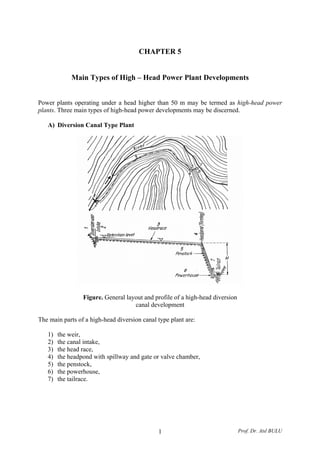
  • 1. CHAPTER 5 Main Types of High – Head Power Plant Developments Power plants operating under a head higher than 50 m may be termed as high-head power plants. Three main types of high-head power developments may be discerned. A) Diversion Canal Type Plant Figure. General layout and profile of a high-head diversion canal development The main parts of a high-head diversion canal type plant are: 1) the weir, 2) the canal intake, 3) the head race, 4) the headpond with spillway and gate or valve chamber, 5) the penstock, 6) the powerhouse, 7) the tailrace. Prof. Dr. Atıl BULU1
  • 2. B) Plants Fed by a Pressure Tunnel Figure. General layout and profile of a pressure tunnel development 1) the dam (sometimes only weir), 2) the intake or headworks, 3) the pressure tunnel, 4) the surge tank, 5) the penstock, 6) the power house, 7) the tailrace. The tunnel intake should be located close to the bottom of the reservoir to ensure the greatest effective storage volume. Under certain topograhic and geologic conditions, the conveyance of water through a tunnel under the dividing range may, even in case of low dams, be preferable to building a long, meandering power canal. Since here the tunnel is not necessarily a pressure conduit, free-surface flow conditions may prevail therein. Such arrangements should be regarded as diversion canal type developments. C) Plants with Concentrated Fall Developments, where the powerhouse is located close to, or within, a high dam or high-head river barrage, constitute the third main type of high-head installations. This arrangement, which could be termed plant with concentrated fall, or valley dam station, is essentially similar to that of low-head run-of-river plants. The head for the power station approaches the height of the dam. Prof. Dr. Atıl BULU2
  • 3. Figure. Development with the powerhouse located at the toe of the dam (plant with concentrated fall) The three main parts of this type of power plants: 1) the water intake (generally built on the upstream face of the dam), 2) the pressure conduit (generally transversing the dam body, sometimes bypassing the dam adjacent rock), 3) the powerhouse. The output of diversion canal developments is closely governed by the discharge available in the river, while the small storage capacity created by the low weir is sufficient to meet daily fluctuations in load only. This type may be called as high-head run-of-river plant. The other two types may be referred to as reservoir plants. Pressure tunnel developments are valuable for those fed from a large reservoir under high head. Free Surface Intakes Settling basins and sand traps are very important for high-head water power plants and they should designed on the basis of hydraulic computations. Suspended load, especially sharp edged fine sand transported by mountain streams causes rapid wear of the penstock and steel parts of the turbines. Water flowing at high velocity and carrying heavy sediment load attacks the lining of power canal and power channels. Scratch effects become generally more pronounced with increasing head, therefore, in case of heads higher than 100 m, sand should be carefully settled out and with heads higher than 200 m even the greatest part of silt fraction should be retained. The main parts of an intake are: 1) the inlet section including the sill and coarse rack, 2) the inlet gate and transition section, 3) the settling basin and sand flushing canal. Prof. Dr. Atıl BULU3
  • 4. Figure. General arrangement of intake Before the inlet section of the intake a bed load deflecting apron should be applied permitting a periodical flushing of bed load hold by the sill. The apron extends to the flushing gate of the weir. Protection against Silting In preventing entrance of bed load, or rather in promoting a desilting effect at the inlet section, in protecting both inlet and canal against sedimentation, the proper choice of intake site is of vital importance. Prof. Dr. Atıl BULU4
  • 5. Changes in the angle of diversion (the angle between the outside wall of the intake structure and the direction of main flow) hardly affect the quantity of sediment entering the canal. More than 90% of transported matter enters the diversion canal branching off at an angle of 300 – 900 from the main course, yet carrying only half of the main discharge. At the same time it can be seen that the angle of diversion has no significant effect upon silting conditions. The curve shown above illustrates the distribution of discharges and silt quantities for a 300 angle of diversion. A balanced (50 – 50 per cent) distribution of silt is attained only if some 25% of the original discharge is allowed to enter the canal. If the discharge carried by the diversion canal exceeds 60%, the entire sediment load enters to the branch canal. Hydrodynamical considerations will yield a very simple explanation for the above phenomenon, that in case of diversion from a straight stretch, the flow entering the power canal carries extremely great quantities of bed load. The velocity component opposite the inlet section and vertical to it, denoted by v, is due to the transverse head loss Δh, the latter given by the equation, hgv Δ= 2μ In one vertical along cross-section (x-x) velocities v due to Δh will be almost uniform. The velocity of direction x-x varies only in direction x within one section and shows an increase from the opposite bank towards the side intake. Since the velocity distribution within the main course above the point of diversion involves a velocity considerably smaller at point B than at the surface, it follows that the deeper the examined subsurface point is situated, the greater the angle formed by the resultant of velocities V and v and by the axis of main flow. Consequently, more water is drawn from deeper layers into the canal than from those nearer to the surface. Thus a lamination according to depth arises in the main flow causing the water entering the power canal to be drawn, for the greater part, from the lower layers that are heavily silted, while water in the upper layers containing considerably less silt overfalls the diversion dam and streams forth in the main course. Prof. Dr. Atıl BULU5
  • 6. Figure. Velocity distribution in the river at the intake The whole bed load is practically is carried into the power canal for big discharges, and the joint application of high sill, silt-sliding apron and sluiceway gives no substantial relief to the problem. Let us examine the bed load conditions of intakes located in a bend. Figure. Profile of the water surface in bends Considering that the water surface as a potential surface normal to the resultant of acting forces, the equation for the sloping water level in the curve may be developed as follows: mg x v m dx dz 2 = Prof. Dr. Atıl BULU6
  • 7. x dx vgdz 2 = Solving the above differential equation, CLnxvgz += 2 Consequently, at point x = R1, z = 0. Thus, 1 2 1 2 R x Ln g v z LnRvC = −= The maximum rise of the surface occurring at the concave bend, 1 2 2 1 2 2 log43.0 2 R R g v R R Ln g v h ××== Velocity of flows shows a tendency to decrease along the same vertical towards the bottom. Particles of water moving in beds at and near the surface are thus subject to greater centrifugal force than those traveling near the bottom. Consequently, particles at and near the surface are forced towards the concave bank. An equal quantity of water is bound to follow at the bottom in the opposite direction towards the convex band due to the principle of continuity. Particles of water submerging with great velocity cause erosion of the bottom along the concave bank. Part and occasionally the whole of eroded matter is then deposited by the flow slowing down towards the convex bank. So the original rectangular cross-section takes and asymmetrical shown as shown in the Figure. Figure. Development of spiral flow in bends Silt of different particle size reaching the bend separates according to size at the peak of the curve. Fine silt settles fairly high on the sand bank formed under water along the convex bank, while coarser grains are carried forth and deposit mostly in or around the holes along the concave bank. It is advisable to have the power canal branch from the concave side in as much as relatively desilted water is required. Prof. Dr. Atıl BULU7
  • 8. Figure. Separation of bed load according to particle size in bends The intake structure is to be built at a point where the spiral flows is strong and the weir is to be located so that the sluiceway or the lateral opening of the movable gate system also falls within the sphere of spiral flow. Figure. Spiral flow at the intake Water discharging into branch does not diverge in a sharp angle but follows a curved route; spiral flow will develop at the upstream end of the canal too, should the diversion be placed either in a straight or in a curved stretch of the water course. Surface flows tend towards the concave side of the curved streamway caused by the diversion, while bottom flow transporting debris is directed towards the canal. With a 50-50 percent ratio of discharges, distribution of bed load is as follows and given in the Figure. 1. Bed load: Canal 100%, main water course 0%, 2. Bed load: Canal 50%, main water course 50%, 3. Bed load: Canal 5%, main water course 95%, 4. Bed load: Canal 100%, main water course 0%, 5. Bed load: Canal 0%, main water course 100%. Prof. Dr. Atıl BULU8
  • 9. Figure. Typical shapes of diversion No. 5 proved most unfavorable as here silt transportation into canal is intensified by synchronizing spiral flows in both original water course and branch canal. No.1 is also highly unfavorable. No. 2, 3, and 5 may be regarded as favorable. No. 2, diversion is at the upstream end of the curve where spiral flow is not yet fully developed and so the effect of flow in the original water course is largely decreased by spiral flow in the branch canal. No 3. and 5 are the most favorable, as here fully developed spiral flow at the downstream end of the bend cannot be considerably lessened by spiral water movements of opposite direction of the branch. The following basic principles governing selection of the intake site can be suggested: 1. Intakes should be located, whenever possible, on the concave side of a curved stretch, 2. Efficiency of the intake in preventing sedimentation increases with the sharpness of the bend, 3. The amount of bed load transported into the canal decreases, as the ratio of the total discharge to the amount increases. 4. Intakes are most favorably located along the downstream reach of the curve, near the end. 5. The lower the head, the more effective the intake. Prof. Dr. Atıl BULU9
  • 10. 6. Conditions in a straight stretch are opposite to those described under No. 3; with diverted flow being constant, any increase in the river discharge will involve more extensive sedimentation in the canal. 7. The silt releasing sluice of the diversion weir, the canal sill and the desilting sluice can only be operated at good efficiency if more or less favorable bend conditions are created through proper design and arrangement in keeping with the above principles. 8. With intakes from straight stretches, but more so along the convex side, the afore- mentioned measures offer no significant contribution to the protection against sedimentation in the canal. In such cases both canal sill and desilting canal give satisfactory results if heads are considerable even during high-head periods. 9. Intakes from straight stretches can be made more favorable by forcing water to follow a curved route with the convex side of stream curve facing the intake structure. Figure. Intakes from straight stretches with bed contraction, a) with flushing (desilting) canal, b) without flushing canal This can be achieved by arrangements illustrated in the above Figure, where an inlet section extending crosswise into rive bed, and a weir shorter than the width of flow above the intake make the flow to follow a curved route. 10. The quantity of bed load can be reduced by a longitudinal baffle wall as shown in the below Figure, if Qd < QB where Qd is the diverted discharge and QB the discharge conveyed in the river in width B of the intake. As a result of inequality Qd < QB part of the water is compelled to deviate on a curved path from the bank, thereby bringing about a silt-diverting spiral flow. B Prof. Dr. Atıl BULU10
  • 11. Protective measures against bed load may be completed by a few remarks. a) The minimum discharge Q0 capable of inducing bed load movement will be decisive of the choice of the site and the arrangement of the intake. The ratio of the plant discharge capacity Qp and of the above limit discharge Q0 is the one of the factors governing the design of intake. b) The individual features of an intake may require the discharge diverted into canal, in certain periods, less than available in the river for power generation. c) Quantitative relations may be established as to the reduction of the discharge diverted. The degree of reduction depends upon the character of the river section. d) Special care should be taken if a power plant having a relatively great discharge capacity is projected on a mountain river. The necessary reduction of the discharge may in this case permit the diversion of a volume corresponding to the maximum plant discharge capacity at times of flood only. e) On mountainous rivers carrying a heavy sediment load, the intake works should always be located on the concave side of the bend even if this side is otherwise less favorable. f) Flow velocity in the inlet section of the intake should preferably be 0.75 m/sec on the average as indicated by experiments conducted between velocity limits of o.50 and 1.10 m/sec. Care should be taken during the hydraulic designing of the settling basin to ensure the calculated velocity in the structure would range 0.40 to 0.60 m/sec. The hydraulic design in settling basins is broadly outlined in the following paragraph. 1) Exploration of sediment conditions, involving the quantitative and qualitative analysis of sediment carried by the river. In mountain rivers or in steep, upper river sections at the average sediment concentration varies from 2 to 10 kg/m3 . 2) Following the investigations of sediment conditions, the necessary degree of load removal, should be determined. Attempts have been made to approximate operating requirements by specifying the diameter of the smallest particles to be settled out (limit particle size). At medium-head plants, the removal of particles larger than 0.2 – 0.5 mm is usually specified. Instead of using the limit particle size, the degree of removal is frequently defined by the removal ratio of concentrations after and before settling expressed in percentages. If the concentration of raw water is C, and that of the clarified water is specified as the permissible value Cp, the required removal ratios is obtained as, C Cp 100 By specifying or assuming the limit particle size, the removal ratio may easily be calculated. 3) Having determined the basic data as suggested, design can be done. First the settling velocity of the smallest fraction; i.e., of the limit particle size to be removed should be calculated theoretically or be established by tests. Prof. Dr. Atıl BULU11
  • 12. The so-called horizontal-flow settling system is usually applied at power developments. For this system, the dimensions of the settling basin may in principal be determined by two computation methods. The effect of turbulent flow upon settling velocity is neglected in the simple settling theory. Three basic relations may be written for the determination of the required basin length. Denoting the depth of the basin by h and its width by b, the discharge passing through basin is, bhVQ = (m3 /sec) Where V is the flow velocity. The second equation expressing the relation between the settling velocity w, the depth of the basin and the settling time t, w h t = (sec) Finally, the length of the basin will be governed by the consideration saying that water particles entering the basin and sediment particles conveyed by them with equal horizontal velocity should only reach the end of the basin after a period longer than the settling time. Thus even the smallest settling particle may strike the bottom of the basin within the settling zone. The retention period should not be shorter than the settling time. The required length of the basin is, Vtl = (m) Eliminating t from the last two relations will be established between the six values governed the hydraulic design: hVlw bhVQ = = A solution of the problem is not possible unless four quantities are known. The discharge Q can always be considered given, the settling velocity w is defined by the initially specified degree of removal and can be established by calculation. The highest permissible flow velocity should also be specified in order to prevent particles once settled from picked up again. The actual flow velocity should not exit this limit, whereas excessive dimensions computed by substantially lower velocities would again result in uneconomical design. Velocities higher than the permissible velocity tend to scour the material settling to the bottom, which may even become suspended again. This limit velocity may in fact be considered equal to the theoretical suspending velocity, or to the critical velocity encountered in the theory of sediment transport. The critical velocity, daV = (cm/sec) Where d is the diameter of particles in mm and the constant a: Prof. Dr. Atıl BULU12
  • 13. a = 36, for d > 1 mm, a = 44, for 1 mm > d > 0.1 mm a = 51 for 0.1 mm> d The fourth dimension that can be assumed in advance is one of the main dimensions of the basin. The depth of the horizontal flow settling basins employed in water power projects is generally between 1.5 and 4.0 m with velocities not higher than from 0.4 to 0.6 m/sec. The water mass conveyed during settling time should equal the capacity of the settling basin. Owing to the retarding effect of turbulent flow on sinking particles, settling is slower in flowing water. By using a lower settling velocity (w – w’), the reduction in settling velocity w’ to be closely related to the flow velocity, aVw =′ (m/sec) The coefficient a may be computed from the relation, h a 132.0 = Where h is the water depth in m. The settling length is therewith, Vh Vh aVw hV l 132.021 23 − = − = (m) A negative denominator is an indication of the fact that no settling can be attained under the assume conditions. The computation should be repeated using the modified dimensions. Prof. Dr. Atıl BULU13
  • 14. The most important factors affecting the design of the settling basin are the quality of sediment (specific weight and shape of particles) density of water carrying sediment and water temperature. All estimates involving the direct application of the afore-mentioned data should be regarded as approximate only. The necessary settling length for turbulent flow is computed from the settling velocity in stagnant water w and from the flow velocity. The settling length, ( ) 2 222 51.7 2.0 w hV l − = λ (m) Where λ depends on the removal ratio defined previously. Values of λ defined by the function, ( )wf=λ W denotes the ratio of settled sediment to the total load entering with the flow and can be computed from the afore-mentioned removal ratio as follow: C C w P 100100−= The settling velocity pertaining to the limit particle size of the fraction to be settled out without assuming 100% removal. Satisfactory values can be obtained by using coefficients pertaining to a 95 to 98% removal of the limit particle size. Prof. Dr. Atıl BULU14
  • 15. Continuous operation can be ensured by one of the following arrangements: a) Series of basins, some of which can be flushed while others operating, b) Permanent operation of basins can also be realized by continuously flushing settled sediment. An inflow exceeding the water demand by 10% should be admitted into the basin and sediment accumulating at the bottom can be flushed continuously by discharging the excess water to waste. Example: Design a settling basin for a high-head power plant by using the settling theory. The basin should serve to remove particles greater than 0.5 mm diameter from the water conveying mainly sand. The design discharge is 5 m3 /sec and assume an initial value of 3.20 m for the depth of the basin. Solution: Determine first the permissible velocity flow velocity. Owing to economical considerations this should equal the critical velocity for which, sec2.315.04444 cmdV === In designing the basin, V = 30 cm/sec flow velocity will be used. The following step is to determine the settling velocity according to the limit particle size of 0.5mm to be removed. From the settling velocity – particle size Figure, w = 6 cm/sec (for γ = 1.064). The required length of the basin is, m w V hl 16 6 30 20.3 =×== And the width, m hV Q b 21.5 3.02.3 5 = × == Checking: The settling time is, sec4.53 06.0 20.3 === w h t The discharge conveyed during this period is, 3 2674.535 mQtV =×== Should be equal to the capacity of the basin; 3 2670.1621.520.3 mhblV =××== Determine the length of the basin using identical basic values by the method of Velikanov’s Figure for a removal ratio of 97% (W=0.97). The Figure yields λ = 1.50 for W = 0.97. The length of the basin is, Prof. Dr. Atıl BULU15
  • 16. ( ) ( ) ml w hV l 19 06.051.7 2.02.33.05.1 51.7 2.0 2 222 2 222 ≅ × −×× = − = λ Example: Compute for the conditions of the preceding example the settling length by considering the retarding effect of turbulent. Solution: The coefficient governing the reduction of settling velocity is, 0737.0 20.3 132.0132.0 === h a And thus the velocity decrement, sec0221.030.00737.0 maVw =×==′ The settling length, m ww hV l 30.25 0221.0060.0 30.020.3 = − × = ′− = The unchanged width of the basin is, m hV Q b 21.5 30.020.3 0.5 = × == And its capacity, 3 42230.2521.520.3 mhblV =××== Example: Compute the modified dimensions for a reduced depth of 2.40 m. Solution: 0851.0 4.2 132.0132.0 === h a m aVw hV l 90.20 30.00851.006.0 30.040.2 = ×− × = − = Width of the basin is, m hV Q b 95.6 30.040.2 5 = × == Prof. Dr. Atıl BULU16
  • 17. And the reduced capacity, 3 3489.2095.640.2 mV =××= Example: A power plant is fed by a river carrying very coarse suspended sediment load. As indicated by the gradation curve obtained for the sediment, 70% are held on the 1 mm screen. In order to protect the turbines the entire over 1 mm diameter should be settled. Solution: %30100 = C Cp The basin will be designed for a discharge of 12 m3 /sec with the retarding effect of turbulent and a depth of 2.80 m will be taken. The critical velocity is, sec4414444 cmdV =×== The settling velocity in stagnant water is obtained from the Figure (for γ = 1.064) W = 10 cm/sec. The settling velocity decrement due to the turbulent, sec0346.044.0 8.2 132.0132.0 mV h W =×==′ The actual settling velocity is, sec0654.00346.0100.0 mWW =−=′− And the settling length, m WW hV l 85.18 0654.0 44.080.2 = × = ′− = The required width of the basin is, m hV Q b 74.9 44.080.2 12 = × == A settling basin 20 m long and 10 m wide will have a capacity of, 3 5608.22010 mV =××= Compute the length of the basin also by the equation of Velikanov (W = 0.97), λ = 1.50, ( ) ml 50.12 10.051.7 2.08.244.050.1 2 222 = × −×× = Prof. Dr. Atıl BULU17
  • 18. Prof. Dr. Atıl BULU18