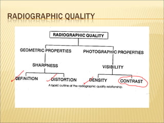
3. Radiographic contrast
The difference in densities between light and dark
The difference in densities between light and dark
regions on the radiograph
regions on the radiograph
The radiographic contrast of an image is the result of the
interplay of subject contrast, film contrast, and scattered
radiation
4.
Radiographic contrast : the differences in
densities .
Such densities variations are called
radiographic contrast.
A radiograph that has marked differences in
densities is a high contrast radiograph.
A radiograph that has less differences in
densities is the a low contrast radiograph.
5.
6.
Is product of two separate factors:
(1) Film contrast, is inherent in the film and is
influenced somewhat by processing of the film.
(2) Subject contrast, is determined by the
size ,shape, and x-ray attenuating
characteristics of the subject being examined
and the energy (kvp) of the x-ray.
7. Patient factors
1. Tissue thickness (age, sex, pathologic change).
2. Tissue opacity (cellular composition, tissue
structure status of organ empty or filled.
3. Tissue densities (gas, fat, muscle, bone)
8. I.
II.
III.
The difference between two adjacent densities
Film displays high or low contrast characteristics
Contrast controls slope of characteristic curve
Optical
Density
Lower
Contrast
log relative exposure
Higher
Contrast
Optical
Density
log relative exposure
9.
Film latitude refers to
the range of exposure
values that will produce
density in accepted
diagnostic range (0.4 2.75).
10. Film Contrast
Film processing: incomplete
or excessive development;
improper storage; light leaks
Film fog: contrast is reduced.
Improper film processing and
storage.
Scattered radiation
Photons that travel in directions other
than that of the primary beam – fogging
of the radiograph
11.
12.
Film with short latitude (high contrast) .Used in
examination of an area of the body with poor
subject contrast, in order to demonstrate
higher radiographic contrast within the
structures being examined.
Film with wide latitude (low contrast). Used in
examination of an area of the body with high
subject contrast, in order to demonstrate
adequate numbers of densities within recorded
image.
13. The useful densities recorded on the film are visible for
comparison as ratio of densities.
The number of useful densities visible on film and the
percentage of difference between them .
Low contrast : (long scale)
the ratio of differences from one adjacent density to an
other is slight (the total number of useful densities would
be maximal).
High contrast : (short scale)
the ratio of differences between densities are considerable
(minimal number of densities ).
14.
15.
(1) Kvp/ mAs relationship.
High contrast: high mAs +low kvp
Low contrast: low mAs +high kvp
(2) Fog levels.
(3) Intensifying screen.
30. High and low mAs effect..
Density is determined principally by mAs
As shown by these radiographs of
abdomen taken at 70 kvp. A,10mAs.
B, plus 25 %, 12.5 mAs C, plus 50 %,
15 mAs.
31.
Scatter radiation negatively affect contrast.
Scatter radiation fog the film(making it Gary)
and reduces the contrast.
The more scatter there is the lower the contrast
You can reduce the amount of scatter radiation
by lowing kvp.
Kvp has to be high enough to penetrate. the
part .
32. Reduce formation of scatter;
1. Used of compression.
2. Beam Restriction devices.
3. Used of low kvp.
Prevent scatter to reach the film;
1. Air gab technique.
2. Used of lead blocker
3. used of x-ray grids.
43.
A device used to reduce
intensity of scatter
radiation in remnant xray beam.
44.
45.
46.
47. • Grid ratios : are the maximum degree of angling before cutoff.
• Grid ratios compares the height of lead strips to the distance between each strip
49. When to use a grid ?
Over 10 cm thickness.
Above 60 kvp
Editor's Notes
ריבוי גווני ביניים – פחות ניגוד
סיבות נפוצות לערפל: חדירת אור לחדר חושך, אחסון לא תקין של הפילם, עודף חשיפה / פיתוח.
מניעת פזור קרינה: מתח נמוך יחסית, collimation, grids בצילום אקסטרא- אורלי.