
Recommended
More Related Content
What's hot
What's hot (20)
Similar to Radiographic grid Swastik
Similar to Radiographic grid Swastik (20)
Recently uploaded
Recently uploaded (20)
Radiographic grid Swastik
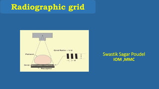
- 1. Radiographic grid Swastik Sagar Poudel IOM ,MMC
- 2. Outline 1. Introduction 2. History 3. Principle 4. Ideal grid 5. Grid construction • Grid ratio • Grid frequency • Grid materials 6. Grid performance 7. Grid types 8. Grid problem 9. Grid selection 10. Patient dose 11. Air gap technique
- 3. Introduction The grid is an extremely effective device for reducing the level of scattered radiation that reaches to the image receptor (IR). A carefully fabricated series of section of radiopaque material (grid stripes) alternating with the section of radiolucent materials (interspace materials). The grid is positioned between the patient and image receptor. The grid is designed to transmit only those x-rays whose direction is on straight line from source to IR. Scattered radiation is absorbed in the grid materials.
- 5. History The grid was first invented in 1913 by Dr Gustav Bucky. Consisted of wide strips of lead approx. 2cm apart in crisscross pattern. Despite the crudeness, it removed enough scatter to improve contrast.
- 6. History In 1920 Dr Hollis Potter, a Chicago radiologist improved Dr Bucky’s grid design. He realigned the lead strips so they would run in only one direction. He made the lead strips thinner and therefore less obvious on the image and design a device (now known as the potter bucky diaphragm) that allowed the grid to move during the exposure. The motion eliminates grid lines.
- 7. Principle When the primary beam interact with the patient’s body, the scattered radiation are produced that may or may not be absorbed depending on angle of incidence and physical characteristics of the grid. If the angle of scattered beam is greater enough to interact lead strips, it is absorbed. If the angle is slight, the scattered beam will be transmitted as the primary beam. Grid removes the scattered radiation before it reaches to the film, therefore it improves contrast.
- 8. Ideal grid Ideal grid; passes all the primary photons i.e. photons coming from focal spot. block all the secondary photons i.e. photons not coming from focal spot
- 9. Grid construction There are three different aspect of grid construction. 1. Grid ratio 2. Grid frequency 3. Grid materials • Interspace materials • Lead strips
- 10. 1:Grid ratio A grid has a three main dimensions 1. the thickness of the grid stripe(T) 2. the width of the interspace materials(D) 3. the height of the grid(h) Grid ratio is the height of grid divided by interspace material thickness. Grid ratio=h/D
- 11. Grid ratio Grid ratio plays a major role in the grid’s ability to improve contrast. Thus, if the height of the grid is constant and the distance between the lead strips is decreased, this will result in an increase in the grid ratio. It determines how scatter radiation is “cleaned up”. Grid ratio is expressed as X:1 Typical values; 5:1 to 16:1 – in general (8:1 to 10:1 generally used) 3:1 to 5:1 _ in mammography (4:1 to 5:1 in mammo) A 5:1 ratio grid will clean up about 85% and 16:1 ratio grid will clean up about 97% of scattered radiation. Higher the grid ratio, the more clean up of scatter radiation. Grid function generally improves with higher ratio.
- 12. 2: Grid frequency It is defined as the number of grid lines per inch or centimeter. Usually ranges from 60-200 lines /inch (25-80lines /cm) Most commonly used grids have frequency of 85-103 lines /inch (33-41 lines/cm) Mammographic grids have frequencies of 80lines /cm (200lines /inch) High frequency grids • More and thinner grid strips • High radiographic technique • Higher patient dose • No significant grid lines on the image
- 13. Digital Imaging Systems Very high-frequency grids • 103-200 lines/in • 41-80 lines/cm
- 14. 3: Grid materials A series of radiopaque lead stripes which alternate with radiolucent materials. a. Strips are held firmly together then sliced into flat sheets. b. Lead is the radiopaque material of choice. 1. Interspace materials • Materials between the grid stripes. • Width varies from 250-350 micron. • It maintains the precise separation between the strips. • Generally constructed from aluminum or plastic fiber.
- 15. Advantages of Aluminum Provides selective filtration of scattered x-ray not absorbed in grid strips. Non- hydroscopic --does not absorb moisture as plastic fibers does. Easy to manufacture as it can be roll into sheets of precise thickness. Produce less visible grid lines on the radiograph.
- 16. Disadvantages 1. Increase the absorption of primary x-ray (low KvP). 2. Higher mAs and higher patient dose. 3. At low KvP, patient radiation dose may be increased by approx;20%. However, Aluminum has definite advantages over plastic fiber. Aluminum is used as the cover for the grid to protect it from damage and moisture. Fiber interspace grids are preferred where their application can contribute to lower patient dose, such as in mammography.
- 17. 2.Grid strips Grid stripes should be thick enough to absorb the scatter radiation and thin enough to allow the primary radiation. The height varies from 2mm-5mm. Lead is widely used material because; • It is easy to shape. • It is relatively inexpensive. • It has high atomic number and high mass density. Tungsten, platinum, gold and uranium can also be used but none of them has overall desirable characteristics that of lead.
- 18. Grid performance The principle function of grid is to improve contrast. There are three methods of evaluating performance; Contrast improvement factor Bucky factor Selectivity
- 19. Contrast Improvement Factor Measures improvement in image quality when grid is used. Grid ratio does not reveal the ability of the grid that how much image contrast is improved than non grid. Contrast improvement factor compares contrast improvement of a radiograph with a grid to that without a grid. It is represented by letter “K”. Contrast improvement factor of 1 indicates no improvement.
- 20. Contrast Improvement Factor Equation K = Radiographic contrast with grid Radiographic contrast without grid Most grids have a contrast improvement of 1.5 - 2.5 Contrast improvement is higher with higher ratio grids K is the complex function of • X ray emission spectrum • Patient thickness • Tissue irradiated
- 21. Bucky Factor Also called grid factor. B=Patient dose with grid Patient dose without grid The higher the grid ratio, the higher is the bucky factor. The amount of radiation hitting the grid will always be greater than the amount hitting the film.
- 22. Grid selectivity Although grids are designed to absorb scatter radiation, they also absorb some primary radiation. Grids that absorb a greater percentage of scatter than primary radiation are described as having a greater degree of selectivity. The better a grid is at removing scatter, the greater will be the selectivity of the grid. This means that a grid with a higher lead content would have a greater selectivity. It is represented by Greek sigma () =Primary radiation transmitted through grid Scatter radiation transmitted through grid
- 23. General Rules Of Grid Characteristics High ratio grids have high contrast improvement factor High frequency grids have thin strips of interspace material Heavy grids have high selectivity and high contrast improvement factors – the heavier a grid is the more lead it contains the higher its selectivity and the more efficient is in cleaning up scatter radiation
- 24. Grid Types 1. Linear Parallel grid Crossed grid 2. Focused grid 3. Moving grid single stroke reciprocating grid oscillating grid
- 25. a) Parallel grid Simplest type of grid . Parallel grids are made with the lead and interspace strips running parallel to one another. This means that if the grid lines were extended into space they would never intersect. More primary radiation cutoff. Not useful for Large area image receptor. Short SID Parallel grids only reduces scatter in the direction of the grid lines. 1:Linear grid
- 26. b) Crossed grid Two linear grids at right angles to each other Used for high contrast studies More efficient in cleanup of scatter radiation than that of parallel grid. Dr Bucky’s original grid was made using this pattern. Higher contrast improvement factor than a parallel grid of twice the grid ratio Restricted application in clinical radiology
- 27. Disadvantages of crossed Grid Grid cut off is the primary disadvantage of a crossed grid. The Central ray must be perfectly aligned with the center of the grid. Tube can not be angled unless x ray tube and table are properly aligned. High exposure technique required
- 28. 2:Focused Grids Designed to minimize grid cut off. Lead strips lie on the imaginary radial lines of a circle centered at the focal spot so they can coincide with the divergence of the x ray beam. If properly positioned ,no grid cutoff. More difficult to manufacture than parallel. Normally the SID is 100cm in table and 180 cm in chest radiography.
- 29. 3) Moving grid Grids lines are visible if primary x rays are absorbed even grid strips are very small Invented by HOLLIS E. POTTER in 1920 with simple idea of moving the while exposure is made Focused grids are usually used Placed in holding mechanism that begins moving just before x-ray exposure and continues moving after end of exposure Moves 1-3 inches Motion blurs out the grid strips
- 30. Single stroke Antiquated /Old fashioned. Grid had to be cocked with a spring mechanism. Worked in correspond with exposure time. The mechanism moved once throughout exposure. Had to be reset for each exposure.
- 31. Reciprocating gird With the reciprocating grid, a motor drives the grid back and forth during the exposure. Does not have to be reset for each exposure. The distance of drive is approx. 2cm.
- 32. Oscillating grid Moves in a circular motion as opposed to back and forth. Delicate , Spring like devices located in the four corners hold the grid centered within the frame. A powerful electromagnet pulls the grid to one side and releases it at the beginning of the exposure. The grid oscillates in a circular fashion around the grid frame, coming to rest after 20-30 secs.
- 33. Advantages of moving grid. • No grid lines are seen. • Problems occur infrequently. • Motion blur is undetectable. Disadvantages • Mechanical problems may occur. • Costly. • Increase the patient radiation dose. • Very infrequently, the motion is detected in the radiograph
- 34. Mammographic grid Moving grid with ratio of 4:1 to 5:1. Grid frequencies of 30-40 lines /cm. Bucky factor:2-3 Does not compromise spatial resolution but increases pt. dose. 4:1 ratio grid doubles the pt. dose compared to non grid contact mammography. HTC grid is the choice.
- 35. High transmission cellular grid (HTC) Reduces scatter radiation in the two directions. Grid strips are made up of copper. Interspace material is air. Physical dimensions-3.8:1
- 36. Grid problems Most frequent error – improper positioning For correct functioning, precisely positioned in relative to the x ray tube target and central ray of the x ray beam Problems associated with focused grid 1. off-level 2. off- center 3. off- focus 4. upside down 5. off-center ,off-focus
- 37. 1. Off level This occurs when the central ray is angled across the long axis of the grid strips/ across the radiographic table. Improper positioned x-ray tube not the grid May occur during the grid tilting during horizontal beam or in mobile radiography. Central rays incident on the grid at angle. Grid cutoff will occur.
- 38. 2. Off center If the central ray is not properly centered to the centermost interspace of the grid i.e. lateral shifting of grid Common problem with mobile x-ray tables or ceiling suspended tubes. Arises due to improper tube position Also called lateral decentering
- 39. 3. Off focused Unspecified SIDs selection in case of the focused grid Major problem with high ratio grids. Grid cutoff occurs if distance increases Grid cut off more severe at the edge than the center This problem will not be observed if all chest radiograph are taken at 180cm SID and all table radiographs at 100cm SID.
- 40. 4. Upside down Major grid problem but will be noticed easily. Maximum cutoff on either side of central ray. This type of grid error occurs when the radiographic grid is used upside-down. It is important that the technologist check the tube side prior to using a focusing grid.
- 41. 5. Combined off center and off focused Most common improper grid position. Mostly occurs during mobile radiography. Resultant radiograph with dark on one side and light on the other i. e. uneven exposure. Can be easily recognized.
- 42. Grid selection Do not use the grid for children Grid can be used if thickness is >10cm Moving grid is the best than stationary grid Moving grid with focused grid strips is common than parallel one Up to 8:1 ratio is good for <90KVp used and more than 8:1 is good for >90KVp Choice of grid is also depends on the size and shape of anatomy that is being examined 4:1 or 5:1 ratio with 30-40 lines/cm is good for mammography But the HTC grid is the choice for mammography.
- 43. Grid selection factor Patient dose increases with increasing grid ratio. High ratio grids are used for high kVp examinations. Patient dose at high kVp is less than that at low kVp.
- 44. Patient dose Moving grid increases pt. dose by 15% than the stationary The use of high KVp and high- ratio grids results in lower patient doses and equal image quality than the use of low-KVp and low-ratio grid Disadvantages of using grid • Increase patient dose • Increased radiographic technique required (Usually mAs than kVp)
- 45. Contd; Grid ratio mAs increase kVp increase • No grid 1X 0 • 5:1 2X +8 to 10 • 8:1 4X +13 to 15 • 12:1 6X + 20 to 25 • 16:1 8X + 30 to 40
- 46. Problem; • Original: 20mAs with an 8:1 grid then, Find new mAs with a 12:1 grid mAs2 = 20 mAs x 6 4 mAs2 = 120 4 mAs2 = 30
- 47. Air gap technique The air gap technique is an alternative to use of a grid. It has primary application in magnification radiography to a lesser extent , in chest radiography and c-spine lateral radiograph. The technique involves placing the patient at a greater object image receptor distance (OID). Image receptor is moved 10 to 15cm from the patient. By moving patient away from the image receptor, the amount of scatter reaching the image receptor will be reduced.
- 48. Contd; The result is improved contrast without the use of grid. mAs usually increased approx. 10% for every centimeter of air gap. The primary disadvantage of air gap technique is the loss of sharpness that results from increased OID.
- 49. References Radiologic Science for Technologist (Physics, Biology and Protection) by Stewart C. Bushong, 9th Edition. Chesney equipment Website articles
- 50. THANK YOU
Editor's Notes
- Usually patient dose at high KVp with low mAs is less than at low kvp with high mas.