Vector Search -An Introduction in Oracle Database 23ai.pptx
Chapter 18 1
1. Chapter 18: Planar Kinetics of a Rigid Body: Work and Energy
CHAPTER OBJECTIVES
To develop formulations for the kinetic energy of a body, and define the various ways a force
and couple do work.
To apply the principle of work and energy to solve rigid-body planar kinetic problems that involve
force, velocity, and displacement.
To show how the conservation of energy can be used to solve rigid-body planar kinetic
problems.
18.1 Kinetic Energy
In this chapter we will apply work and energy methods to problems involving force, velocity, and displacement
related to the planar motion of a rigid body. Before doing this, however, it will first be necessary to develop a
means of obtaining the body's kinetic energy when the body is subjected to translation, rotation about a fixed
axis, or general plane motion.
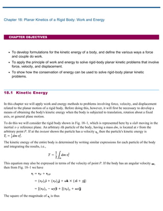
To do this we will consider the rigid body shown in Fig. 18–1, which is represented here by a slab moving in the
inertial x–y reference plane. An arbitrary ith particle of the body, having a mass dm, is located at r from the
arbitrary point P. If at the instant shown the particle has a velocity then the particle's kinetic energy is
The kinetic energy of the entire body is determined by writing similar expressions for each particle of the body
and integrating the results, i.e.,
This equation may also be expressed in terms of the velocity of point P. If the body has an angular velocity
then from Fig. 18–1 we have
The square of the magnitude of is thus
2. Substituting into the equation of kinetic energy yields
The first integral on the right represents the entire mass m of the body. Since and
the second and third integrals locate the body's center of mass G with respect to P. The last integral represents
the body's moment of inertia computed about the z axis passing through point P. Thus,
(18–1)
As a special case, if point P coincides with the mass center G for the body, then and therefore
(18–2)
Here is the moment of inertia for the body about an axis which is perpendicular to the plane of motion and
passes through the mass center. Both terms on the right side are always positive, since the velocities are squared.
Furthermore, it may be verified that these terms have units of length times force, common units being or
Recall, however, that in the SI system the unit of energy is the joule (J), where
Fig. 18–1
Translation
When a rigid body of mass m is subjected to either rectilinear or curvilinear translation, the kinetic energy due to
rotation is zero, since From Eq. 18–2, the kinetic energy of the body is therefore
(18–3)
where is the magnitude of the translational velocity v at the instant considered, Fig. 18–2.
3. Fig. 18–2
Rotation About a Fixed Axis
When a rigid body is rotating about a fixed axis passing through point O, Fig. 18–3, the body has both
translational and rotational kinetic energy as defined by Eq. 18–2, i.e.,
(18–4)
Fig. 18–3
The body's kinetic energy may also be formulated by noting that in which case By
the parallel-axis theorem, the terms inside the parentheses represent the moment of inertia of the body about
an axis perpendicular to the plane of motion and passing through point O. Hence,
(18–5)
From the derivation, this equation will give the same result as Eq. 18–4, since it accounts for both the
translational and rotational kinetic energies of the body.
General Plane Motion
When a rigid body is subjected to general plane motion, Fig. 18–4, it has an angular velocity and its mass
center has a velocity Hence, the kinetic energy is defined by Eq. 18–2, i.e.,
(18–6)
Here it is seen that the total kinetic energy of the body consists of the scalar sum of the body's translational
kinetic energy, and rotational kinetic energy about its mass center,
4. Fig. 18–4
Because energy is a scalar quantity, the total kinetic energy for a system of connected rigid bodies is the sum of
the kinetic energies of all its moving parts. Depending on the type of motion, the kinetic energy of each body is
found by applying Eq. 18–2 or the alternative forms mentioned above.
The total kinetic energy of this soil compactor consists of the kinetic energy of the body or frame of the
machine due to its translation, and the translational and rotational kinetic energies of the roller and the wheels
due to their general plane motion. Here we exclude the additional kinetic energy developed by the moving
parts of the engine and drive train.
E X A M P L E 18.1
The system of three elements shown in Fig. 18–5a consists of a 6-kg block B,
a 10-kg disk D, and a 12-kg cylinder C. If no slipping occurs, determine the
total kinetic energy of the system at the instant shown.
Fig. 18–5a
Solution
In order to compute the kinetic energy of the disk and cylinder, it is first
necessary to determine and Fig. 18–5a. From the kinematics of the
disk,
5. Since the cylinder rolls without slipping, the instantaneous center of zero
velocity is at the point of contact with the ground, Fig. 18–5b, hence,
Fig. 18–5b
Block
Disk
Cylinder
The total kinetic energy of the system is therefore
Ans.
6. Chapter 18: Planar Kinetics of a Rigid Body: Work and Energy
18.2 The Work of a Force
Several types of forces are often encountered in planar kinetics problems involving a rigid body. The work of
each of these forces has been presented in Sec. 14.1 and is listed below as a summary.
Work of a Variable Force
If an external force F acts on a rigid body, the work done by the force when it moves along the path s, Fig. 18–6,
is defined as
(18–7)
Here is the angle between the “tails” of the force vector and the differential displacement. In general, the
integration must account for the variation of the force's direction and magnitude.
Fig. 18–6
Work of a Constant Force
If an external force acts on a rigid body, Fig. 18–7, and maintains a constant magnitude and constant
direction while the body undergoes a translation s, Eq. 18–7 can be integrated so that the work becomes
(18–8)
Here represents the magnitude of the component of force in the direction of displacement.
7. Fig. 18–7
Work of a Weight
The weight of a body does work only when the body's center of mass G undergoes a vertical displacement If
this displacement is upward, Fig. 18–8, the work is negative, since the weight and displacement are in opposite
directions.
(18–9)
Likewise, if the displacement is downward the work becomes positive. In both cases the elevation change
is considered to be small so that W, which is caused by gravitation, is constant.
Fig. 18–8
Work of a Spring Force
If a linear elastic spring is attached to a body, the spring force acting on the body does work when the
spring either stretches or compresses from to a further position In both cases the work will be negative
since the displacement of the body is in the opposite direction to the force, Fig. 18–9. The work done is
(18–10)
where
Fig. 18–9
Forces That Do No Work
There are some external forces that do no work when the body is displaced. These forces can act either at fixed
points on the body, or they can have a direction perpendicular to their displacement. Examples include the
8. reactions at a pin support about which a body rotates, the normal reaction acting on a body that moves along a
fixed surface, and the weight of a body when the center of gravity of the body moves in a horizontal plane, Fig.
18–10. A rolling resistance force acting on a round body as it rolls without slipping over a rough surface also
does no work, Fig. 18–10. This is because, during any instant of time dt, acts at a point on the body which has
zero velocity (instantaneous center, IC), and so the work done by the force on the point is zero. In other words,
the point is not displaced in the direction of the force during this instant. Since contacts successive points for
only an instant, the work of will be zero.
Fig. 18–10
9. Chapter 18: Planar Kinetics of a Rigid Body: Work and Energy
18.3 The Work of a Couple
When a body subjected to a couple undergoes general plane motion, the two couple forces do work only when
the body undergoes a rotation. To show this, consider the body in Fig. 18–11a, which is subjected to a couple
moment Any general differential displacement of the body can be considered as a translation plus
rotation. When the body translates, such that the component of displacement along the line of action of the forces
is Fig. 18–11b, clearly the “positive” work of one force cancels the “negative” work of the other. If the body
undergoes a differential rotation about an axis which is perpendicular to the plane of the couple and intersects
the plane at point O, Fig. 18–11c, then each force undergoes a displacement in the direction of the
force. Hence, the total work done is
Here the line of action of is parallel to the line of action of M. This is always the case for general plane
motion, since M and are perpendicular to the plane of motion. Furthermore, the resultant work is positive
when M and have the same sense of direction and negative if these vectors have an opposite sense of
direction.
Fig. 18–11
10. When the body rotates in the plane through a finite angle measured in radians, from to the work of a
couple is
(18–11)
If the couple moment M has a constant magnitude, then
(18–12)
Here the work is positive provided M and are in the same direction.
E X A M P L E 18.2
The bar shown in Fig. 18–12a has a mass of 10 kg and is subjected to a couple
moment of and a force of which is always applied
perpendicular to the end of the bar. Also, the spring has an unstretched length
of 0.5 m and remains in the vertical position due to the roller guide at B.
Determine the total work done by all the forces acting on the bar when it has
rotated downward from ¡ to ¡.
Fig. 18–12a
Solution
First the free-body diagram of the bar is drawn in order to account for all the
forces that act on it, Fig. 18–12b.
Fig. 18–12b
Weight W. Since the weight is displaced downward 1.5
11. m, the work is
Why is the work positive?
Couple Moment M. The couple moment rotates through an angle of
Hence
Spring Force When ¡ the spring is stretched and when
¡, the stretch is Thus
By inspection the spring does negative work on the bar since acts in the
opposite direction to displacement. This checks with the result.
Force P. As the bar moves downward, the force is displaced through a
distance of The work is positive. Why?
Pin Reactions. Forces and do no work since they are not displaced.
Total Work. The work of all the forces when the bar is displaced is thus
Ans.