DME-1 18ME52 QP for Examination Preparation
•
0 likes•774 views

Design of Machine Elements -1 18ME52 as per the VTU syllabus 66 questions for Examination Preparation

Recommended
More Related Content
What's hot
What's hot (20)
Similar to DME-1 18ME52 QP for Examination Preparation
Similar to DME-1 18ME52 QP for Examination Preparation (20)
More from Mohammed Imran
More from Mohammed Imran (20)
Recently uploaded
Recently uploaded (20)
DME-1 18ME52 QP for Examination Preparation
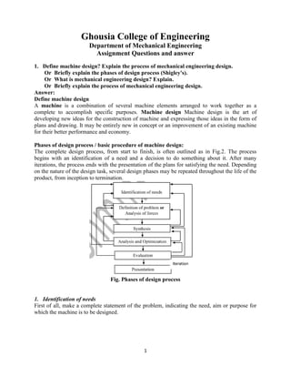
- 1. 1 Ghousia College of Engineering Department of Mechanical Engineering Assignment Questions and answer 1. Define machine design? Explain the process of mechanical engineering design. Or Briefly explain the phases of design process (Shigley's). Or What is mechanical engineering design? Explain. Or Briefly explain the process of mechanical engineering design. Answer: Define machine design A machine is a combination of several machine elements arranged to work together as a complete to accomplish specific purposes. Machine design Machine design is the art of developing new ideas for the construction of machine and expressing those ideas in the form of plans and drawing. It may be entirely new in concept or an improvement of an existing machine for their better performance and economy. Phases of design process / basic procedure of machine design: The complete design process, from start to finish, is often outlined as in Fig.2. The process begins with an identification of a need and a decision to do something about it. After many iterations, the process ends with the presentation of the plans for satisfying the need. Depending on the nature of the design task, several design phases may be repeated throughout the life of the product, from inception to termination. Fig. Phases of design process 1. Identification of needs First of all, make a complete statement of the problem, indicating the need, aim or purpose for which the machine is to be designed.
- 2. 2 2. Definition of problem The definition of problem is more specific and must include all the specifications for the object that is to be designed. The specifications are the input and output quantities, the characteristics and dimensions of the space the object must occupy, and all the limitations on these quantities. 3. Synthesis It is a process to select the possible mechanism or group of mechanisms which will give the desired motion. 4. Analysis and Optimization The optimization is a called altering, modification and redesigning the size of the existing machines in an innovative ideal design of machine which may have best performance, efficiency and low cost. The analysis of selected machine mechanism carried out by the analysis of forces, material selection and design of elements (size and stresses). 5. Evaluation Evaluation is a significant phase of the total design process. Evaluation is the final proof of a successful design and usually involves the testing of a prototype in the laboratory. Here we wish to discover if the design really satisfies the needs. 6. Presentation The engineer, when presenting a new solution to administrative, management, or supervisory persons, is attempting to sell or to prove to them that their solution is a better one. Unless this can be done successfully, the time and effort spent on obtaining the solution have been largely wasted. 2. What are the basic requirements of machine elements? Explain briefly. Or Briefly discuss the factors influencing the selection of suitable material for machine elements Or Explain material selection in mechanical engineering design. Answer: The strength required of an element in a system is an important factor in the determination of the geometry and the dimensions of the element. Some of the important basic parameters or factors are influencing the selection of suitable material for machine elements such as follows. (1) High Strength, (2) High Hardness, (3) Higher Toughness, (4) Good Malleability, (5) Higher Ductility, (6) Good Thermal Properties, (7) Good corrosion resistance, (8) Good wear resistance, (9) Minimum life cycle cost (10) Good Machine-ability (11) Availability, (12) Weld-ability . 3. Explain engineering materials and their mechanical properties. Or What are the important mechanical properties of the metal and explain each of them briefly. Answer: Engineering Materials: The engineering materials are metals and their alloys, such as iron, steel, copper, aluminum, etc. and non metals such as glass, rubber, plastic, etc. which has vast application in machines and other. The flow chart shows the common engineering materials as follows.
- 3. 3 Fig.3. Mechanical properties of Engineering Materials: Physical Properties of Metals The physical properties of the metals include luster, colour, size and shape, density, electric and thermal conductivity, and melting point. Mechanical Properties of Metals The mechanical properties of the metals are those which are associated with the ability of the material to resist mechanical forces and load. These mechanical properties of the metal include strength, stiffness, elasticity, plasticity, ductility, brittleness, malleability, toughness, resilience, creep and hardness. We shall now discuss these properties as follows: Fig.4. a. Strength. It is the ability of a material to resist the externally applied forces without breaking or yielding. The internal resistance offered by a part to an externally applied force is called stress. b. Stiffness. It is the ability of a material to resist deformation under stress. The modulus of elasticity is the measure of stiffness. c. Elasticity. It is the property of a material to regain its original shape after deformation when the external forces are removed shown in fig.4.(a) point E. This property is desirable for materials used in tools and machines. It may be noted that steel is
- 4. 4 more elastic than rubber d. Plasticity. It is property of a material which retains the deformation produced under load permanently shown in fig.4.(a) point U. This property of the material is necessary for forgings, in stamping images on coins and in ornamental work. e. Ductility. It is the property of a material enabling it to be drawn into wire with the application of a tensile force. A ductile material must be both strong and plastic. The ductility is usually measured by the terms, percentage elongation and percentage reduction in area. The ductile material commonly used in engineering practice (in order of diminishing ductility) are mild steel, copper, aluminium, nickel, zinc, tin and lead. f. Brittleness. It is the property of a material opposite to ductility. It is the property of breaking of a material with little permanent distortion. Brittle materials when subjected to tensile loads snap off without giving any sensible elongation. Cast iron is a brittle material. g. Malleability. It is a special case of ductility which permits materials to be rolled or hammered into thin sheets. A malleable material should be plastic but it is not essential to be so strong. The malleable materials commonly used in engineering practice (in order of diminishing malleability) are lead, soft steel, wrought iron, copper and aluminium. h. Toughness. It is the property of a material to resist fracture due to high impact loads like hammer blows. The toughness of the material decreases when it is heated. It is measured by the amount of energy that a unit volume of the material has absorbed after being stressed upto the point of fracture. This property is desirable in parts subjected to shock and impact loads shown in fig.4.(b). i. Machinability. It is the property of a material which refers to a relative case with which a material can be cut. The machinability of a material can be measured in a number of ways such as comparing the tool life for cutting different materials or thrust required to remove the material at some given rate or the energy required to remove a unit volume of the material. It may be noted that brass can be easily machined than steel. j. Resilience. It is the property of a material to absorb energy and to resist shock and impact loads. It is measured by the amount of energy absorbed per unit volume within elastic limit. This property is essential for spring materials. shown in figure.4.(a) k. Creep. When a part is subjected to a constant stress at high temperature for a long period of time, it will undergo a slow and permanent deformation called creep. This property is considered in designing internal combustion engines, boilers and turbines. l. Fatigue. When a material is subjected to repeated stresses, it fails at stresses below the yield point stresses. Such type of failure of a material is known as *fatigue. The failure is caused by means of a progressive crack formation which are usually fine and of microscopic size. This property is considered in designing shafts, connecting rods, springs, gears, etc. m. Hardness. It is a very important property of the metals and has a wide variety of meanings. It embraces many different properties such as resistance to wear, scratching, deformation and machinability etc. It also means the ability of a metal to cut another metal. The hardness is usually expressed in numbers which are dependent on the method of making the test. The hardness of a metal may be determined by the following tests: a. Brinell hardness test, b. Rockwell hardness test, c. Vickers hardness (also called Diamond Pyramid) test, and d. Shore scleroscope.
- 5. 5 4. Explain the importance of standards in design & list different standards used. Answer: A standard is a set of specifications for parts, materials, or processes intended (anticipated) to achieve uniformity, efficiency, and a specified quality as defined by a certain body or an organization. One of the important purposes of a standard is to limit the multitude of variations that can arise from the arbitrary creation of a part, material, or process (Characteristics are include the dimensions, shapes, tolerances, surface finish, manufacturing methods etc.). List of standards 1 American Society of Mechanical Engineers (ASME) 2 American Society of Testing and Materials (ASTM) 3 American standards for materials ASM 4 International Standards Organization (ISO) 5 Aluminum Association (AA) 5. Define standards and codes Answer: A standard is a set of specifications for parts, materials, or processes intended (anticipated) to achieve uniformity, efficiency, and a specified quality as defined by a certain body or an organization. A code is a set of specifications for the analysis, design, manufacture, and construction of something. The purpose of a code is to achieve a specified degree of safety, efficiency, and performance or quality. 6. Discuss the factors influencing selection of appropriate value of the factor of safety. Or Define factor of safety and explain factors influencing to it for selection of machine elements Or Explain the factor of safety and factors influencing to it. Answer: While designing a component, it is necessary to provide sufficient reserve strength in case of an accident. This is achieved by taking a suitable factor of safety (F.O.S). The factor of safety is defined as the ratio of the maximum or failure stress to the working or allowable stress. 𝐹. 𝑂. 𝑆 = 𝑀𝑎𝑥𝑖𝑚𝑢𝑚 𝑜𝑟 𝐹𝑎𝑖𝑙𝑢𝑟𝑒 𝑠𝑡𝑟𝑒𝑠𝑠 𝑤𝑜𝑟𝑘𝑖𝑛𝑔 𝑜𝑟 𝑎𝑙𝑙𝑜𝑤𝑎𝑏𝑙𝑒 𝑠𝑡𝑟𝑒𝑠𝑠 = 𝐹𝑎𝑖𝑙𝑢𝑟𝑒 𝑙𝑜𝑎𝑑 𝑤𝑜𝑟𝑘𝑖𝑛𝑔 𝑙𝑜𝑎𝑑 The allowable stress is the stress value, which is used in design to determine the dimensions of the component. It is considered as a stress, which the designer expects will not be exceeded under normal operating conditions. For ductile materials, the allowable stress is obtained by the following relationship: = 𝑌𝑖𝑒𝑙𝑑 𝑠𝑡𝑟𝑒𝑠𝑠 (𝜎 ) 𝐹. 𝑂. 𝑆 For brittle materials, the relationship is, = 𝑈𝑙𝑡𝑖𝑚𝑎𝑡𝑒 𝑠𝑡𝑟𝑒𝑠𝑠 (𝜎 ) 𝐹. 𝑂. 𝑆
- 6. 6 There are a number of factors which are difficult to evaluate accurately in design analysis. Some of the factors influencing are as follows: a. Uncertainty in the magnitude of external force acting on the component. b. Variations in the properties of materials like yield strength, ultimate strength corrosion, or creep. c. Variations in the dimensions of the component due to imperfect workmanship. d. In-homogeneity of materials. e. Residual stresses due to different manufacturing process. f. Fluctuating load (fatigue loading): Experimental results and plot- ultimate strength depends on number of cycles. g. Safety and reliability. 7. Explain stress concentration and methods are used to reducing stress concentration. Answer: Stress concentration is defined as the localization of high stresses due to the irregularities present in the component and abrupt changes of the crosssection. The cause of this highly localized or accumulation of stress is termed as stress raiser. The principal cause of stress raisers due to some discontinuities are present in machine components. Method of reducing stress concentration of Mitigation of stress concentration Although it is not possible to completely eliminate the effect of stress concentration, there are methods to reduce stress concentrations. This is achieved by providing a specific geometric shape to the component. The following methods used for the minimization of stress concentration. 1. Drilling additional holes Consider the plate having centrally hole with axial loading shown in figure 1.(a) the maximum stress get accumulated at the change of cross-section near the hole and it is bad design. This accumulation of stress reduced to some extent by drilling to more additional small holes shows in fig.1.(b) such that the flow of line become more uniform and better design. Fig.1.(a). Bad design Fig.1.(b). Preferred design 2. Using fillets instead of shoulders Consider a plate having a shoulder (sharp corner) is loaded axially shown in fig.2(b), the stress gets accumulated near the shoulder and leads to stress concentration, hence a bad design. This can be reduced by providing fillets (round corners) instead of sharp shoulders as shown in fig.2.(b)
- 7. 7 Fig.2.(a). Bad design Fig.2.(b). Preferred design 3. Use of multi notches Consider a U notched plate and axially loaded shown in fig.3(a). The maximum stress accumulated near the notch the change due to change in cross-section and hence a bad design. In fig.3.(b) shows providing additional notches, the crowding force flow line near to the U notch can be reduced resulting in a better design. Fig.3.(a). Bad design Fig.3.(b). Preferred design 4. using larger diameter of threaded length Fig.4.(a). Bad design Fig.4.(b). Preferred design A threaded component is shown in Fig. 4 (a). It is observed that the force flow line is bent as it passes from the shank portion to threaded portion of the component. This results in stress concentration in the transition plane. An ideal method to reduce stress concentration is illustrated in Fig.4(b), where the shank diameter is reduced and made equal to the core diameter of the thread. In this case, the force flow line is almost straight and there is no stress concentration. 5. Removal of unwanted materials Fig.5.(a). Bad design Fig.5.(b). Preferred design 8. Define stress concentration and explain factors influencing. Answer: Stress concentration is defined as the localization of high stresses due to the irregularities present in the component and abrupt changes of the crosssection. The cause of this highly localized or accumulation of stress is termed as stress raiser. The principal cause of stress raisers due to some discontinuities are present in machine components. Factors influencing for stress concentration (1) Variation in Properties of Materials. (2) Load Application (3) Abrupt Changes in Section (4) Discontinuities in the Component (5) Machining Scratches Machining
- 8. 8 9. A beam of uniform rectangular C/S of fixed at one end and carries a load 1000N at a distance of 300mm from the fixed end. The maximum bending stress in the beam is 80 N/mm2 . Find the width and depth of beam. If depth is twice of width. 10. A circular rod of diameter 50mm is subjected to loads as shown in fig. Q (10). Determine the nature and magnitude of stresses at the critical points. Fig. Q(10) 11. A 50mm diameter steel rod supports a 9.0kN load and in addition is subjected to a torsional moment of 100N-m as shown in fig. Q(11). Determine the maximum tensile and the maximum shear stress. Fig. Q(11) 12. Determine extreme fiber stress at section x-x of the machine member loaded as shown in fig.Q(12). Also show the distribution of stresses at this section. All dimensions are in mm. Fig. Q(12) 13. A wall bracket with rectangular cross section is shown in fig.Q(13). The force P acting on the bracket at 600 to the vertical is 5kN. The material of the bracket is gray cast iron (ordinary) and factor of safety is 2. Determine the cross section of the bracket for the maximum normal stress. All dimensions are in mm.
- 9. 9 Fig. Q(13) 14. An Overhang crank with pin and shaft is as shown in fig. Q(14) a tangential load 15kN acts on the crank pin. Determine the diameter at section X-X using maximum shear stress theory. The crank is made of C60 carbon steel. Take factor of safety as 2. All dimensions are in mm. F ig.Q.(14) 15. Determine the maximum normal stress and maximum shear stress at section A-A for the crank hown in fig. Q(15) when a load of 10kN is assumed to concentrated at the centre of crank pin. (15) 16. Determine the maximum stress in the following cases taking stress concentration into account.
- 10. 10 a. A Rectangular plate of 50mm x 80mm with a hole of 10mm diameter in the center is loaded in axial tension of 10kN. Thickness of the plate is 10mm. b. A circular shaft of 45mm diameter stepped down to 30mm diameter having fillet radius of 6mm subjected to a twisting moment of 15Nm. (VTU, July/Aug. 2003, June/July 2013) 17. A round shaft of 50mm diameter is subjected to a bending moment of 100Nm. If A transverse circular hole of 10mm diameter is drilled on the shaft, determine the maximum stress induced on the shaft. 18. A rectangular plate of 50mm wide with a circular hole of diameter 10mm in the centre is subjected to a bending moment of 10 Nm. If the thickness of the plate is 10mm, determine the maximum stress induced in the plate. 19. A rectangular plate 15mm thick made of a brittle material ia shown in fig Q(19), Calculate stresses at each of three holes. Fig Q(19) 20. A flat bar shown in fig Q(20), is subjected to axial load of 100kN. Assuming that the stress in the bar is limited to 200 N/m2 , Determine the thickness of bar. Fig. Q(20) 21. A stepped shaft shows in fig Q(21), is subjected to a transverse load. The shaft is made of steel with ultimate tensile strength of 400 Mpa. Determine the diameter d of the shaft based on the factor of safety of 2. Fig Q(21),
- 11. 11 22. A flat plate subjected to a tensile force of 5kN is shown in fig Q(14). The plate material is grey cast iron good. Determine the thickness of the plate. Factor of safety is 2.5. Fig. Q(22) 23. Determine the safe load that can be carried by a bar of rectangular C/S in fig. Q(23) limiting the maximum stress to 130 MPa taking stress concentration into account. Fig. Q(23).
- 12. 12 24. Drive the instantaneous stress due to axial impact. Or Drive an expression for stress induced in a rod to the axial impact of weight W dropped from a height of h on a collar attached at the free end of the rod. What the stress due to suddenly applied load. Answer: Consider an elastic system loaded by a falling weight W as shown in fig.1. investigate the effect of impact due to axial loads. Impact axial loads [Derivation of instantaneous stress due to axial impact] The stress produced in the member due to the falling load is known as impact stress. Consider a load W is dropped from a height h on the end of a vertical bar shows in figure 1 which produces instantaneous deformation e' or max and , 1, i or max stress Let A be the Cross sectional area of bar. E is Young's modulus. l is Length of bar. e' deformation of the bar due to the impact. , 1, i or max is stress induced in the bar due to impact. h height through which the load Falls or Height of fall. P force at which the deformation e' is produced. e static deformation due to weight W. W weight of the falling body. Fig. 1. The work done by the falling body is equal to its change in potential energy. Work done = W (h + e') or W (h + max) Since the energy gained by the system is equal to the potential energy lost by the weight 1 2 𝑃𝑒 = 𝑊 (ℎ + 𝑒 ) 𝑤ℎ𝑒𝑟𝑒 𝑃 = 𝜎 . 𝐴 𝑎𝑛𝑑 𝑒 = 𝜎 × 𝑙 𝐸 − − − (𝑖) Substituting this values in equation (i) we get 1 2 (𝜎 . 𝐴) × 𝜎 × 𝑙 𝐸 = 𝑊 ℎ + 𝜎 × 𝑙 𝐸 , 𝑙𝐴 2𝐸 = ℎ𝑊 + 𝜎 𝑙𝑊 𝐸 𝑙𝐴 2𝐸 𝜎, − 𝑙𝑊 𝐸 𝜎 − ℎ𝑊 = 0 W.K.T 𝑥 + 𝑎𝑥 + 𝑏 = 0 𝑥 = −𝑏 ± √𝑏 − 4𝑎𝑐 2𝑎 The above equation is a quadratic equation. Solving the equation and using positive sign for getting maximum value, , = − − 𝑙𝑊 𝐸 ± − 𝑙𝑊 𝐸 − 4 𝑙𝐴 2𝐸 (−ℎ𝑊) 2 𝑙𝐴 2𝐸 , = 𝑙𝑊 𝐸 ± 𝑙𝑊 𝐸 + 2 𝑙𝐴 𝐸 (ℎ𝑊) 𝑙𝐴 𝐸 = 𝑙𝑊 𝐸 ± 𝑙𝑊 𝐸 1 + 2 𝑙𝐴 𝐸 𝐸 𝑙𝑊 (ℎ𝑊) 𝑙𝐴 𝐸
- 13. 13 , = 𝑙 𝐸 1 𝑙𝐴 𝐸 𝑊 ± 𝑊 1 + 2 𝐴ℎ𝐸 𝑙𝑊 = 1 𝐴 𝑊 ± 𝑊 1 + 2 𝐴ℎ𝐸 𝑙𝑊 , = 𝑊 𝐴 1 ± 1 + 2 ℎ𝐴𝐸 𝑊𝑙 − − − −(7) Equation (7) is in D.D.H.B Eq (3-12) page 49 Considering positive sign Impact stress , = 𝜎 = 𝜎 = 1 + 1 + 2 or , = 𝜎 = 𝜎 = 𝜎 1 + 1 + 2 Now multiplying both side of equation (7) by the equation becomes , × 𝑙 𝐸 = 𝑊 𝐴 × 𝑙 𝐸 1 ± 1 + 2 ℎ𝐴𝐸 𝑊𝑙 W.K.T 𝑊𝑙 𝐴𝐸 = 𝛿 = 𝑠𝑡𝑎𝑡𝑖𝑐 𝑑𝑒𝑓𝑜𝑟𝑚𝑎𝑡𝑖𝑜𝑛 = 𝑒 = 𝛿 1 ± 1 + 2 ℎ 𝛿 = 𝑒 1 ± 1 + 2 ℎ 𝑒 − − − (8) Equation (8) is in D.D.H.B Eq (3-13) page 49. The quantity 1 ± 1 + 2 is called the impact factor because it converts the effect of a falling weight to an equivalent static force. 25. Drive the instantaneous stress due to bending impact. Answer: Consider an elastic system loaded by a falling weight W as shown in fig.1. and also investigate the effect of impact due to axial and bending loads. Impact bending loads (Derivation of instantaneous stress due to impact beginning)
- 14. 14 Consider a weight W is dropped from a height h on simply supported beam as shown in fig.1. which reduces instantaneous deflection y' and stress b Let A Cross sectional area of the beam I Mass inertia of the beam Mb Bending moment of The Beam l Length of beam y' or Max Deflection of beam due to impact y or Static deflection due to the weight W b max, bi or b' is stress induced in the beam due to impact b is bending stress due to Static weight W h Height through which the weight Falls W Weight of the falling body Fig.1 The work done by the falling weight = W (h + y') or W (h + max) --(i) Let We be the equivalent static load which produces the same amount of deflection y', Then 𝑆𝑡𝑟𝑎𝑖𝑛 𝑒𝑛𝑒𝑟𝑔𝑦 = 𝑊 𝑦 --(ii) Equating the equations Eq (i) and (ii) 1 2 𝑊 𝑦 = 𝑊 (ℎ + 𝑦′) 𝑊 = 2𝑊 ℎ + 𝑦 𝑦 − − − (𝑖𝑖𝑖) The deflection of the beam under the static equivalent load We at the centre is given by 𝑦 = 𝑊 𝑙 48𝐸𝐼 − − − (𝑖𝑣) Substituting the value of We in equation (iv) 𝑦 = 2𝑊 ℎ + 𝑦 𝑦 𝑙 48𝐸𝐼 − − − (𝑣) But = 𝑦 =Static deflection due to weight W Equation (v) becomes 𝑦 = 2 ℎ + 𝑦 𝑦 𝑊𝑙 48𝐸𝐼 = 2 ℎ + 𝑦 𝑦 × 𝑦 𝑦 = 2(ℎ + 𝑦 )𝑦 𝑦 − 2𝑦𝑦′ − 2ℎ𝑦 = 0 The above equation is a quadratic equation. Solving the equation and using positive sign for getting maximum value, 𝑦 = −(−2𝑦) + (−2𝑦) − 4(1)(−2ℎ𝑦) 2(1) = 𝑦 = 2𝑦 ⎣ ⎢ ⎢ ⎡1 + 1 + 4(1)(2ℎ𝑦) 1 4𝑦 2 ⎦ ⎥ ⎥ ⎤ = 𝑦 1 + 1 + 2ℎ 𝑦
- 15. 15 𝑦 = 𝑦 1 + 1 + 2ℎ 𝑦 − − − (9) or = 𝛿 1 ± 1 + 2 Equation (9) is in D.D.H.B Eq (3-17) page 49 Multiplying both side of equation by . the equation becomes 𝑦 × 8𝐸. 𝐶 𝑙 = 𝑦 × 8𝐸. 𝐶 𝑙 1 + 1 + 2ℎ 𝑦 𝜎′ = 𝜎 1 + 1 + 2ℎ 𝑦 − − − (10) Equation (10) is in D.D.H.B Eq (3-16) page 49 Impact Factor = 1 + 1 + 26. Derive Sodarberg equation for designing members subjected to fatigue loading. Or Derive the Sodarberg equation = + 𝑘 . . , where A is surface finish factor, B is size factor and C is the load factor. Answer: According to soderberg criterion, the failure line is taken as the straight line joining the endurance limit (-1) and the yielding strength (y) as shown in fig.1. Here The effect of strain hardening is neglected. In the figure the line AB is termed as Soderberg failure line. Considering suitable factor of safety the line CD can be drawn parallel to the line AB. This line is termed as "soderberg safe stress line. Consider a point P on the Soderberg safe stress line as shown in Fig.1. Let m and a be the mean and amplitude stress at this point respectively. Now draw PE Perpendicular to OB.
- 16. 16 From similar triangle PED and COD 𝑃𝐸 𝑂𝐶 = 𝐸𝐷 𝑂𝐷 = 𝑂𝐷 − 𝑂𝐸 𝑂𝐷 𝑃𝐸 𝑂𝐶 = 1 − 𝑂𝐸 𝑂𝐷 𝑎 𝜎−1 𝑛 = 1 − 𝜎𝑚 𝜎𝑦 𝑛 [Neglecting stress concentration 𝐾 , 𝑃𝐸 = 𝜎 ] 𝑛 𝜎𝑎 𝜎−1 + 𝑛 𝜎𝑚 𝜎𝑦 = 1 𝜎𝑎 𝜎−1 + 𝜎𝑚 𝜎𝑦 = 1 𝑛 ; 𝑊ℎ𝑒𝑟𝑒 𝑛 = 𝐹𝑎𝑐𝑡𝑜𝑟 𝑜𝑓 𝑠𝑎𝑓𝑒𝑡𝑦 (1) For Ductile material, stress concentration may be ignored under steady loads, but suitable stress concentration factor must be considered under fatigue load. Considering the stress concentration factor the reversed component of stress, the equation (i) Becomes, 𝐾𝜎−1 𝜎𝑎 𝜎−1 + 𝜎𝑚 𝜎𝑦 = 1 𝑛 − −(𝑖𝑖) Considering the important three modifying factor the endurance limit, the equation (ii) 𝐾 𝜎 𝜎 𝑒 𝑒 𝑒 + 𝜎 𝜎 = 1 𝑛 𝑜𝑟 𝐾 𝜎 𝐴𝐵𝐶 𝜎 + 𝜎 𝜎 = 1 𝑛 − −(𝑖𝑖𝑖) where A is surface finish factor, B is size factor and C is the load factor. Equation (iii) is called modified Soderberg's equation and is only suitable for ductile materials. 27. Derive Goodman's relation. Answer: According to Goodman criterion, the failure line is taken as the straight line joining the endurance limit (-1) and the ultimate strength (u) as shown in fig.1. Here as the line connects the endurance limit to ultimate strength, it can be used for both ductile and brittle materials. The line AB is termed as Modified Goodman's failure line. Considering suitable factor of safety, the line CD can be drawn parallel to the line AB. This line termed as Modified Goodman safe line.
- 17. 17 Consider a point P on the modified Goodman's safe line as shown and let m and a be the mean and amplitude stress at this point respectively. Now draw PE perpendicular to OB. From similar triangle PED and COD 𝑃𝐸 𝑂𝐶 = 𝐸𝐷 𝑂𝐷 = 𝑂𝐷 − 𝑂𝐸 𝑂𝐷 = 1 − 𝑂𝐸 𝑂𝐷 𝑎 𝜎−1 𝑛 = 1 − 𝜎𝑚 𝜎𝑢 𝑛 [Neglecting stress concentration 𝐾 , 𝑃𝐸 = 𝜎 ] 𝑛 𝜎𝑎 𝜎−1 + 𝑛 𝜎𝑚 𝜎𝑢 = 1 For Ductile material, stress concentration may be ignored under steady loads, but suitable stress concentration factor must be considered under fatigue load. Considering the stress concentration factor the reversed component of stress, the equation (i) Becomes, 𝐾𝜎−1 𝜎𝑎 𝜎−1 + 𝜎𝑚 𝜎𝑢 = 1 𝑛 − −(𝑖𝑖)(𝑎) However, for brittle materials, the stress concentration factor should be applied to both mean stress and variable stress, Ka for mean stress and K- for variable stress. Therefore for brittle material, equation (i) becomes. 𝐾𝜎−1 𝜎𝑎 𝜎−1 + 𝐾𝜎𝑎 𝜎𝑚 𝜎𝑢 = 1 𝑛 − −(𝑖𝑖)(𝑏) Considering the important three modifying factors for the endurance limit, the equation (ii) (a) and (ii) (b) becomes, 𝐾 𝜎 𝑒 𝑒 𝑒 𝜎 + 𝜎 𝜎 = 1 𝑛 𝑜𝑟 𝐾 𝜎 𝐴𝐵𝐶 𝜎 + 𝜎 𝜎 = 1 𝑛 𝑓𝑜𝑟 𝑑𝑢𝑐𝑡𝑖𝑙𝑒 𝑚𝑎𝑡𝑒𝑟𝑖𝑎𝑙 − −(𝑖𝑖𝑖)(𝑎)
- 18. 18 𝐾 𝜎 𝑒 𝑒 𝑒 𝜎 + 𝐾 𝜎 𝜎 = 1 𝑛 𝑜𝑟 𝐾 𝜎 𝐴𝐵𝐶 𝜎 + 𝐾 𝜎 𝜎 = 1 𝑛 𝑓𝑜𝑟 𝑏𝑟𝑖𝑡𝑡𝑙𝑒 𝑚𝑎𝑡𝑒𝑟𝑖𝑎𝑙 − −(𝑖𝑖𝑖)(𝑎) where A is surface finish factor, B is size factor and C is the load factor and size effect is neglecting in ultimate stress. Equation (iii) is called modified Goodman's equation and is only suitable for ductile materials. 28. Discuss the effects of factors on endurance limit. Answer: The different factors affecting on endurance limit such as (1) surface condition, (2) Type of loading, (3) Size effect, (4) Reliability, (5) Stress concentration, (6) Residual stresses and Grain size and direction. The four major different factors affecting on endurance limit. The relationship between (e) and (-1) is as follows = 𝐾 𝐾 𝐾 𝐾 𝜎 = 𝐾 𝐾 𝐾 𝐾 𝜎 − − − (1) Where, −1 is endurance limit stress of a rotating beam specimen subjected to reversed bending stress N/mm2 , e is endurance limit stress of a particular mechanical component subjected to reversed bending stress N/mm2 , K1 or KSr is surface finish factor, K2 or KSZ is size factor, K3 or Kr reliability factor and K4 or Ksc modifying factor to account for stress concentration. Or Any three explain it The different factors affecting on endurance limit such as (1) surface condition, (2) Type of loading, (3) Size effect, (4) Reliability, (5) Stress concentration, (6) Residual stresses and Grain size and direction. Surface Condition (KSZ): The surface of the rotating beam specimen is polished to mirror finish. The final polishing is carried out in the axial direction to smooth out any circumferential scratches. This makes the specimen almost free from surface scratches and imperfections. Size Effect: The endurance limit, therefore, reduces with increasing the size of the component. The size factor Kb takes into account the reduction in endurance limit due to increase in the size of the component. Stress concentration: The endurance limit is reduced due to stress concentration. The stress concentration factor used for cyclic loading is less than the theoretical stress concentration factor due to the notch sensitivity of the material. To apply the effect of stress concentration, the designer can either reduce the endurance limit by (Kd) or increase the stress amplitude by (Kf) (Fatigue stress concentration factor). Reliability: The reliability factor KC depends upon the reliability that is used in the design of the component. The greater the likelihood that a part will survive, the more is the reliability and lower is the reliability factor. The reliability factor is one for 50% reliability. This means that 50% of the components will survive in the given set of conditions. To ensure that more than 50% of the parts will survive, the stress amplitude on the component should be lower than the tabulated value of the endurance limit.
- 19. 19 Notch sensitivity: Notch sensitivity is defined as the susceptibility of a material to succumb to the damaging effects of stress raising notches in fatigue loading. The notch sensitivity factor q is defined as 𝑞 = 𝐼𝑛𝑐𝑟𝑒𝑎𝑠𝑒 𝑜𝑓 𝑎𝑐𝑡𝑢𝑎𝑙 𝑠𝑡𝑟𝑒𝑠𝑠 𝑜𝑣𝑒𝑟 𝑛𝑜𝑚𝑖𝑛𝑎𝑙 𝑠𝑡𝑟𝑒𝑠𝑠 𝐼𝑛𝑐𝑟𝑒𝑎𝑠𝑒 𝑜𝑓 𝑡ℎ𝑒𝑜𝑟𝑒𝑡𝑖𝑐𝑎𝑙 𝑠𝑡𝑟𝑒𝑠𝑠 𝑜𝑣𝑒𝑟 𝑛𝑜𝑚𝑖𝑛𝑎𝑙 𝑠𝑡𝑟𝑒𝑠𝑠 𝐼𝑛𝑐𝑟𝑒𝑎𝑠𝑒 𝑜𝑓 𝑎𝑐𝑡𝑢𝑎𝑙 𝑠𝑡𝑟𝑒𝑠𝑠 𝑜𝑣𝑒𝑟 𝑛𝑜𝑚𝑖𝑛𝑎𝑙 𝑠𝑡𝑟𝑒𝑠𝑠 = 𝐾 𝜎 − 𝜎 𝐼𝑛𝑐𝑟𝑒𝑎𝑠𝑒 𝑜𝑓 𝑡ℎ𝑒𝑜𝑟𝑒𝑡𝑖𝑐𝑎𝑙 𝑠𝑡𝑟𝑒𝑠𝑠 𝑜𝑣𝑒𝑟 𝑛𝑜𝑚𝑖𝑛𝑎𝑙 𝑠𝑡𝑟𝑒𝑠𝑠 = 𝐾 𝜎 − 𝜎 𝑞 = 𝐾 𝜎 − 𝜎 𝐾 𝜎 − 𝜎 = 𝜎 (𝐾 − 1) 𝜎 (𝐾 − 1) 𝑞 = (𝐾 − 1) (𝐾 − 1) where q is notch sensitivity or index sensitivity, nominal stress, 𝐾 Theoretical stress concentration factor and 𝐾 actual stress concentration factor. The following conclusions are drawn with the help of above Eq. 𝑞 = ( ) ( ) 29. Drive the fatigue strength under fluctuating stresses by soderberg criterion and Goodman's criterion. Answer: Study the Q26 and Q27 30. Explain the cumulative fatigue damage minor rule. Answer: In certain applications, the mechanical component is subjected to different stress levels for different parts of the work cycle. The life of such a component is determined by Miner’s equation. Suppose that a component is subjected to completely reversed stresses (1) for (n1) cycles, (2) for (n2) cycles, and so on.
- 20. 20 Let N1 be the number of stress cycles before fatigue failure, if only the alternating stress (1) is acting. One stress cycle will consume (1/N1) of the fatigue life and since there are n1 such cycles at this stress level, the proportionate damage of fatigue life will be [(1/N1)nl] or (nl/Nl). Similarly, the proportionate damage at stress level (2) will be (n2/N2). Adding these quantities, we get 𝑛 𝑁 + 𝑛 𝑁 + ⋯ + 𝑛 𝑁 = 1 The above equation is known as Miner’s equation. Sometimes, the number of cycles n1, n2,… at stress levels 1, 2,… are unknown. Suppose that 1, 2,… are proportions of the total life that will be consumed by the stress levels 1, 2,… etc. Let N be the total life of the component. Then, 𝑛 = 𝛼 𝑁 𝑛 = 𝛼 𝑁 Substituting these values in Miner’s equation, 𝑁 + 𝛼 𝑁 + ⋯ + 𝛼 𝑁 = 1 Also, + 𝛼 + 𝛼 + ⋯ … . . +𝛼 = 1 With the help of the above equations, the life of the component subjected to different stress levels can be determined. 31. Explain briefly the following. i. High cycle and low fatigue. ii. S-N diagram. iii. Notch sensitivity. Answer: (i) High cycle and low fatigue: The S–N curve illustrated in Fig. above is drawn from 103 cycles on a log-log graph paper. The complete S–N curve from 100 cycle to 108 cycles is shown in Fig. above. There are two regions of this curve namely, low-cycle fatigue and high-cycle fatigue. The difference between these two fatigue failures is as follows: i. Any fatigue failure when the number of stress cycles are less than 103 , is called low-cycle fatigue. Any fatigue failure when the number of stress cycles are more than 103 , is called high- cycle fatigue.
- 21. 21 ii. Failure of studs on truck wheels, failure of setscrews for locating gears on shafts or failures of short-lived devices such as missiles are the examples of low-cycle fatigue. The failure of machine components such as springs, ball bearings or gears that are subjected to fluctuating stresses, are the examples of high-cycle fatigue. iii. The low-cycle fatigue involves plastic yielding at localized areas of the components. There are some theories of low-cycle fatigue. ii) S-N diagram. Fig: . S-N Carve The S–N curve is the graphical representation of stress amplitude (Sf or a) versus the number of stress cycles (N) before the fatigue failure on a log-log graph paper. The S–N curve for steels is illustrated in Fig. above. Each test on the fatigue testing machine gives one failure point on the S–N diagram. In practice, the points are scattered in the figure and an average curve is drawn through them. The S–N diagram is a standard method of presenting fatigue data for ferrous materials like steels, the S–N curve becomes asymptotic at 106 cycles, which indicates the stress amplitude corresponding to infinite number of stress cycles. The magnitude of this stress amplitude at 106 cycles represents the endurance limit of the material. The S–N curve shown in Fig. above. is valid only for ferrous metals. For nonferrous metals like aluminium alloys, the S–N curve slopes gradually even after 106 cycles. These materials do not exhibit a distinct value of the endurance limit in a true sense. For these materials, endurance limit stress is sometimes expressed as a function of the number of stress cycles. The endurance limit, in a true sense, is not exactly a property of material like ultimate tensile strength. It is affected by factors such as the size of the component, shape of component, the surface finish, temperature and the notch sensitivity of the material. (iii) Notch sensitivity Notch sensitivity is defined as the susceptibility of a material to succumb to the damaging effects of stress raising notches in fatigue loading. The notch sensitivity factor q is defined as 𝑞 = 𝐼𝑛𝑐𝑟𝑒𝑎𝑠𝑒 𝑜𝑓 𝑎𝑐𝑡𝑢𝑎𝑙 𝑠𝑡𝑟𝑒𝑠𝑠 𝑜𝑣𝑒𝑟 𝑛𝑜𝑚𝑖𝑛𝑎𝑙 𝑠𝑡𝑟𝑒𝑠𝑠 𝐼𝑛𝑐𝑟𝑒𝑎𝑠𝑒 𝑜𝑓 𝑡ℎ𝑒𝑜𝑟𝑒𝑡𝑖𝑐𝑎𝑙 𝑠𝑡𝑟𝑒𝑠𝑠 𝑜𝑣𝑒𝑟 𝑛𝑜𝑚𝑖𝑛𝑎𝑙 𝑠𝑡𝑟𝑒𝑠𝑠 𝐼𝑛𝑐𝑟𝑒𝑎𝑠𝑒 𝑜𝑓 𝑎𝑐𝑡𝑢𝑎𝑙 𝑠𝑡𝑟𝑒𝑠𝑠 𝑜𝑣𝑒𝑟 𝑛𝑜𝑚𝑖𝑛𝑎𝑙 𝑠𝑡𝑟𝑒𝑠𝑠 = 𝐾 𝜎 − 𝜎 𝐼𝑛𝑐𝑟𝑒𝑎𝑠𝑒 𝑜𝑓 𝑡ℎ𝑒𝑜𝑟𝑒𝑡𝑖𝑐𝑎𝑙 𝑠𝑡𝑟𝑒𝑠𝑠 𝑜𝑣𝑒𝑟 𝑛𝑜𝑚𝑖𝑛𝑎𝑙 𝑠𝑡𝑟𝑒𝑠𝑠 = 𝐾 𝜎 − 𝜎 𝑞 = 𝐾 𝜎 − 𝜎 𝐾 𝜎 − 𝜎 = 𝜎 (𝐾 − 1) 𝜎 (𝐾 − 1)
- 22. 22 𝑞 = (𝐾 − 1) (𝐾 − 1) where q is notch sensitivity or index sensitivity, nominal stress, 𝐾 Theoretical stress concentration factor and 𝐾 actual stress concentration factor. The following conclusions are drawn with the help of above Eq. 𝑞 = ( ) ( ) (i) When the material has no sensitivity to notches, q = 0 and 𝐾 = 1 (ii) When the material is fully sensitive to notches, q = 1 and 𝐾 = 𝐾 In general, the magnitude of the notch sensitivity factor q varies from 0 to 1. The notch sensitivity factors for various materials for reversed bending or axial stresses and reversed torsional shear stresses are obtained respectively. In case of doubt, the designer should use (q = 1) or (𝐾 = 𝐾 ) and the design will be on the safe side. 32. An unknown weight falls through 20mm on to a collar rigidly attached to the lower end of the vertical bar 2m long and 500 Sq. mm. section. If the maximum instantaneous extension is 2mm. What is the corresponding stress and the value of the unknown weight? Take E = 200GPa. 33. Design a rod of solid circular cross section of length 200mm (placed vertically) to sustain an axial compressive load of 1000N. That falls on it from a height of 10mm. The material selected has a design stress of 80 N/mm2 and E= 2.1 x 10⁵ N/mm2 . 34. A steel rod is 1.5m long. It has to resists longitudinally an impact 2.5kN falling under gravity at a velocity of 0.99 m/sec. Maximum computed stress is limited to 150MPa. Determine (i) Diameter of rod required (2) Impact factor. Use E = 206.8 x 10³ N/mm2 . 35. A machine element in the form of a cantilever beam has a rectangular cross section of 40mm width and 120mm depth. The span of the beam is 600mm. A transverse load of 5kN falls a height of h at the free end of the beam. Determine a safe vale for h limiting the maximum normal stress induced in the machine element due to impact to 120MPa. The modulus of elasticity of the material of the beam is 210GPa. 36. A mass of 50kg drops through 25mm at the centre of 250mm long simply supported beam. The beam has square cross section. It is made of steel 30C8 (Syt = 400 N/mm2 ) and the factor of safety is 2. The modulus of elasticity is 207000N/mm2 . Determine the dimensions of the cross section of the beam also check for safe design. 37. A 5kg block is dropped from a height of 200mm on to beam as shown in the fig. Q(37). The material has an allowable stress of 50MPa. Determine the dimension of rectangular cross section whose depth is 1.5 times of width. Take E=70GPa. Fig. Q(37)
- 23. 23 38. Determine the maximum torsional impact that can with stand without permanent deformation by a 100mm cylindrical shaft 5m long and made of SAE 1045 annealed steel (y = 180MPa and G= 82GPa) Factor of safety is 3. 39. A mass of 500kg is being lowered by means of steel wire rope having cross section area 250mm2 . The velocity of the weight is 0.5m/sec. When the length of the extended rope is 20m to sheave gets stuck up. determine the stress induced in the rope due to sudden stoppage of the sheave, neglect friction. Take E = 190GPa. 40. Briefly explain advantages of hollow shafts over solid shafts Answer: ⮚ Hollow shafts are having more polar moment of inertia, thus they can transmit more torque compared to solid shaft. ⮚ Hollow shafts do not transfer more power but power to weight ratio of hollow shafts is more as compare to solid shaft. ⮚ Solid shafts when subjected to bending are stronger than of the hallow shaft. 41. Prove that a hollow shaft is strong & stiffer then a solid shaft of same length, weight & material. Answer: Consider a hollow shaft has outer diameter d0 and inner diameter di, Solid shaft diameter d (d=d0). Length, material and weight is same for both shaft. (i) Based on weight The weight of the shaft is (W) = mg -- (i) where m is mass of shaft and g acceleration due to gravity. W.K.T density of the shaft = m = . V -- (ii) where, V is volume of the shaft = area of cross section x length of the shaft (V= A.l) -- (iii) Substitute Eq. (ii) and (iii) in Eq. (i) we get W = . A. l. g For hollow shaft 𝑊𝑒𝑖𝑔ℎ𝑡 (𝑊 ) = . 𝐴. 𝑙. 𝑔 Area of cross section A= (𝑑 − 𝑑 ) 𝑊 = . 𝜋 4 (𝑑 − 𝑑 ). 𝑙. 𝑔 − − − (1) For Solid shaft 𝑊𝑒𝑖𝑔ℎ𝑡 (𝑊 ) = . 𝐴. 𝑙. 𝑔 Area of cross section A= 𝑑 𝑊 =. 𝜋 4 𝑑 . 𝑙. 𝑔 − − − (2) [𝑑 = 𝑑 ] Eq. (1) by Eq. (2) 𝑊ℎ𝑠 𝑊𝑠 = . 𝜋 4 𝑑0 2 − 𝑑𝑖 2 . 𝑙.𝑔 . 𝜋 4 𝑑2 .𝑙. 𝑔 = 𝑑0 2 − 𝑑𝑖 2 𝑑2 = 𝑑0 2 − 𝑑𝑖 2 𝑑0 2 𝑊ℎ𝑠 𝑊𝑠 = 1 − 𝑑𝑖 2 𝑑0 2 = 1 − 𝑑𝑖 𝑑0 2
- 24. 24 Assume Diameter ratio is K= 𝑑𝑖 𝑑0 = 0.6 𝑊ℎ𝑠 𝑊𝑠 = 1 − (0.6)2 = 0.64 𝑊 = 0.64 𝑊 (ii) Based on strength: Strength of the hollow shaft 𝑇 = 𝜋 16 𝜏𝑑 (1 − 𝐾 ) (𝑖) Strength of the solid shaft 𝑇 = 𝜋 16 𝜏𝑑 (𝑖𝑖) Eq. (i) by Eq. (ii) 𝑇𝐻 𝑇𝑠 = 𝜋 16 𝜏𝑑𝑜 3 1 − 𝐾4 𝜋 16 𝜏𝑑3 = 𝑑𝑜 3 1 − 𝐾4 𝑑𝑜 3 = 1 − 𝐾4 Where, K=0.6 𝑇𝐻 𝑇𝑠 = 1 − 0.64 = 1 − 0.1296 = 0.8704 𝑇 = 0.8704𝑇 (iii) Based on stiffness (Answer for Q43) The Stiffness of the shaft is = Stiffness of the hollow shaft 𝑇𝐻 𝜃 = 𝐺 𝜋 32 𝑑𝑜 4 − 𝑑𝑖 4 𝑙 𝑇𝐻 = 𝐺 𝜃 𝜋 32 𝑑𝑜 4 − 𝑑𝑖 4 𝑙 (𝑖) Stiffness of the solid shaft 𝑇𝑠 𝜃 = 𝐺 𝜋 32 𝑑4 𝑙 𝑇𝑠 = 𝐺 𝜃 𝜋 32 𝑑4 𝑙 (𝑖𝑖) Eq. (i) by Eq. (ii) 𝑇𝐻 𝑇𝑠 = 𝐺 𝜃 𝜋 32 𝑑𝑜 4 − 𝑑𝑖 4 𝑙 𝐺 𝜃 𝜋 32 𝑑4 𝑙 = 𝑑𝑜 4 − 𝑑𝑖 4 𝑑4 = 𝑑𝑜 4 − 𝑑𝑖 4 𝑑𝑜 4 = 1 − 𝑑𝑖 𝑑0 4 = (1 − 𝐾4 ) 𝑇 = (1 − 𝐾 )𝑇 = (1 − 0.6 )𝑇
- 25. 25 𝑇 = 0.8704𝑇 Stiffness of the hollow shaft is 0.8704 time more than solid shaft 42. A shaft is supported by two bearing placed 1100mm apart. A pulley of diameter 620mm is keyed at 400mm to the right from the left hand bearing and this drives a pulley directly below it with a maximum load or tension of 2.70kN. Another pulley of diameter 400mm is placed 200mm to the left of right hand bearing and is driven with a motor placed horizontally to the right. The angle of contact of the pulley is 1800 and µ = 0.3. Find the diameter of the shaft. Assume Cm = 3.0, Ct = 2.5, y = 190MPa andut = 300MPa. 43. A solid shaft running at 600rpm is supported on bearings 600mm apart. The shaft receives 40kW through a 400mm diameter pulley weighing 400N located 300mm to the right of left bearing by a vertical flat belt drive. The power is transmitted from the shaft through another pulley of diameter 600mm weighting 600N located 200mm to the right of right bearing. The belt drives are at right angles to each other and ratio of belt tension is 3. Determine the size of the shaft necessary, if the allowable shear stress in the shaft material is 40MPa and loads are steady. 44. A C50 Mn1 Steel (y = 392.3MPa andut = 706.1MPa) shaft transmitted 15kW at 210rpm is supported between two bearings 750mm apart has two gears keyed to it. The pinion having 24 teeth and module 6mm is located 100mm to the left of right bearing. This gear delivers horizontally to the right hen viewed from the left hand bearing. The gear having 80 teeth of module 6mm is located 150mm to the right of left bearing and receives from a pinion in a vertical direction from below. Take Kb = 1.75, Kt = 1.25 and = 180 consider the key effect. 45. A hollow C15 steel (y = 235.4 MPa andu = 425MPa) shaft transmitted 15kW at 250rpm is supported between two bearings 750mm apart. A 500mm Pulley whose weight is 1000N is keyed to the shaft at a distance of 100mm to the left of left bearing. A pinion having 75 teeth and 4mm module is mounted at 150mm to left of right bearing. The pulley is driven by a belt downwards at an angle 600 to the horizontal and towards the observer. The pinion drives a gear placed directly over it. Tension ratio = 3 and diameter ratio = 2. Determine the diameter of the shaft. Assume the shaft rotates clockwise when viewed from right baring. 46. A solid steel shaft of length 1.8m between bearings at 250rpm in clockwise direction as seen from right side. A 200 involutes spur gear D of 300mm diameter is located at 150mm to the left of right hand bearing. Two pulleys B&C are located at a distance of 450mm and 1200mm respectively to the right of the left hand bearing. Pulley B is 600mm and pulley C is 750 in diameter. The ratio of belt tensions for both pulley B&C is 2. A power of 29.5kW is supplied to the gear D by another gear directly below it. At pulley B, a power of 18.5kW is taken off by means of a belt drive inclined 600 to the horizontal below the shaft and behind it. The remaining power of 11kW is taken off at pulley C by a belt drive vertically below it. The allowable shear stress for shaft material is 40MPa. The combined shock and fatigue factors for tension and bending are 1.5 and 2.0 respectively. Calculate the size of the shaft. Draw the bending moment and torque diagram. 47. A hoisting drum of 500mm diameter is keyed on to a shaft and is intended for lifting a load of 20kN at a velocity of 31.4 m/min. The shaft is supported on two bearings and carries a gear of 400mm diameter, overhanging the nearest bearing by 200mm [i.e., 200mm to the right of the right hand bearing]. The gear ratio is 12:1. Determine the power and revolution per minute of the motor required assuming a drive efficiency of 90%. Also determine the diameter of the shaft for the hoisting drum assuming that the material of the shaft has an
- 26. 26 allowable shear stress of 60MPa (N/mm2 ). The distance between the bearing is 1000mm. Pressure angle =200. For suddenly applied load with minor shocks the fatigue factor to the applied to the computed bending moment and numerical combined shock and fatigue factor to be applied to the torsional moment are Cm=2 and Ct=1.3. Sketch the relevant bending moment diagrams. 48. Design the shaft of the armature of a motor, if the magnetic pull on the shaft is equivalent to an uniformly distributed load of 10N/mm length over the middle one third of the 600mm length of the shaft between bearing. The motor transmits a power of 15kw at 1200rpm. The allowable shear stress in 50MPa. Take Cm=1.5 and Ct=1.25. 49. What are the advantages and disadvantages of welded joints over riveted joints? Answer: Advantages 1. The welded structures are usually light in weight compared to riveted structures. This is due to the reason, that in welding, gussets or other connecting components are not used. 2. The welded joints provide high efficiency, which is not possible in the case of riveted joints. 3. Alterations and additions can be made easily in the existing structures. 4. Welded structures are smooth in appearance, therefore it looks pleasing. 5. A welded joint has a great strength. Often a welded joint has the strength of the parent metal itself. 6. It is easily possible to weld any part of a structure at any point. But riveting requires enough clearance. 7. The process of making welding joints takes less time than the riveted joints. 8. Shape like cylindrical steel pipes can be easily welded. But they are difficulty for riveting. 9. The welding provides very strong joints. which can’t be bended easily. This is in line with the modern trend of providing rigid frames. 10. In welded connections, the tension members are not weakened as in the case of riveted joints. Disadvantages: 1. For making weld joints using weld symbols requires a highly skilled labour and supervision. 2. Since there is an uneven heating and cooling in welding process during fabrication, therefore the members may get distorted or additional stresses may develop. 3. Since no provision is kept for expansion and contraction in the frame, therefore there is a possibility of cracks developing in it. 4. The inspection of defects in welding work is more difficult than riveting work. 50. What is a Lozange joint? where is it used. Answer: A riveted joint known as Lozenge joint used for roof, bridge work or girders etc. In such a joint, diamond riveting is employed so that the joint is made of uniform strength Marginal adjustments in calculated dimensions may slightly reduce or increase strength in any particular mode. The joints are usually of double cover butt type with rivets so arranged that there is only one rivet in the outermost row and their number increases towards inner row.
- 27. 27 51. A plate of 80mm wide and 10mm thick is to be welded to another plate by means two parallel fillet welds. The plates are subjected to load 50kN. Find the length of weld 50 that maximum stress does not exceed 50N/mm2 . Consider the joint under static loading and then under dynamic loading. 52. A plate of 50mm wide and 10mm thick is to be welded to another plate by means transverse fillet welds at the ends. if the allowable tensile stress is 100 N/mm2 . Determine the length of weld. 53. A plate of 80mm wide and 15mm thick is joined with another plate by means single transverse weld and a double parallel welds. Determine the length of parallel fillet weld if subjected to both static and dynamic loading, Take t = 90MPa, = 55MPa as the allowable stresses. 54. A 100 x 75 x 6 mm angle is to be welded to a steel plate by fillet welds applied tensile load on the angle is 10kN. If the allowable shear stress on the material of the weld is 60 N/mm2 , determine the length of top and bottom weld. Assume the line of action of the coincides with cg axis as shown in figure Q(54). Fig.Q(54). 55. Determine the size of the weld required for eccentrically loaded weld as shown in fig.Q(55). The allowable stresses in the weld is 75 N/mm2 . Fig. Q(55) 56. A 16 mm thick plate is welded to a vertical support by two fillet welds as shown in fig. Q(56). Determine the size of weld, if the permissible shear stress for the weld material is 75MPa.
- 28. 28 Fig. Q(56). 57. A solid circular shaft 25mm in diameter is welded to support by means of fillet weld as shown in fig Q(57). Determine the dimensions of the weld if the permissible stress is 95N/mm2 . Fig.Q(57) 58. Determine the size of the weld required for the joint shows in fig.Q(58). if the allowable shear stress in the weld is limited to 80 N/mm2 . Fig. Q(58)
- 29. 29 59. Derive the equation for torque required to lift the load on square threaded screw. Answer: 60. Derive the equation for torque required to lower the load on square threaded screw. Answer: 61. Explain self locking and overhauling in power screw. Answer: 62. Derive an expression for the maximum efficiency of a square threaded screw and thus show that for self locking screw the efficiency is always less than 50%. Answer: 63. Design a screw jack with a lift of 300mm to lift a load of 50kN. Select C40 steel (y=328.6MPa) for the scew and soft phosphor bronze (ut=345MPa) and y = 138MPa for nut. 64. A machine slide weighing 20kN is raised by a double start threaded screw at the rate of 0.84 m/min. The coefficient of friction of screw and collar is 0.12 and 0.14 respectively. The outside diameter of the screw is 44mm and pitch is 7mm. The outside and inside diameters of the collar at the end of the screw are 58mm and 32mm respectively. Calculate power required to drive slide. If the allowable shear stress in the screw is 30 MPa is the screw strong enough to sustain the load. 65. A square threaded power screw has a nominal diameter of 30mm and a pith of 6mm with double threads, the load on the screw is 6kN and the mean diameter of the thrust collar is 40mm. The coefficient of friction for the screw is 0.1 and the collar is 0.09. Determine i. Torque required to raise the screw against load. ii. Torque required to lower the screw against load. iii. overall efficiency. iv. Is this screw self locking. 66. Screw jack is to lift a load of 80kN though a height of 400mm. Ultimate strength of screw material in tension and compression is 200 N/mm2 and shear 120 N/mm2 . The material for the nut is phosphor bronze for which the ultimate strength is 100 N/mm2 in tension and 90 N/mm2 in shear. The bearing pressure between the nut and the screw is not exceed 18 N/mm2 . Design the screw and nut and check for the stresses. Take FOS = 2. Assume 25% Overhead for screw rod design.