SlideShare a Scribd company logo
1 of 6
THE SINE BAR
A sine bar is used in conjunction with slip gauge blocks for precise angular
measurement. A sine bar is used either to measure an angle very accurately or face
locate any work to a given angle. Sine bars are made from a high chromium
corrosion resistant steel, and is hardened, precision ground, and stabilized.
Figure 1. The Sine Bar
Two cylinders of equal diameter are placed at the ends of the bar. The axes of these
two cylinders are mutually parallel to each other, and are also parallel to, and at
equal distance from, the upper surface of the sine bar. Accuracy up to 0.01mm/m of
length of the sine bar can be obtained.
A sine bar is generally used with slip gauge blocks. The sine bar forms the
hypotenuse of a right triangle, while the slip gauge blocks form the opposite side.
The height of the slip gauge block is found by multiplying the sine of the desired
angle by the length of the sine bar: H = L * sin(θ).
For example, to find the gauge block height for a 13˚ angle with a 5.000″ sine bar,
multiply the sin(13˚) by 5.000″: H = 5.000″ * sin(13˚). Slip gauge blocks
stacked to a height of 1.124″ would then be used elevate the sine bar to the desired
angle of 13˚.
SINE BAR PRINCIPLES
 The application of trigonometry applies to sine bar usage.
 A surface plate, sine bar, and slip gauges are used for the precise formation of
an angle.
 It is possible to set up any angle ϴ by using the standard length of side AB, and
calculating the height of side BC using BC = AB * sin(ϴ).
 The angle ϴ is given by ϴ = asin(BC/AB).
 Figure 1 shows a typical sine bar set up on a surface plate with slip gauge
blocks of the required height BC to form a desired angle ϴ.
Figure 2: Forming an Angle with a Sine Bar and Gauge Blocks
WRINGING
The term wringing refers to a condition of intimate and complete contact by tight
adhesion between measuring faces. Wringing is done by hand by sliding and
twisting motions. One gauge is placed perpendicular to other using standard
gauging pressure then a rotary motion is applied until the blocks are lined up. In
this way air is expelled from between the gauge faces causing the blocks to adhere.
This adherence is caused partially by molecular attraction and partially by
atmospheric pressure. Similarly, for separating slip gauges, a combined sliding and
twisting motion should be used.
1. To set an angle on any sine bar, you must first determine the center distance of the
sine bar (C), the angle you wish to set (A) and whether the angle is in degrees-
minutes-seconds or decimal degrees.
2. Next, enter that information in the appropriate input areas below. Use a decimal
point for the separator, whether the angle is in degrees-minutes-seconds or decimal
degrees.
3. Hit the ‘Calculate’ button and then assemble a stack of gauge blocks (G) to equal
the size that is returned. The units of the stack will match the units of the center
distance (i.e., If you enter the center distance as 5 for a 5 inch sine plate, the gage
block stack will also be in inches.).
4. Place these slip gauges blocks under the gauge block roll of the sine device and the
desired angle is set.
5. Tighten the locking mechanism on those devices that have one and you’re ready to
go.
Figure 3: Uses the formula: G = C * Sin(A)
If you just want to set an angle with a sine bar and stack of blocks, then take the sine
of the desired angle on your calculator and multiply the result by the distance
between the centers of the cylinders in the sine bar. Assemble a stack of blocks equal
to this value and put it under one of the cylinders.
SINE BAR SET-UP CALCULATION
To calculate the gauge block’s height needed to set-up a sine bar to a specific angle
all you have to do is take the SIN of the angle and multiply it by the sine bar length.
 The length of the sine bar is the distance between the centers of the sine bar gauge
pins.
Figure 4. Sine Bar
Example:
Set up a 5.0” sine bar or sine plate to 30°
SIN (30˚) = 0.5000
0.5000 x 5.0″ (sine Bar Length) = 2.5000″
Round 2.5000″ to 4 Decimal Places = 2.5000″ Gage Block Height.
Table 1 Common Angles and heights for a 5-inch sine bar:
Angle Height
5° 0.4358″
10° 0.8682″
15° 1.2941″
20° 1.7101″
25° 2.1131″
30° 2.5000″
35° 2.8679″
40° 3.2139″
45° 3.5355″
50° 3.8302″
55° 4.0958″
60° 4.3301″
Types
The simplest type consists of a lapped steel bar, at each end of which is attached an
accurate cylinder, the axis of cylinder being mutually parallel and parallel to the
upper surface of the bar. In the advanced type some holes are drilled in the body of
the bar to reduce the weight and facilitate handling.[1]
Sine centre
A special type of sine bar is sine centre which is used for conical objects having male
and female parts. It cannot measure the angle more than 45 degrees
Sine table
A sine table (or sine plate) is a large and wide sine bar, typically equipped with a
mechanism for locking it in place after positioning, which is used to hold workpieces
during operations.
Compound sine table
It is used to measure compound angles of large workpiece. In this case, two sine
tables are mounted one over the other at right angles. The tables can be twisted to
get the required alignment.
SINE BAR USAGE
To measure a known angle or locate any work to a given angle:
1. Always use a perfectly flat and clean surface plate.
2. Place one roller on the surface plate and the other roller on the slip gauge block
stack of height H.
3. Let the sine bar be set to an angle ϴ.
4. Then sin(ϴ) = H/L, where L is the distance between the center.
5. Thus knowing ϴ, H can be found and any work can be set out at this angle as
the top face of the sine bar is inclined at angle ϴ to the surface plate.
6. For better result both rollers must placed on slip gauge block of height H1 and
H2 respectively.

More Related Content

What's hot

Limits, fits and tolerances
Limits, fits and tolerancesLimits, fits and tolerances
Limits, fits and tolerancestaruian
 
L6 measurement of gear tooth
L6 measurement of gear toothL6 measurement of gear tooth
L6 measurement of gear toothtaruian
 
Screw thread measurement
Screw thread measurementScrew thread measurement
Screw thread measurementChintan Mehta
 
Surface finishing measurement tools - Tomlinson Surface meter and Taylor-Hobs...
Surface finishing measurement tools - Tomlinson Surface meter and Taylor-Hobs...Surface finishing measurement tools - Tomlinson Surface meter and Taylor-Hobs...
Surface finishing measurement tools - Tomlinson Surface meter and Taylor-Hobs...Pankajxkr
 
Surface roughness metrology
Surface roughness metrologySurface roughness metrology
Surface roughness metrologyHarshal Varade
 
Chapter 7 measurement of surface finish
Chapter 7 measurement of surface finishChapter 7 measurement of surface finish
Chapter 7 measurement of surface finishVISHALM580
 
Linear measurements
Linear measurementsLinear measurements
Linear measurementsNaman Dave
 
Location and locating devices used in jigs and fixtures
Location and locating devices used in jigs and fixturesLocation and locating devices used in jigs and fixtures
Location and locating devices used in jigs and fixturesAmruta Rane
 
Interchangeability & selective assembly
Interchangeability & selective assemblyInterchangeability & selective assembly
Interchangeability & selective assemblyKumar Chirra
 
Jigs and fixtures
Jigs and fixtures Jigs and fixtures
Jigs and fixtures Zohaib Ahmad
 
Ch 24 limit, tolerance & fits
Ch 24 limit, tolerance & fitsCh 24 limit, tolerance & fits
Ch 24 limit, tolerance & fitsNandan Choudhary
 
gauges, Metrology, Types of gauges
gauges, Metrology, Types of gaugesgauges, Metrology, Types of gauges
gauges, Metrology, Types of gaugesRaju D
 
Manual part programming
Manual part programmingManual part programming
Manual part programmingjntuhcej
 
Parkinson’s gear tester
Parkinson’s gear testerParkinson’s gear tester
Parkinson’s gear testerNirav Golani
 
Gear finishing processes
Gear finishing processesGear finishing processes
Gear finishing processesMechbytes
 
Comparators: mechanical
Comparators: mechanicalComparators: mechanical
Comparators: mechanicalHarshal Varade
 

What's hot (20)

Limits, fits and tolerances
Limits, fits and tolerancesLimits, fits and tolerances
Limits, fits and tolerances
 
L6 measurement of gear tooth
L6 measurement of gear toothL6 measurement of gear tooth
L6 measurement of gear tooth
 
Screw thread measurement
Screw thread measurementScrew thread measurement
Screw thread measurement
 
Metrology of threads
Metrology of threadsMetrology of threads
Metrology of threads
 
Surface finishing measurement tools - Tomlinson Surface meter and Taylor-Hobs...
Surface finishing measurement tools - Tomlinson Surface meter and Taylor-Hobs...Surface finishing measurement tools - Tomlinson Surface meter and Taylor-Hobs...
Surface finishing measurement tools - Tomlinson Surface meter and Taylor-Hobs...
 
Surface roughness metrology
Surface roughness metrologySurface roughness metrology
Surface roughness metrology
 
Chapter 7 measurement of surface finish
Chapter 7 measurement of surface finishChapter 7 measurement of surface finish
Chapter 7 measurement of surface finish
 
Linear measurements
Linear measurementsLinear measurements
Linear measurements
 
Location and locating devices used in jigs and fixtures
Location and locating devices used in jigs and fixturesLocation and locating devices used in jigs and fixtures
Location and locating devices used in jigs and fixtures
 
Interchangeability & selective assembly
Interchangeability & selective assemblyInterchangeability & selective assembly
Interchangeability & selective assembly
 
Jigs and fixtures
Jigs and fixtures Jigs and fixtures
Jigs and fixtures
 
Tool makers microscope
Tool makers microscopeTool makers microscope
Tool makers microscope
 
Ch 24 limit, tolerance & fits
Ch 24 limit, tolerance & fitsCh 24 limit, tolerance & fits
Ch 24 limit, tolerance & fits
 
gauges, Metrology, Types of gauges
gauges, Metrology, Types of gaugesgauges, Metrology, Types of gauges
gauges, Metrology, Types of gauges
 
Capston and turrent lathe
Capston and turrent latheCapston and turrent lathe
Capston and turrent lathe
 
Manual part programming
Manual part programmingManual part programming
Manual part programming
 
Parkinson’s gear tester
Parkinson’s gear testerParkinson’s gear tester
Parkinson’s gear tester
 
Jigs and Fixture
Jigs and FixtureJigs and Fixture
Jigs and Fixture
 
Gear finishing processes
Gear finishing processesGear finishing processes
Gear finishing processes
 
Comparators: mechanical
Comparators: mechanicalComparators: mechanical
Comparators: mechanical
 

Similar to The sine bar use and application.

3141901-chapter-1_introduction-to-metrology-linear-and-angular-measurement.pdf
3141901-chapter-1_introduction-to-metrology-linear-and-angular-measurement.pdf3141901-chapter-1_introduction-to-metrology-linear-and-angular-measurement.pdf
3141901-chapter-1_introduction-to-metrology-linear-and-angular-measurement.pdfKhalil Alhatab
 
Production technoloy lab 012110045519 1
Production technoloy lab 012110045519 1Production technoloy lab 012110045519 1
Production technoloy lab 012110045519 1Ravi Sivaprakash
 
Theodolite seting up.pdf
Theodolite seting up.pdfTheodolite seting up.pdf
Theodolite seting up.pdfAlwandBarzani
 
Chapter 7: Shear Stresses in Beams and Related Problems
Chapter 7: Shear Stresses in Beams and Related ProblemsChapter 7: Shear Stresses in Beams and Related Problems
Chapter 7: Shear Stresses in Beams and Related ProblemsMonark Sutariya
 
Lesson 10-development-of-surfaces-ii
Lesson 10-development-of-surfaces-iiLesson 10-development-of-surfaces-ii
Lesson 10-development-of-surfaces-iieglive
 
6.5 the incircle and circumcircle
6.5 the incircle and circumcircle6.5 the incircle and circumcircle
6.5 the incircle and circumcirclehanifatika
 
10. Screw Threads - PPT.pdf .
10. Screw Threads - PPT.pdf                    .10. Screw Threads - PPT.pdf                    .
10. Screw Threads - PPT.pdf .happycocoman
 
17036 vernier caliper and micrometer
17036 vernier caliper and micrometer17036 vernier caliper and micrometer
17036 vernier caliper and micrometerEshank Gupta
 
Lesson 10 Development of surfaces - Part II
Lesson 10 Development of surfaces - Part IILesson 10 Development of surfaces - Part II
Lesson 10 Development of surfaces - Part IIJeyapoovan Thangasamy
 
Taper turning method for engine lathe
Taper turning method for engine latheTaper turning method for engine lathe
Taper turning method for engine latheuzefa shethwala
 
Tolerance geometry
 Tolerance geometry Tolerance geometry
Tolerance geometryKum Visal
 

Similar to The sine bar use and application. (20)

Angular measurement
Angular measurementAngular measurement
Angular measurement
 
3141901-chapter-1_introduction-to-metrology-linear-and-angular-measurement.pdf
3141901-chapter-1_introduction-to-metrology-linear-and-angular-measurement.pdf3141901-chapter-1_introduction-to-metrology-linear-and-angular-measurement.pdf
3141901-chapter-1_introduction-to-metrology-linear-and-angular-measurement.pdf
 
Production technoloy lab 012110045519 1
Production technoloy lab 012110045519 1Production technoloy lab 012110045519 1
Production technoloy lab 012110045519 1
 
Theodolite seting up.pdf
Theodolite seting up.pdfTheodolite seting up.pdf
Theodolite seting up.pdf
 
Chapter 7: Shear Stresses in Beams and Related Problems
Chapter 7: Shear Stresses in Beams and Related ProblemsChapter 7: Shear Stresses in Beams and Related Problems
Chapter 7: Shear Stresses in Beams and Related Problems
 
Angular Measurement-mm.pptx
Angular Measurement-mm.pptxAngular Measurement-mm.pptx
Angular Measurement-mm.pptx
 
Compass surveying
Compass surveyingCompass surveying
Compass surveying
 
Sine bar
Sine bar Sine bar
Sine bar
 
Lesson 10-development-of-surfaces-ii
Lesson 10-development-of-surfaces-iiLesson 10-development-of-surfaces-ii
Lesson 10-development-of-surfaces-ii
 
6.5 the incircle and circumcircle
6.5 the incircle and circumcircle6.5 the incircle and circumcircle
6.5 the incircle and circumcircle
 
Angle measurements
Angle measurementsAngle measurements
Angle measurements
 
99995204.pdf
99995204.pdf99995204.pdf
99995204.pdf
 
10. Screw Threads - PPT.pdf .
10. Screw Threads - PPT.pdf                    .10. Screw Threads - PPT.pdf                    .
10. Screw Threads - PPT.pdf .
 
3.compass surveying
3.compass surveying3.compass surveying
3.compass surveying
 
17036 vernier caliper and micrometer
17036 vernier caliper and micrometer17036 vernier caliper and micrometer
17036 vernier caliper and micrometer
 
SURVEYING
SURVEYINGSURVEYING
SURVEYING
 
Lesson 10 Development of surfaces - Part II
Lesson 10 Development of surfaces - Part IILesson 10 Development of surfaces - Part II
Lesson 10 Development of surfaces - Part II
 
Taper turning method for engine lathe
Taper turning method for engine latheTaper turning method for engine lathe
Taper turning method for engine lathe
 
Angular measurements
Angular measurementsAngular measurements
Angular measurements
 
Tolerance geometry
 Tolerance geometry Tolerance geometry
Tolerance geometry
 

Recently uploaded

Theory of Time 2024 (Universal Theory for Everything)
Theory of Time 2024 (Universal Theory for Everything)Theory of Time 2024 (Universal Theory for Everything)
Theory of Time 2024 (Universal Theory for Everything)Ramkumar k
 
AIRCANVAS[1].pdf mini project for btech students
AIRCANVAS[1].pdf mini project for btech studentsAIRCANVAS[1].pdf mini project for btech students
AIRCANVAS[1].pdf mini project for btech studentsvanyagupta248
 
"Lesotho Leaps Forward: A Chronicle of Transformative Developments"
"Lesotho Leaps Forward: A Chronicle of Transformative Developments""Lesotho Leaps Forward: A Chronicle of Transformative Developments"
"Lesotho Leaps Forward: A Chronicle of Transformative Developments"mphochane1998
 
Linux Systems Programming: Inter Process Communication (IPC) using Pipes
Linux Systems Programming: Inter Process Communication (IPC) using PipesLinux Systems Programming: Inter Process Communication (IPC) using Pipes
Linux Systems Programming: Inter Process Communication (IPC) using PipesRashidFaridChishti
 
8th International Conference on Soft Computing, Mathematics and Control (SMC ...
8th International Conference on Soft Computing, Mathematics and Control (SMC ...8th International Conference on Soft Computing, Mathematics and Control (SMC ...
8th International Conference on Soft Computing, Mathematics and Control (SMC ...josephjonse
 
Post office management system project ..pdf
Post office management system project ..pdfPost office management system project ..pdf
Post office management system project ..pdfKamal Acharya
 
Augmented Reality (AR) with Augin Software.pptx
Augmented Reality (AR) with Augin Software.pptxAugmented Reality (AR) with Augin Software.pptx
Augmented Reality (AR) with Augin Software.pptxMustafa Ahmed
 
Design For Accessibility: Getting it right from the start
Design For Accessibility: Getting it right from the startDesign For Accessibility: Getting it right from the start
Design For Accessibility: Getting it right from the startQuintin Balsdon
 
PE 459 LECTURE 2- natural gas basic concepts and properties
PE 459 LECTURE 2- natural gas basic concepts and propertiesPE 459 LECTURE 2- natural gas basic concepts and properties
PE 459 LECTURE 2- natural gas basic concepts and propertiessarkmank1
 
Basic Electronics for diploma students as per technical education Kerala Syll...
Basic Electronics for diploma students as per technical education Kerala Syll...Basic Electronics for diploma students as per technical education Kerala Syll...
Basic Electronics for diploma students as per technical education Kerala Syll...ppkakm
 
Computer Networks Basics of Network Devices
Computer Networks  Basics of Network DevicesComputer Networks  Basics of Network Devices
Computer Networks Basics of Network DevicesChandrakantDivate1
 
XXXXXXXXXXXXXXXXXXXXXXXXXXXXXXXXXXXXXXXXXXXXXXXXXXXX
XXXXXXXXXXXXXXXXXXXXXXXXXXXXXXXXXXXXXXXXXXXXXXXXXXXXXXXXXXXXXXXXXXXXXXXXXXXXXXXXXXXXXXXXXXXXXXXXXXXXXXXX
XXXXXXXXXXXXXXXXXXXXXXXXXXXXXXXXXXXXXXXXXXXXXXXXXXXXssuser89054b
 
Introduction to Robotics in Mechanical Engineering.pptx
Introduction to Robotics in Mechanical Engineering.pptxIntroduction to Robotics in Mechanical Engineering.pptx
Introduction to Robotics in Mechanical Engineering.pptxhublikarsn
 
Unit 4_Part 1 CSE2001 Exception Handling and Function Template and Class Temp...
Unit 4_Part 1 CSE2001 Exception Handling and Function Template and Class Temp...Unit 4_Part 1 CSE2001 Exception Handling and Function Template and Class Temp...
Unit 4_Part 1 CSE2001 Exception Handling and Function Template and Class Temp...drmkjayanthikannan
 
Memory Interfacing of 8086 with DMA 8257
Memory Interfacing of 8086 with DMA 8257Memory Interfacing of 8086 with DMA 8257
Memory Interfacing of 8086 with DMA 8257subhasishdas79
 
Electromagnetic relays used for power system .pptx
Electromagnetic relays used for power system .pptxElectromagnetic relays used for power system .pptx
Electromagnetic relays used for power system .pptxNANDHAKUMARA10
 
Employee leave management system project.
Employee leave management system project.Employee leave management system project.
Employee leave management system project.Kamal Acharya
 
Online food ordering system project report.pdf
Online food ordering system project report.pdfOnline food ordering system project report.pdf
Online food ordering system project report.pdfKamal Acharya
 
Max. shear stress theory-Maximum Shear Stress Theory ​ Maximum Distortional ...
Max. shear stress theory-Maximum Shear Stress Theory ​  Maximum Distortional ...Max. shear stress theory-Maximum Shear Stress Theory ​  Maximum Distortional ...
Max. shear stress theory-Maximum Shear Stress Theory ​ Maximum Distortional ...ronahami
 

Recently uploaded (20)

Theory of Time 2024 (Universal Theory for Everything)
Theory of Time 2024 (Universal Theory for Everything)Theory of Time 2024 (Universal Theory for Everything)
Theory of Time 2024 (Universal Theory for Everything)
 
AIRCANVAS[1].pdf mini project for btech students
AIRCANVAS[1].pdf mini project for btech studentsAIRCANVAS[1].pdf mini project for btech students
AIRCANVAS[1].pdf mini project for btech students
 
"Lesotho Leaps Forward: A Chronicle of Transformative Developments"
"Lesotho Leaps Forward: A Chronicle of Transformative Developments""Lesotho Leaps Forward: A Chronicle of Transformative Developments"
"Lesotho Leaps Forward: A Chronicle of Transformative Developments"
 
Linux Systems Programming: Inter Process Communication (IPC) using Pipes
Linux Systems Programming: Inter Process Communication (IPC) using PipesLinux Systems Programming: Inter Process Communication (IPC) using Pipes
Linux Systems Programming: Inter Process Communication (IPC) using Pipes
 
8th International Conference on Soft Computing, Mathematics and Control (SMC ...
8th International Conference on Soft Computing, Mathematics and Control (SMC ...8th International Conference on Soft Computing, Mathematics and Control (SMC ...
8th International Conference on Soft Computing, Mathematics and Control (SMC ...
 
Signal Processing and Linear System Analysis
Signal Processing and Linear System AnalysisSignal Processing and Linear System Analysis
Signal Processing and Linear System Analysis
 
Post office management system project ..pdf
Post office management system project ..pdfPost office management system project ..pdf
Post office management system project ..pdf
 
Augmented Reality (AR) with Augin Software.pptx
Augmented Reality (AR) with Augin Software.pptxAugmented Reality (AR) with Augin Software.pptx
Augmented Reality (AR) with Augin Software.pptx
 
Design For Accessibility: Getting it right from the start
Design For Accessibility: Getting it right from the startDesign For Accessibility: Getting it right from the start
Design For Accessibility: Getting it right from the start
 
PE 459 LECTURE 2- natural gas basic concepts and properties
PE 459 LECTURE 2- natural gas basic concepts and propertiesPE 459 LECTURE 2- natural gas basic concepts and properties
PE 459 LECTURE 2- natural gas basic concepts and properties
 
Basic Electronics for diploma students as per technical education Kerala Syll...
Basic Electronics for diploma students as per technical education Kerala Syll...Basic Electronics for diploma students as per technical education Kerala Syll...
Basic Electronics for diploma students as per technical education Kerala Syll...
 
Computer Networks Basics of Network Devices
Computer Networks  Basics of Network DevicesComputer Networks  Basics of Network Devices
Computer Networks Basics of Network Devices
 
XXXXXXXXXXXXXXXXXXXXXXXXXXXXXXXXXXXXXXXXXXXXXXXXXXXX
XXXXXXXXXXXXXXXXXXXXXXXXXXXXXXXXXXXXXXXXXXXXXXXXXXXXXXXXXXXXXXXXXXXXXXXXXXXXXXXXXXXXXXXXXXXXXXXXXXXXXXXX
XXXXXXXXXXXXXXXXXXXXXXXXXXXXXXXXXXXXXXXXXXXXXXXXXXXX
 
Introduction to Robotics in Mechanical Engineering.pptx
Introduction to Robotics in Mechanical Engineering.pptxIntroduction to Robotics in Mechanical Engineering.pptx
Introduction to Robotics in Mechanical Engineering.pptx
 
Unit 4_Part 1 CSE2001 Exception Handling and Function Template and Class Temp...
Unit 4_Part 1 CSE2001 Exception Handling and Function Template and Class Temp...Unit 4_Part 1 CSE2001 Exception Handling and Function Template and Class Temp...
Unit 4_Part 1 CSE2001 Exception Handling and Function Template and Class Temp...
 
Memory Interfacing of 8086 with DMA 8257
Memory Interfacing of 8086 with DMA 8257Memory Interfacing of 8086 with DMA 8257
Memory Interfacing of 8086 with DMA 8257
 
Electromagnetic relays used for power system .pptx
Electromagnetic relays used for power system .pptxElectromagnetic relays used for power system .pptx
Electromagnetic relays used for power system .pptx
 
Employee leave management system project.
Employee leave management system project.Employee leave management system project.
Employee leave management system project.
 
Online food ordering system project report.pdf
Online food ordering system project report.pdfOnline food ordering system project report.pdf
Online food ordering system project report.pdf
 
Max. shear stress theory-Maximum Shear Stress Theory ​ Maximum Distortional ...
Max. shear stress theory-Maximum Shear Stress Theory ​  Maximum Distortional ...Max. shear stress theory-Maximum Shear Stress Theory ​  Maximum Distortional ...
Max. shear stress theory-Maximum Shear Stress Theory ​ Maximum Distortional ...
 

The sine bar use and application.

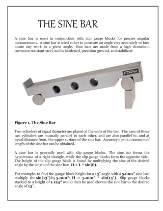
  • 1. THE SINE BAR A sine bar is used in conjunction with slip gauge blocks for precise angular measurement. A sine bar is used either to measure an angle very accurately or face locate any work to a given angle. Sine bars are made from a high chromium corrosion resistant steel, and is hardened, precision ground, and stabilized. Figure 1. The Sine Bar Two cylinders of equal diameter are placed at the ends of the bar. The axes of these two cylinders are mutually parallel to each other, and are also parallel to, and at equal distance from, the upper surface of the sine bar. Accuracy up to 0.01mm/m of length of the sine bar can be obtained. A sine bar is generally used with slip gauge blocks. The sine bar forms the hypotenuse of a right triangle, while the slip gauge blocks form the opposite side. The height of the slip gauge block is found by multiplying the sine of the desired angle by the length of the sine bar: H = L * sin(θ). For example, to find the gauge block height for a 13˚ angle with a 5.000″ sine bar, multiply the sin(13˚) by 5.000″: H = 5.000″ * sin(13˚). Slip gauge blocks stacked to a height of 1.124″ would then be used elevate the sine bar to the desired angle of 13˚.
  • 2. SINE BAR PRINCIPLES  The application of trigonometry applies to sine bar usage.  A surface plate, sine bar, and slip gauges are used for the precise formation of an angle.  It is possible to set up any angle ϴ by using the standard length of side AB, and calculating the height of side BC using BC = AB * sin(ϴ).  The angle ϴ is given by ϴ = asin(BC/AB).  Figure 1 shows a typical sine bar set up on a surface plate with slip gauge blocks of the required height BC to form a desired angle ϴ. Figure 2: Forming an Angle with a Sine Bar and Gauge Blocks
  • 3. WRINGING The term wringing refers to a condition of intimate and complete contact by tight adhesion between measuring faces. Wringing is done by hand by sliding and twisting motions. One gauge is placed perpendicular to other using standard gauging pressure then a rotary motion is applied until the blocks are lined up. In this way air is expelled from between the gauge faces causing the blocks to adhere. This adherence is caused partially by molecular attraction and partially by atmospheric pressure. Similarly, for separating slip gauges, a combined sliding and twisting motion should be used. 1. To set an angle on any sine bar, you must first determine the center distance of the sine bar (C), the angle you wish to set (A) and whether the angle is in degrees- minutes-seconds or decimal degrees. 2. Next, enter that information in the appropriate input areas below. Use a decimal point for the separator, whether the angle is in degrees-minutes-seconds or decimal degrees. 3. Hit the ‘Calculate’ button and then assemble a stack of gauge blocks (G) to equal the size that is returned. The units of the stack will match the units of the center distance (i.e., If you enter the center distance as 5 for a 5 inch sine plate, the gage block stack will also be in inches.). 4. Place these slip gauges blocks under the gauge block roll of the sine device and the desired angle is set. 5. Tighten the locking mechanism on those devices that have one and you’re ready to go. Figure 3: Uses the formula: G = C * Sin(A)
  • 4. If you just want to set an angle with a sine bar and stack of blocks, then take the sine of the desired angle on your calculator and multiply the result by the distance between the centers of the cylinders in the sine bar. Assemble a stack of blocks equal to this value and put it under one of the cylinders. SINE BAR SET-UP CALCULATION To calculate the gauge block’s height needed to set-up a sine bar to a specific angle all you have to do is take the SIN of the angle and multiply it by the sine bar length.  The length of the sine bar is the distance between the centers of the sine bar gauge pins. Figure 4. Sine Bar Example: Set up a 5.0” sine bar or sine plate to 30° SIN (30˚) = 0.5000 0.5000 x 5.0″ (sine Bar Length) = 2.5000″ Round 2.5000″ to 4 Decimal Places = 2.5000″ Gage Block Height.
  • 5. Table 1 Common Angles and heights for a 5-inch sine bar: Angle Height 5° 0.4358″ 10° 0.8682″ 15° 1.2941″ 20° 1.7101″ 25° 2.1131″ 30° 2.5000″ 35° 2.8679″ 40° 3.2139″ 45° 3.5355″ 50° 3.8302″ 55° 4.0958″ 60° 4.3301″ Types The simplest type consists of a lapped steel bar, at each end of which is attached an accurate cylinder, the axis of cylinder being mutually parallel and parallel to the upper surface of the bar. In the advanced type some holes are drilled in the body of the bar to reduce the weight and facilitate handling.[1] Sine centre A special type of sine bar is sine centre which is used for conical objects having male and female parts. It cannot measure the angle more than 45 degrees Sine table A sine table (or sine plate) is a large and wide sine bar, typically equipped with a mechanism for locking it in place after positioning, which is used to hold workpieces during operations.
  • 6. Compound sine table It is used to measure compound angles of large workpiece. In this case, two sine tables are mounted one over the other at right angles. The tables can be twisted to get the required alignment. SINE BAR USAGE To measure a known angle or locate any work to a given angle: 1. Always use a perfectly flat and clean surface plate. 2. Place one roller on the surface plate and the other roller on the slip gauge block stack of height H. 3. Let the sine bar be set to an angle ϴ. 4. Then sin(ϴ) = H/L, where L is the distance between the center. 5. Thus knowing ϴ, H can be found and any work can be set out at this angle as the top face of the sine bar is inclined at angle ϴ to the surface plate. 6. For better result both rollers must placed on slip gauge block of height H1 and H2 respectively.