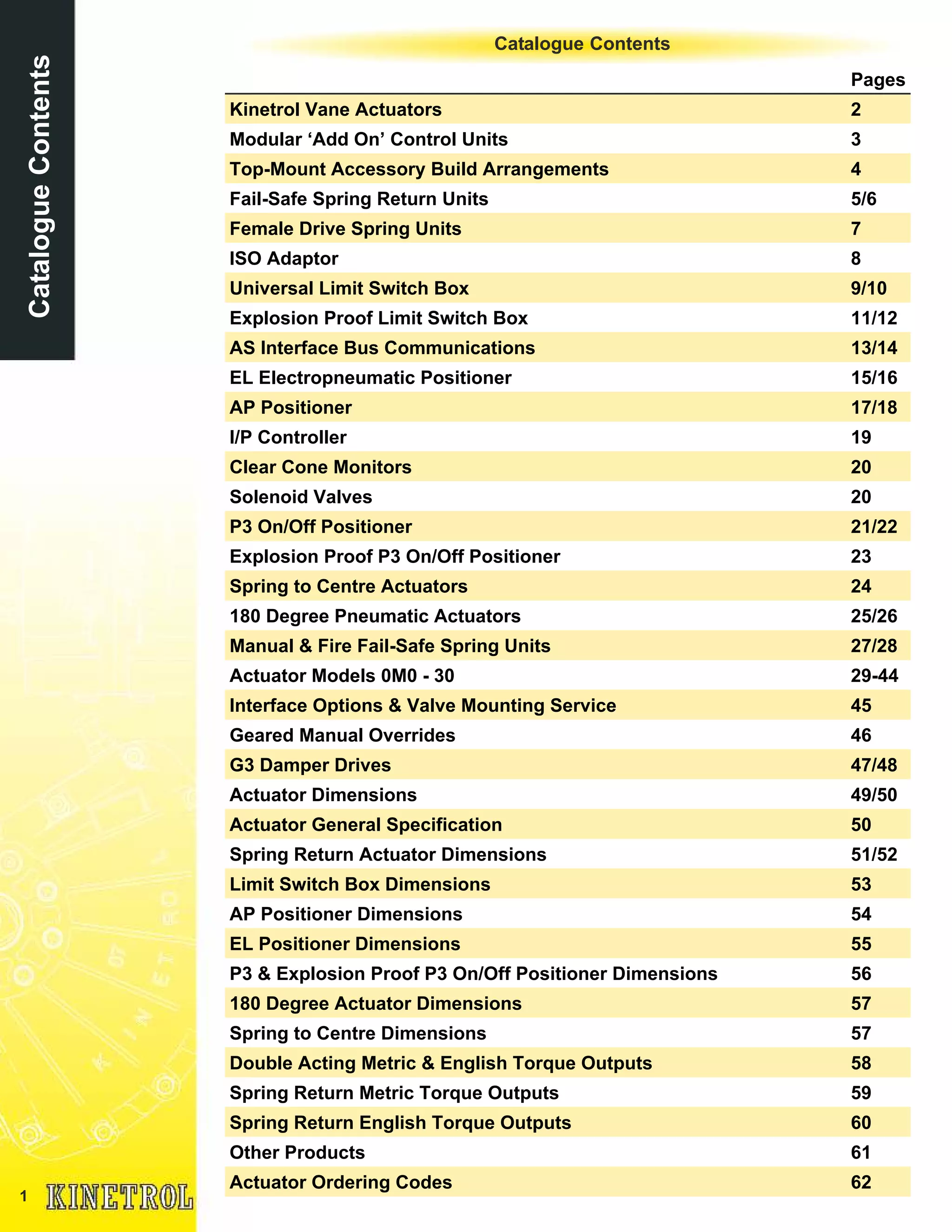
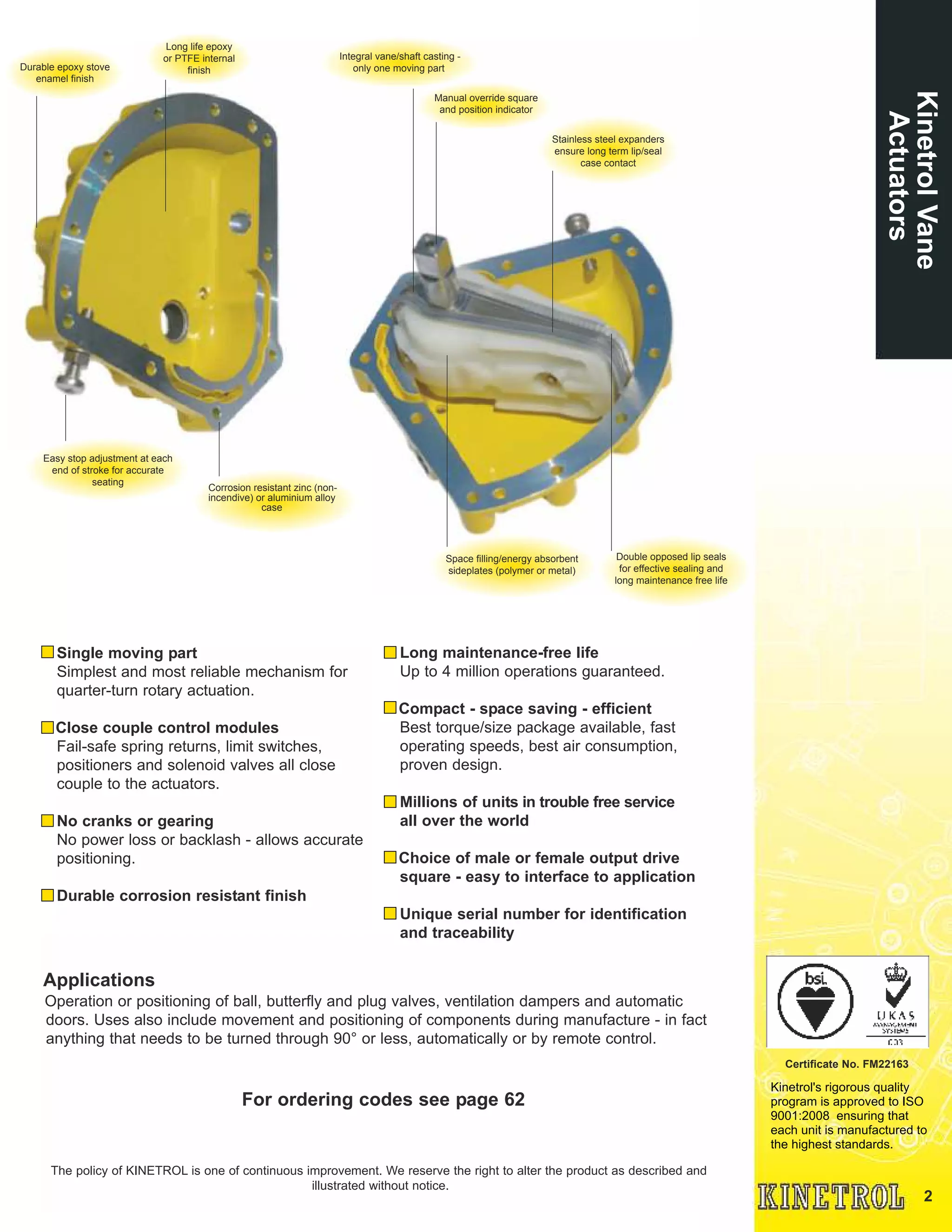
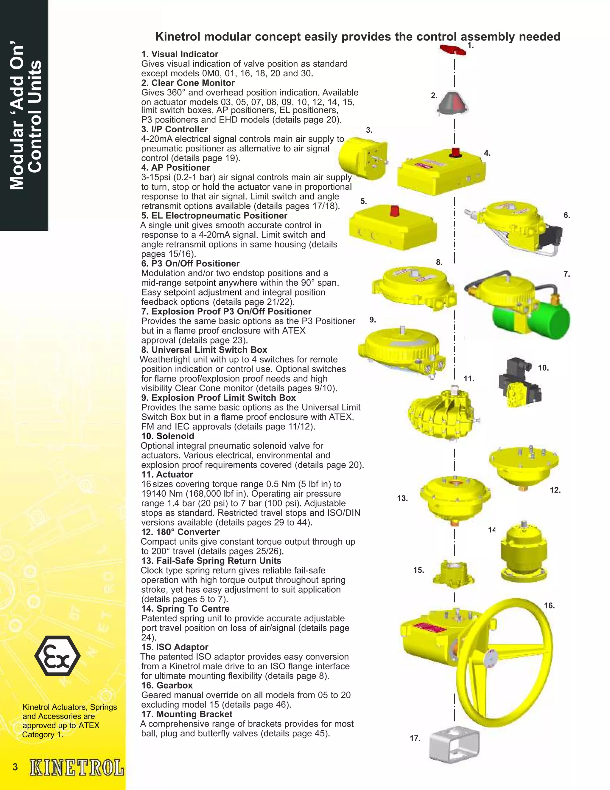
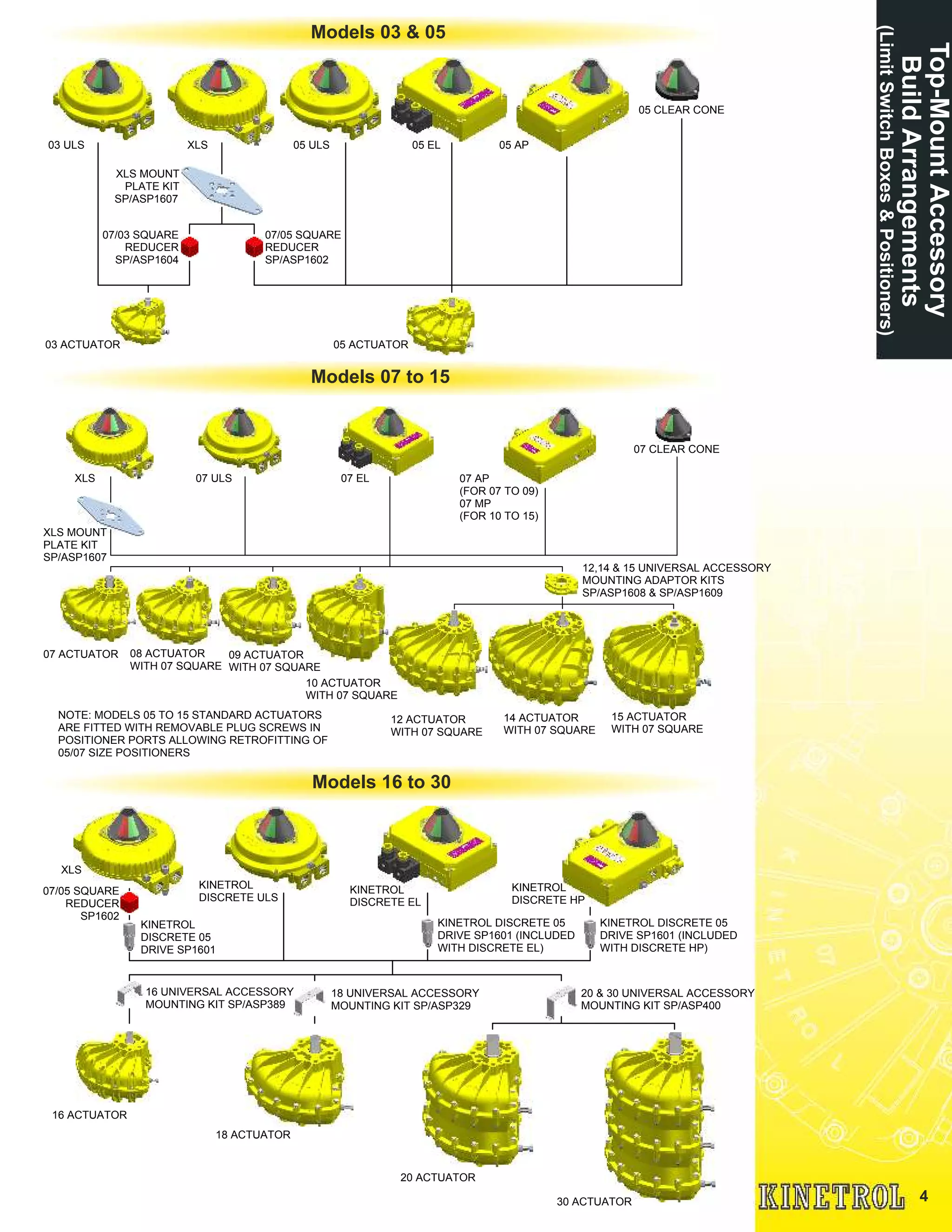
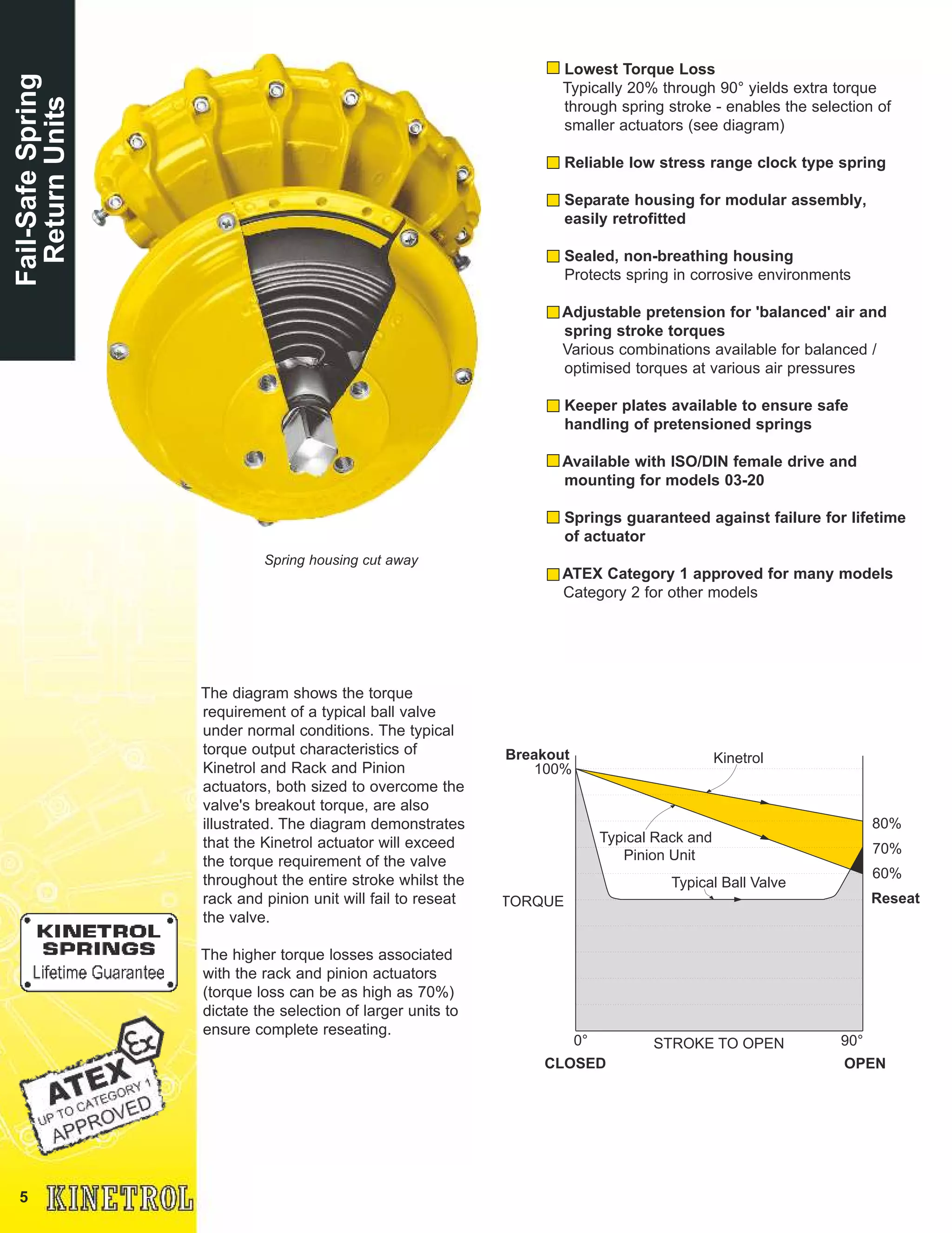
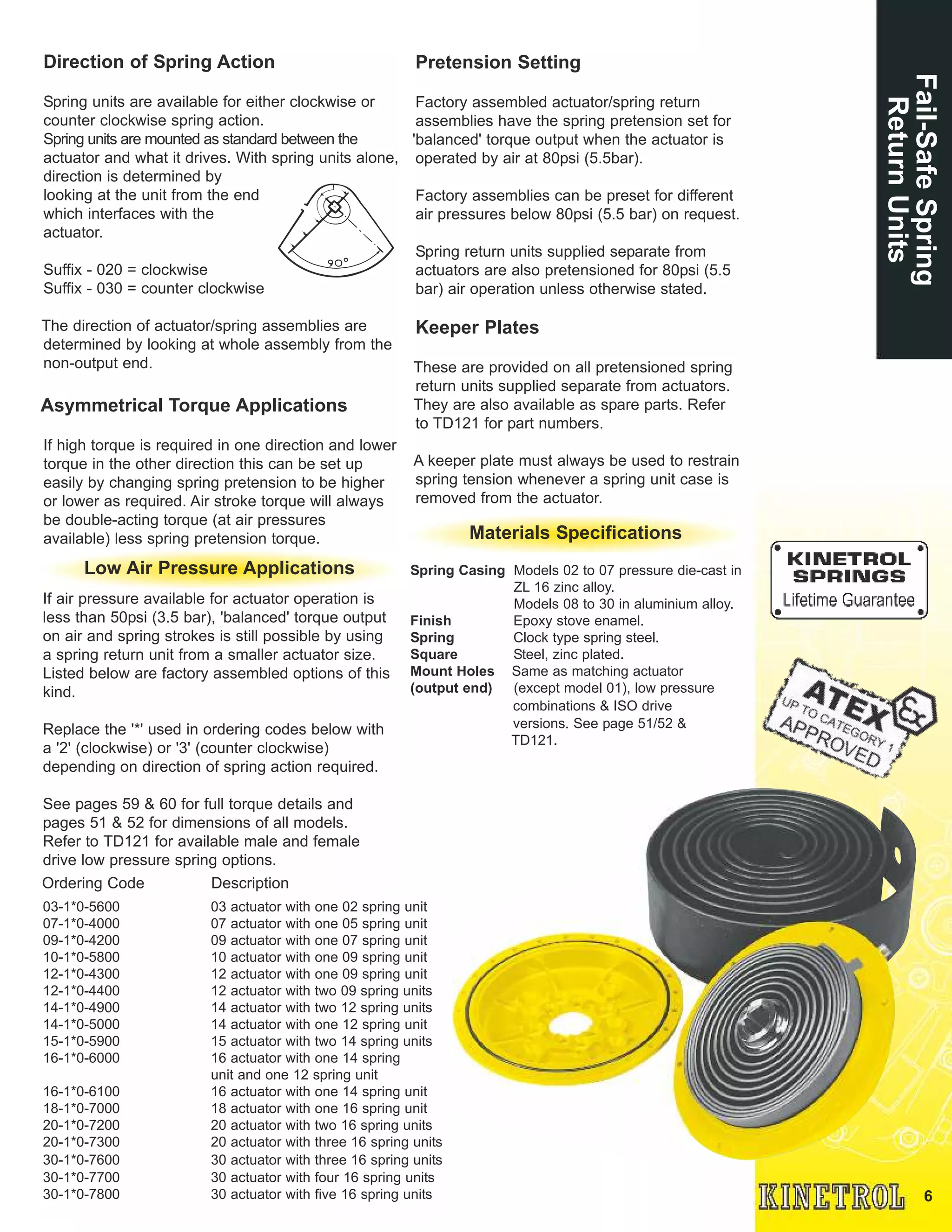
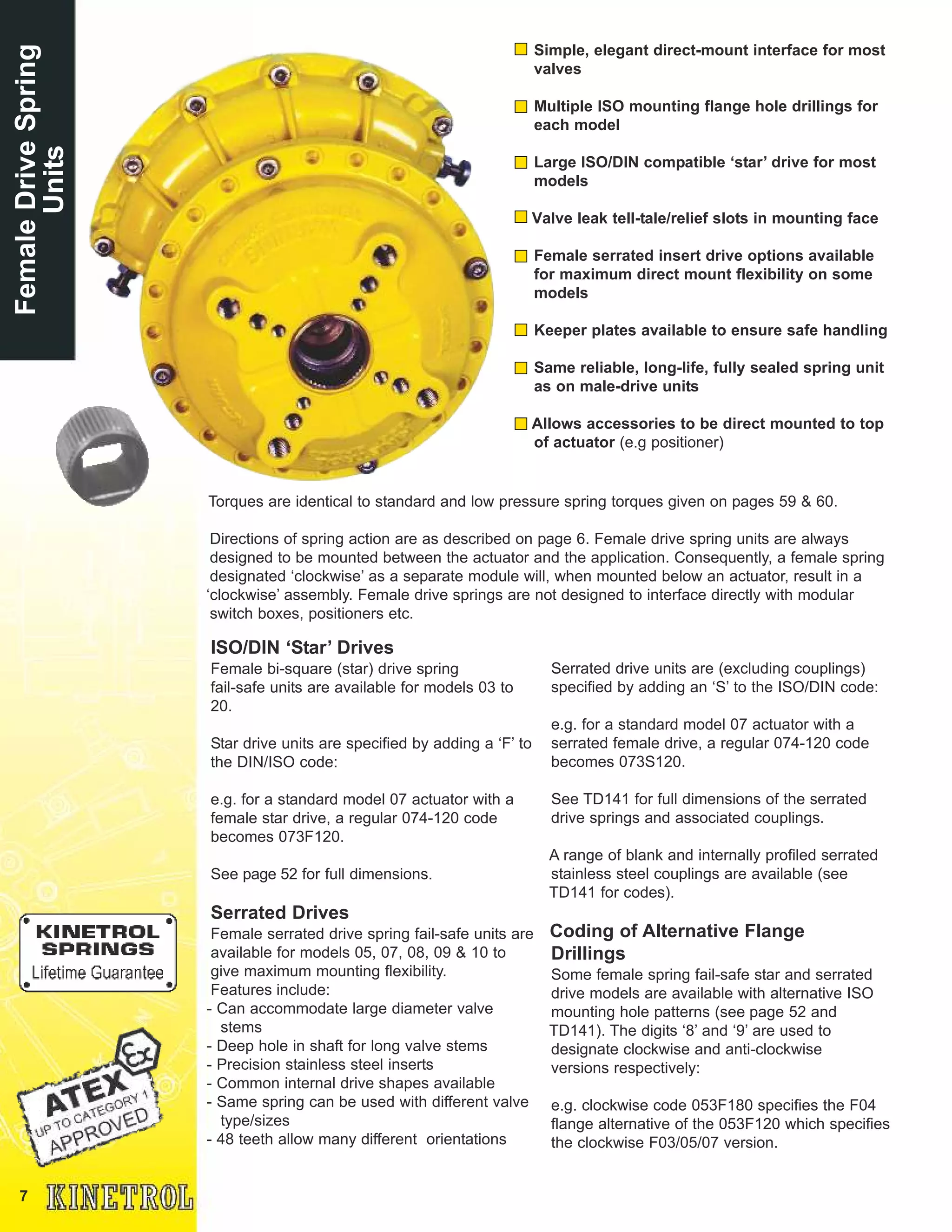
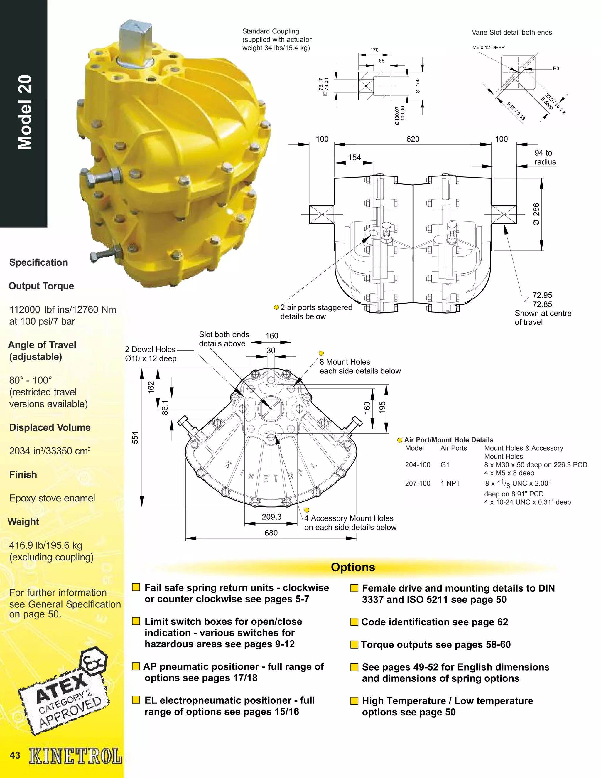
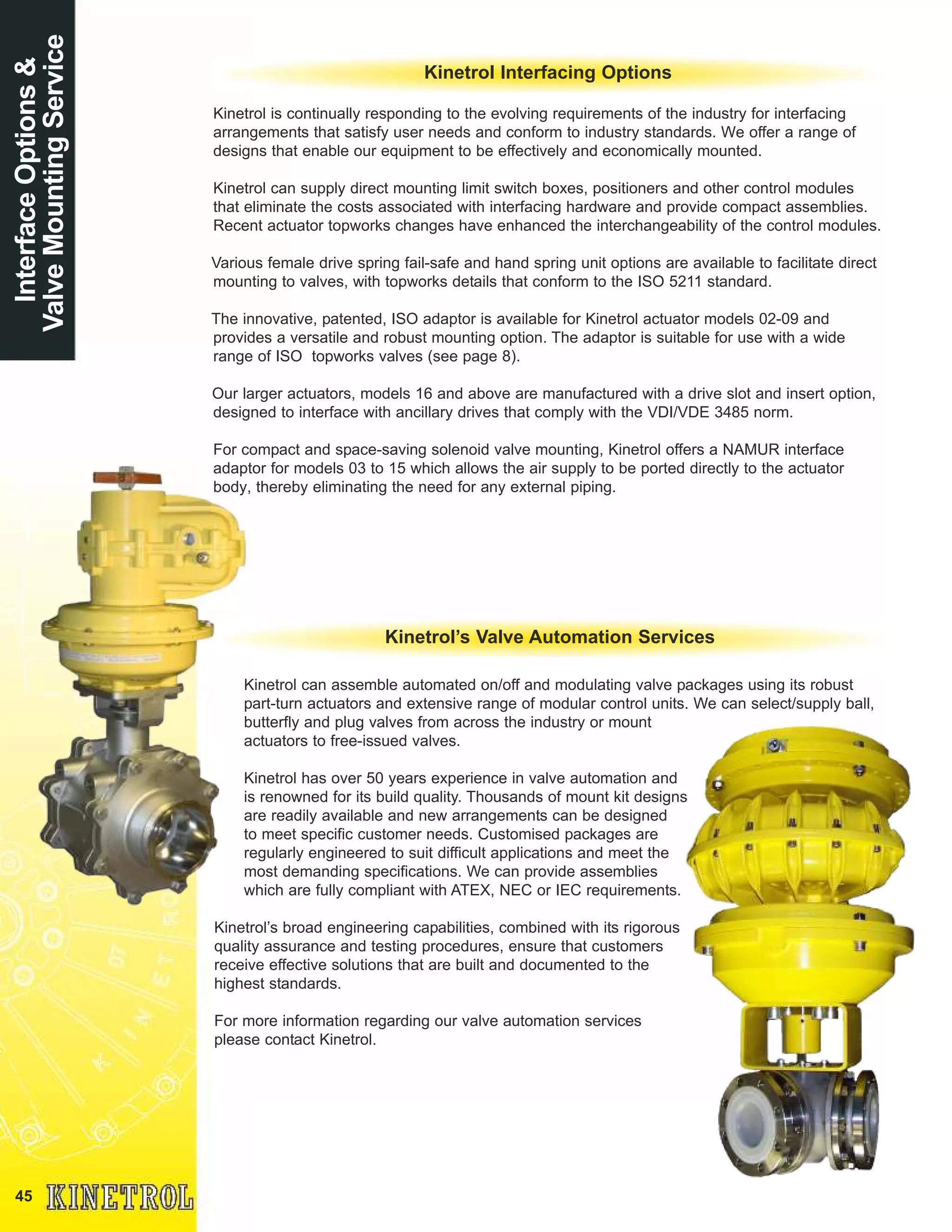
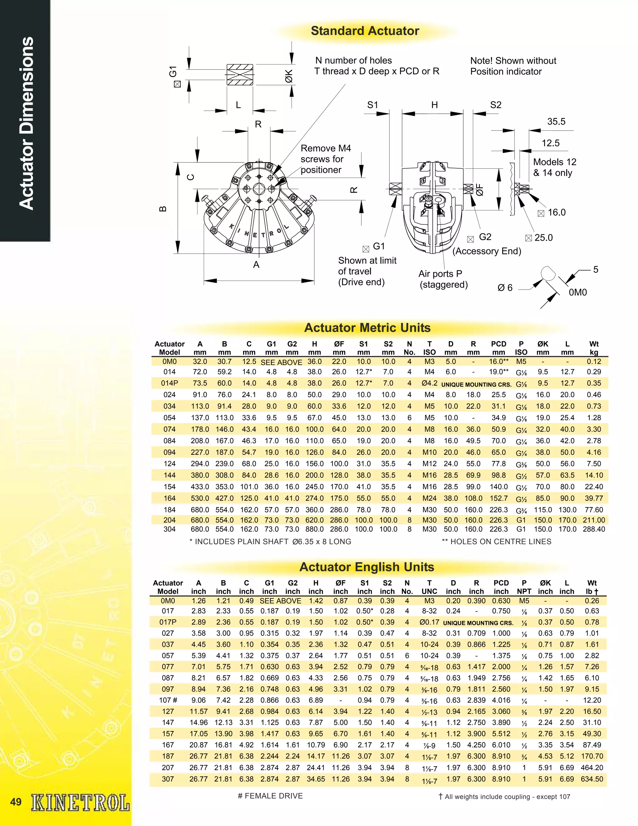
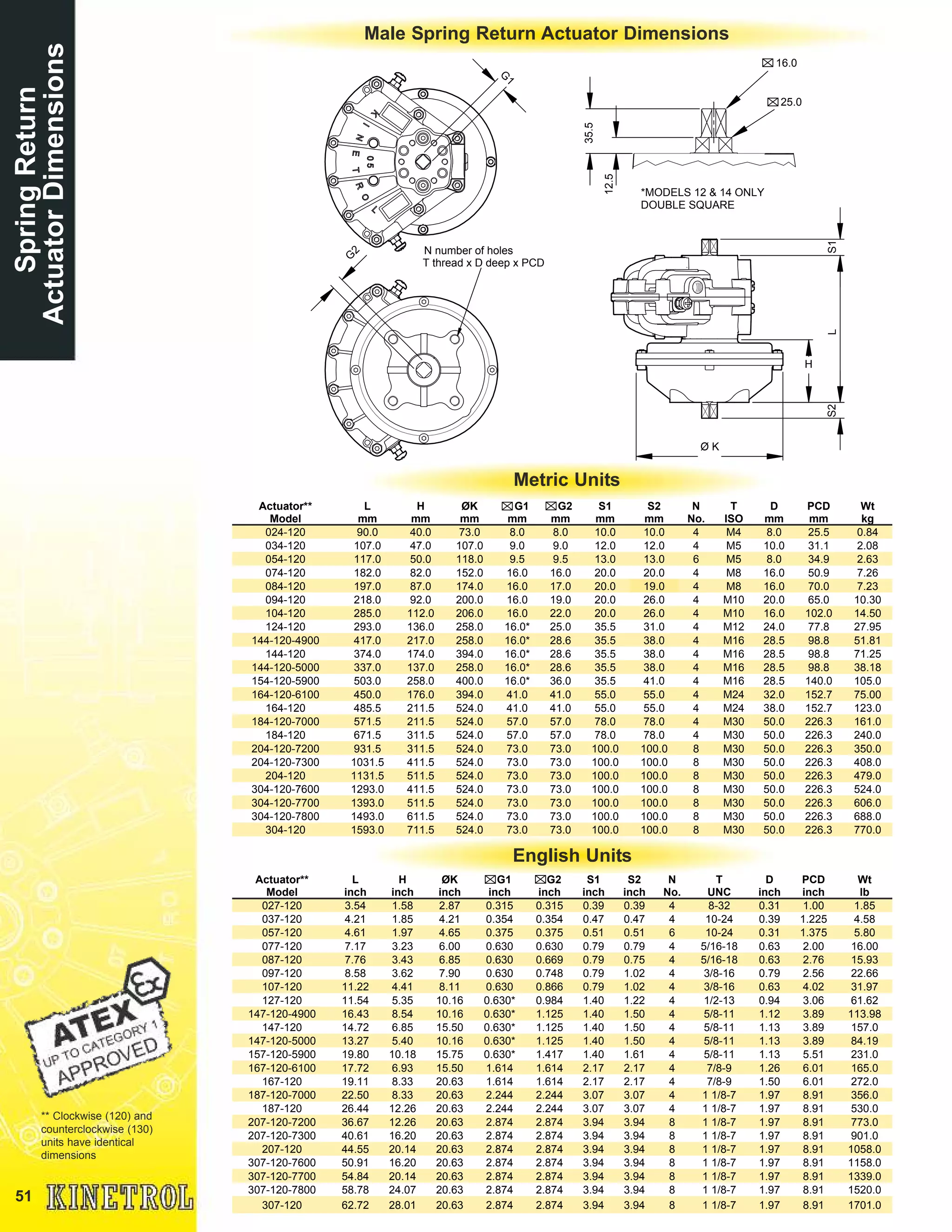
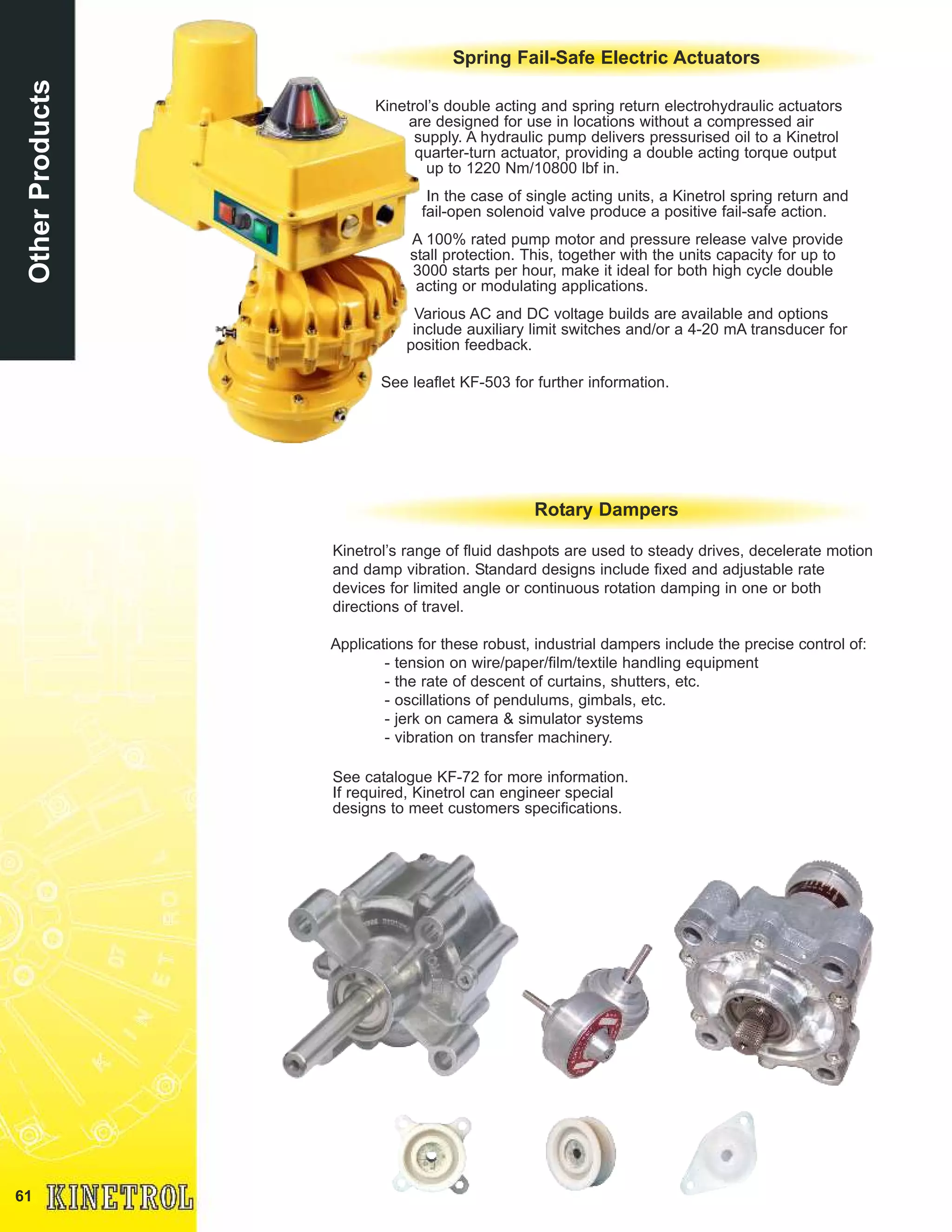
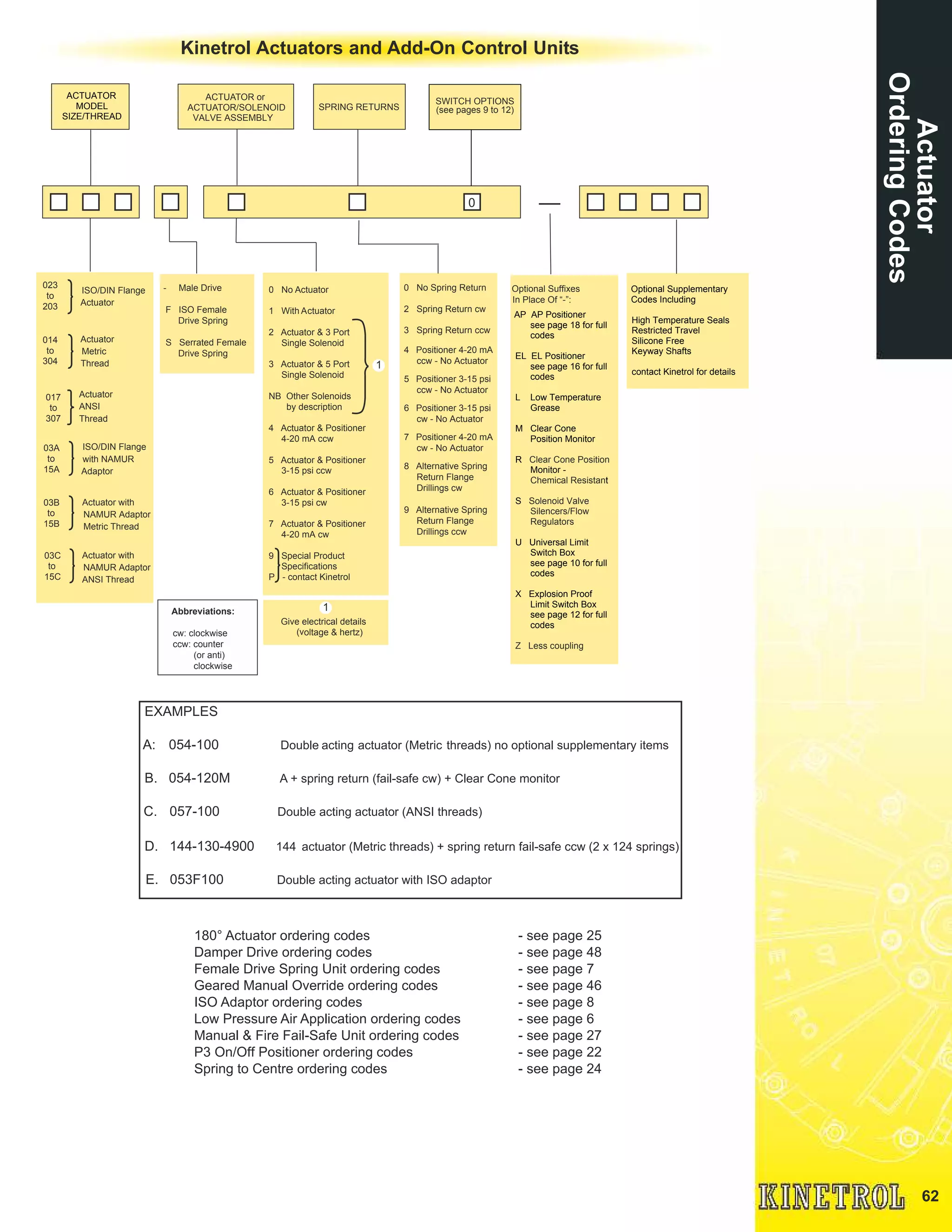
Rotary Actuators
®
1
Catalogue ContentsCatalogueContents
Pages
Kinetrol Vane Actuators 2
Modular ‘Add On’ Control Units 3
Top-Mount Accessory Build Arrangements 4
Fail-Safe Spring Return Units 5/6
Female Drive Spring Units 7
ISO Adaptor 8
Universal Limit Switch Box 9/10
Explosion Proof Limit Switch Box 11/12
AS Interface Bus Communications 13/14
EL Electropneumatic Positioner 15/16
AP Positioner 17/18
I/P Controller 19
Clear Cone Monitors 20
Solenoid Valves 20
P3 On/Off Positioner 21/22
Explosion Proof P3 On/Off Positioner 23
Spring to Centre Actuators 24
180 Degree Pneumatic Actuators 25/26
Manual & Fire Fail-Safe Spring Units 27/28
Actuator Models 0M0 - 30 29-44
Interface Options & Valve Mounting Service 45
Geared Manual Overrides 46
G3 Damper Drives 47/48
Actuator Dimensions 49/50
Actuator General Specification 50
Spring Return Actuator Dimensions 51/52
Limit Switch Box Dimensions 53
AP Positioner Dimensions 54
EL Positioner Dimensions 55
P3 & Explosion Proof P3 On/Off Positioner Dimensions 56
180 Degree Actuator Dimensions 57
Spring to Centre Dimensions 57
Double Acting Metric & English Torque Outputs 58
Spring Return Metric Torque Outputs 59
Spring Return English Torque Outputs 60
Other Products 61
Actuator Ordering Codes 62
2
Kinetrol's rigorous quality
program is approved to ISO
9001:2008 ensuring that
each unit is manufactured to
the highest standards.
Certificate No. FM22163
Single moving part
Simplest and most reliable mechanism for
quarter-turn rotary actuation.
Close couple control modules
Fail-safe spring returns, limit switches,
positioners and solenoid valves all close
couple to the actuators.
No cranks or gearing
No power loss or backlash - allows accurate
positioning.
Durable corrosion resistant finish
Long maintenance-free life
Up to 4 million operations guaranteed.
Compact - space saving - efficient
Best torque/size package available, fast
operating speeds, best air consumption,
proven design.
Millions of units in trouble free service
all over the world
Choice of male or female output drive
square - easy to interface to application
Unique serial number for identification
and traceability
Applications
Operation or positioning of ball, butterfly and plug valves, ventilation dampers and automatic
doors. Uses also include movement and positioning of components during manufacture - in fact
anything that needs to be turned through 90° or less, automatically or by remote control.
For ordering codes see page 62
The policy of KINETROL is one of continuous improvement. We reserve the right to alter the product as described and
illustrated without notice.
KinetrolVane
Actuators
Long life epoxy
or PTFE internal
finishDurable epoxy stove
enamel finish
Easy stop adjustment at each
end of stroke for accurate
seating
Integral vane/shaft casting -
only one moving part
Manual override square
and position indicator
Stainless steel expanders
ensure long term lip/seal
case contact
Space filling/energy absorbent
sideplates (polymer or metal)
Double opposed lip seals
for effective sealing and
long maintenance free life
Corrosion resistant zinc (non-
incendive) or aluminium alloy
case
1.
2.
3.
4.
5.
6.
8.
9.
10.
11.
13.
12.
15.
17.
7.
3
1. Visual Indicator
Gives visual indication of valve position as standard
except models 0M0, 01, 16, 18, 20 and 30.
2. Clear Cone Monitor
Gives 360° and overhead position indication. Available
on actuator models 03, 05, 07, 08, 09, 10, 12, 14, 15,
limit switch boxes, AP positioners, EL positioners,
P3 positioners and EHD models (details page 20).
3. I/P Controller
4-20mA electrical signal controls main air supply to
pneumatic positioner as alternative to air signal
control (details page 19).
4. AP Positioner
3-15psi (0.2-1 bar) air signal controls main air supply
to turn, stop or hold the actuator vane in proportional
response to that air signal. Limit switch and angle
retransmit options available (details pages 17/18).
5. EL Electropneumatic Positioner
A single unit gives smooth accurate control in
response to a 4-20mA signal. Limit switch and
angle retransmit options in same housing (details
pages 15/16).
6. P3 On/Off Positioner
Modulation and/or two endstop positions and a
mid-range setpoint anywhere within the 90° span.
Easy setpoint adjustment and integral position
feedback options (details page 21/22).
7. Explosion Proof P3 On/Off Positioner
Provides the same basic options as the P3 Positioner
but in a flame proof enclosure with ATEX
approval (details page 23).
8. Universal Limit Switch Box
Weathertight unit with up to 4 switches for remote
position indication or control use. Optional switches
for flame proof/explosion proof needs and high
visibility Clear Cone monitor (details pages 9/10).
9. Explosion Proof Limit Switch Box
Provides the same basic options as the Universal Limit
Switch Box but in a flame proof enclosure with ATEX,
FM and IEC approvals (details page 11/12).
10. Solenoid
Optional integral pneumatic solenoid valve for
actuators. Various electrical, environmental and
explosion proof requirements covered (details page 20).
11. Actuator
16sizes covering torque range 0.5 Nm (5 lbf in) to
19140 Nm (168,000 lbf in). Operating air pressure
range 1.4 bar (20 psi) to 7 bar (100 psi). Adjustable
stops as standard. Restricted travel stops and ISO/DIN
versions available (details pages 29 to 44).
12. 180° Converter
Compact units give constant torque output through up
to 200° travel (details pages 25/26).
13. Fail-Safe Spring Return Units
Clock type spring return gives reliable fail-safe
operation with high torque output throughout spring
stroke, yet has easy adjustment to suit application
(details pages 5 to 7).
14. Spring To Centre
Patented spring unit to provide accurate adjustable
port travel position on loss of air/signal (details page
24).
15. ISO Adaptor
The patented ISO adaptor provides easy conversion
from a Kinetrol male drive to an ISO flange interface
for ultimate mounting flexibility (details page 8).
16. Gearbox
Geared manual override on all models from 05 to 20
excluding model 15 (details page 46).
17. Mounting Bracket
A comprehensive range of brackets provides for most
ball, plug and butterfly valves (details page 45).
Kinetrol modular concept easily provides the control assembly needed
Modular‘AddOn’
ControlUnits
14.
16.
Kinetrol Actuators, Springs
and Accessories are
approved up to ATEX
Category 1.
4
07/03 SQUARE
REDUCER
SP/ASP1604
XLS MOUNT
PLATE KIT
SP/ASP1607
03 ACTUATOR 05 ACTUATOR
07/05 SQUARE
REDUCER
SP/ASP1602
05 CLEAR CONE
03 ULS XLS 05 ULS 05 EL 05 AP
Models 03 & 05
XLS
KINETROL
DISCRETE EL
KINETROL
DISCRETE 05
DRIVE SP1601
16 ACTUATOR
KINETROL
DISCRETE ULS
20 & 30 UNIVERSAL ACCESSORY
MOUNTING KIT SP/ASP400
20 ACTUATOR
30 ACTUATOR
18 ACTUATOR
07/05 SQUARE
REDUCER
SP1602
KINETROL DISCRETE 05
DRIVE SP1601 (INCLUDED
WITH DISCRETE EL)
KINETROL DISCRETE 05
DRIVE SP1601 (INCLUDED
WITH DISCRETE HP)
18 UNIVERSAL ACCESSORY
MOUNTING KIT SP/ASP329
16 UNIVERSAL ACCESSORY
MOUNTING KIT SP/ASP389
KINETROL
DISCRETE HP
Models 16 to 30
Top-MountAccessory
BuildArrangements
(LimitSwitchBoxes&Positioners)
Models 07 to 15
12 ACTUATOR
WITH 07 SQUARE
XLS 07 ULS 07 EL
XLS MOUNT
PLATE KIT
SP/ASP1607
07 ACTUATOR
07 AP
(FOR 07 TO 09)
07 MP
(FOR 10 TO 15)
07 CLEAR CONE
12,14 & 15 UNIVERSAL ACCESSORY
MOUNTING ADAPTOR KITS
SP/ASP1608 & SP/ASP1609
08 ACTUATOR
WITH 07 SQUARE
09 ACTUATOR
WITH 07 SQUARE
15 ACTUATOR
WITH 07 SQUARE
14 ACTUATOR
WITH 07 SQUARE
10 ACTUATOR
WITH 07 SQUARE
NOTE: MODELS 05 TO 15 STANDARD ACTUATORS
ARE FITTED WITH REMOVABLE PLUG SCREWS IN
POSITIONER PORTS ALLOWING RETROFITTING OF
05/07 SIZE POSITIONERS
5
Breakout
Reseat
CLOSED OPEN
100%
0° STROKE TO OPEN 90°
TORQUE
60%
70%
80%
Kinetrol
Typical Rack and
Pinion Unit
Typical Ball Valve
The diagram shows the torque
requirement of a typical ball valve
under normal conditions. The typical
torque output characteristics of
Kinetrol and Rack and Pinion
actuators, both sized to overcome the
valve's breakout torque, are also
illustrated. The diagram demonstrates
that the Kinetrol actuator will exceed
the torque requirement of the valve
throughout the entire stroke whilst the
rack and pinion unit will fail to reseat
the valve.
The higher torque losses associated
with the rack and pinion actuators
(torque loss can be as high as 70%)
dictate the selection of larger units to
ensure complete reseating.
Lowest Torque Loss
Typically 20% through 90° yields extra torque
through spring stroke - enables the selection of
smaller actuators (see diagram)
Reliable low stress range clock type spring
Separate housing for modular assembly,
easily retrofitted
Sealed, non-breathing housing
Protects spring in corrosive environments
Adjustable pretension for 'balanced' air and
spring stroke torques
Various combinations available for balanced /
optimised torques at various air pressures
Keeper plates available to ensure safe
handling of pretensioned springs
Available with ISO/DIN female drive and
mounting for models 03-20
Springs guaranteed against failure for lifetime
of actuator
ATEX Category 1 approved for many models
Category 2 for other models
Fail-SafeSpring
ReturnUnits
Spring housing cut away
6
Fail-SafeSpring
ReturnUnits
Direction of Spring Action
Spring units are available for either clockwise or
counter clockwise spring action.
Spring units are mounted as standard between the
actuator and what it drives. With spring units alone,
direction is determined by
looking at the unit from the end
which interfaces with the
actuator.
Suffix - 020 = clockwise
Suffix - 030 = counter clockwise
The direction of actuator/spring assemblies are
determined by looking at whole assembly from the
non-output end.
Asymmetrical Torque Applications
If high torque is required in one direction and lower
torque in the other direction this can be set up
easily by changing spring pretension to be higher
or lower as required. Air stroke torque will always
be double-acting torque (at air pressures
available) less spring pretension torque.
Pretension Setting
Factory assembled actuator/spring return
assemblies have the spring pretension set for
'balanced' torque output when the actuator is
operated by air at 80psi (5.5bar).
Factory assemblies can be preset for different
air pressures below 80psi (5.5 bar) on request.
Spring return units supplied separate from
actuators are also pretensioned for 80psi (5.5
bar) air operation unless otherwise stated.
Keeper Plates
These are provided on all pretensioned spring
return units supplied separate from actuators.
They are also available as spare parts. Refer
to TD121 for part numbers.
A keeper plate must always be used to restrain
spring tension whenever a spring unit case is
removed from the actuator.
Low Air Pressure Applications
Materials Specifications
If air pressure available for actuator operation is
less than 50psi (3.5 bar), 'balanced' torque output
on air and spring strokes is still possible by using
a spring return unit from a smaller actuator size.
Listed below are factory assembled options of this
kind.
Replace the '*' used in ordering codes below with
a '2' (clockwise) or '3' (counter clockwise)
depending on direction of spring action required.
See pages 59 & 60 for full torque details and
pages 51 & 52 for dimensions of all models.
Refer to TD121 for available male and female
drive low pressure spring options.
Spring Casing Models 02 to 07 pressure die-cast in
ZL 16 zinc alloy.
Models 08 to 30 in aluminium alloy.
Finish Epoxy stove enamel.
Spring Clock type spring steel.
Square Steel, zinc plated.
Mount Holes Same as matching actuator
(output end) (except model 01), low pressure
combinations & ISO drive
versions. See page 51/52 &
TD121.
03-1*0-5600 03 actuator with one 02 spring unit
07-1*0-4000 07 actuator with one 05 spring unit
09-1*0-4200 09 actuator with one 07 spring unit
10-1*0-5800 10 actuator with one 09 spring unit
12-1*0-4300 12 actuator with one 09 spring unit
12-1*0-4400 12 actuator with two 09 spring units
14-1*0-4900 14 actuator with two 12 spring units
14-1*0-5000 14 actuator with one 12 spring unit
15-1*0-5900 15 actuator with two 14 spring units
16-1*0-6000 16 actuator with one 14 spring
unit and one 12 spring unit
16-1*0-6100 16 actuator with one 14 spring unit
18-1*0-7000 18 actuator with one 16 spring unit
20-1*0-7200 20 actuator with two 16 spring units
20-1*0-7300 20 actuator with three 16 spring units
30-1*0-7600 30 actuator with three 16 spring units
30-1*0-7700 30 actuator with four 16 spring units
30-1*0-7800 30 actuator with five 16 spring units
Ordering Code Description
7
FemaleDriveSpring
Units
ISO/DIN ‘Star’ Drives
Female bi-square (star) drive spring
fail-safe units are available for models 03 to
20.
Star drive units are specified by adding a ‘F’ to
the DIN/ISO code:
e.g. for a standard model 07 actuator with a
female star drive, a regular 074-120 code
becomes 073F120.
See page 52 for full dimensions.
Serrated Drives
Female serrated drive spring fail-safe units are
available for models 05, 07, 08, 09 & 10 to
give maximum mounting flexibility.
Features include:
- Can accommodate large diameter valve
stems
- Deep hole in shaft for long valve stems
- Precision stainless steel inserts
- Common internal drive shapes available
- Same spring can be used with different valve
type/sizes
- 48 teeth allow many different orientations
Simple, elegant direct-mount interface for most
valves
Multiple ISO mounting flange hole drillings for
each model
Large ISO/DIN compatible ‘star’ drive for most
models
Valve leak tell-tale/relief slots in mounting face
Female serrated insert drive options available
for maximum direct mount flexibility on some
models
Keeper plates available to ensure safe handling
Same reliable, long-life, fully sealed spring unit
as on male-drive units
Allows accessories to be direct mounted to top
of actuator (e.g positioner)
Torques are identical to standard and low pressure spring torques given on pages 59 & 60.
Directions of spring action are as described on page 6. Female drive spring units are always
designed to be mounted between the actuator and the application. Consequently, a female spring
designated ‘clockwise’ as a separate module will, when mounted below an actuator, result in a
‘clockwise’ assembly. Female drive springs are not designed to interface directly with modular
switch boxes, positioners etc.
Serrated drive units are (excluding couplings)
specified by adding an ‘S’ to the ISO/DIN code:
e.g. for a standard model 07 actuator with a
serrated female drive, a regular 074-120 code
becomes 073S120.
See TD141 for full dimensions of the serrated
drive springs and associated couplings.
A range of blank and internally profiled serrated
stainless steel couplings are available (see
TD141 for codes).
Coding of Alternative Flange
Drillings
Some female spring fail-safe star and serrated
drive models are available with alternative ISO
mounting hole patterns (see page 52 and
TD141). The digits ‘8’ and ‘9’ are used to
designate clockwise and anti-clockwise
versions respectively:
e.g. clockwise code 053F180 specifies the F04
flange alternative of the 053F120 which specifies
the clockwise F03/05/07 version.
8
ISOAdaptor
Low cost direct mount flange and
coupling for mounting to valves with ISO
5211 drive interfaces, available for
actuator models 02, 03, 05, 07, 08 and 09
Mounting directly to standard Kinetrol
double acting actuator thereby reducing
stocking requirements
Multiple mounting hole sets in one part
International patents. The novel design
allows metric mounting screws to face in either
direction. Valve flanges with tapped holes can
easily be interfaced for the first time. Nut
recesses in flange make for easy installation
Robust epoxy coated zinc alloy adaptor
with no threads for maximum corrosion
resistance
Female drive bi-square (star) coupling is
retained by adaptor and made from zinc
plated steel (other materials available on
request)
Serrated drive versions also available.
X
W
Y
VENT
GROOVES
J
H
HEXAGON
RECESSES
International Patents
* ANSI (e.g. ASP1449) colour versions (identical dimensions) also available.
** Default 03 version
† Minimum
♦ Also mounts directly to male drive spring units
FIXED
Ultimate Mounting Flexibility
FEMALE
BI-SQUARE
G x E DEEP
(COUPLING
RETAINED)
Adaptor
Kit*
Order
Codes
ISO
Flange
Sizes
H
mm
J
mm
G
mm
E †
mm
W PCD
mm
X PCD
mm
Y PCD
mm
Weight
Kg
SP 1406 ♦ 023F120 / 023F100 F03/F05 74 5.0 11 12 6.6 50 5.5 36 - 0.13
SP 1407 ♦
023F180 / (024-100Z
fitted with SP1407)
F04 74 5.0 11 12 5.5 42 - - 0.13
SP 1449 033F100** F03/F05 84 5.0 11 12 6.6 50 5.5 36 - 0.13
SP 1454
034-100Z
fitted with SP1454
F04 84 5.0 11 12 5.5 42 - - 0.13
SP 1450 ♦ 053F100 F04/F05/F07 97 5.4 14 17 9.0 70 6.6 50 5.5 42 0.27
SP 1451 ♦ 073F100 F05/F07 140 8 17 19 9.0 70 6.6 50 - 0.53
SP 1445 ♦ 083F100 F07/F10 160 10 22 24 11.0 102 9.0 70 - 1.04
SP 1452 ♦ 093F100 F07/F10 176 10 22 24 11.0 102 9.0 70 - 1.04
9
UniversalLimit
SwitchBox
Specification
Casing
Precision diecast zinc
alloy
Finish
Epoxy stove enamel
Seals
Nitrile rubber ‘O’ ring seals
Weight
1.4 kg
Cable entry options
2 or 4 entries
M20 x 1.5 Conduit thread
or
1/2 NPS Conduit thread
4 Way plug DIN 43650A
(fits any conduit thread)
4 Way M12 Connector
(M20 Conduit thread only)
Temperature Range
Standard -20°C to +80°C
High Temp Seals
up to 100°C
Also see switch
temperatures on
page 10
Dimensions
See page 53
Offers a wide range of signalling options in a zinc alloy fully
enclosed corrosion resistant case. Available for direct
mounting onto Kinetrol rotary actuators, or discrete mounting
via an industry standard VDI/VDE interface onto any make of
rotary actuator. Easy to wire and set up with real industrial
quality robustness. Internally fitted options include AS
Interface digital communication and a 4-20mA 2-wire
modulating angle retransmit circuit.
The range of switch and terminal arrangements includes 2 or
4 switches, extra connections allowing single point
termination of wiring for limit switches and solenoid valves,
ATEX approved Eexed (Category 2) explosion proof and
Eexia intrinsically safe packages (Category 1). Integral
sealed Clear Cone Monitor and red/green Led indicator
options also give excellent external visual indication of
position.
See KF-487 for full details.
All units sealed to IP65/NEMA 4X. IP67 option available
Robust corrosion resistant epoxy painted diecast zinc alloy box
Easy and accurate setting of switch position
Available for direct mounting to Kinetrol models 03 to 15, for minimum height
Quick access - No special tools required
Discrete VDI/VDE (NAMUR) interface option for use with industry standard actuators
Two or four cable entries as standard to allow back wiring of solenoid valves
Many switch options available for general and hazardous areas
AS Interface bus circuit option inside box reads up to 4 switch inputs, drives up to
2 solenoids powered by bus only (see pages 13 & 14)
Optional Clear Cone monitor available
Integral LED indicator lamps and angle retransmit circuit options are available
Compact SPST version of type 004 available for model 02 actuator
LOAD RATINGS FOR
STANDARD MICROSWITCHES (type 004)
MULTIPLICATION FACTORS
FOR NON-RESISTIVE LOADS
Steady state tungsten lamp load - x 0.1
Steady state inductive load - x 0.2
Peak inductive load - x 1.0
Voltage Resistive Load
125 V AC 15A
250 V AC 15A
up to 12 V DC 15A
up to 24 V DC 10A
up to 48 V DC 3A
up to 250 V DC 0.25A
10
UniversalLimit
SwitchBox
Ordering Codes
For more information
see KF-487
Option B - E
AS interface options are available with both
the two and four entry Kinetrol Universal Limit
Switch Box. Options B to E allow for
different extended addressing options. For
more information on the Kinetrol AS
interface card see page 13 & 14.
Option P
Two or four way Universal Limit Switch Box
fitted with potentiometer (20K ohms
conductive plastic type).
Option R
Two or four entry Universal Limit Switch Box
fitted with angle retransmit, loop powered two
wire circuit passes 4-20mA current,
proportional to 0-90° position of actuator.
Option U
Two or four entry Universal Limit Switch Box
without AS interface card, angle retransmit
or potentiometer.
Switch Type 001
2 intrinsically safe 2 wire inductive proximity
sensors for hazardous areas (ATEX CAT 1),
-20º to 80ºC, normally closed.
Ambient temperature range -20°C to +80°C
Switch Type 002
2 pneumatic switches with 4mm (5.32”) push in
fittings (ATEX CAT 2).
Ambient temperature range -20°C to +80°C
Switch Type 003
Certificated unit to EEx ed II T6 for hazardous
areas to Zone 1 (ATEX CAT 2) 2 x 3 wire
switches for SPDT.
Ambient temperature range -20°C to +70°C
Switch Type 004
2 x 3 wire microswitches for SPDT.
Ambient temperature range -40°C to +80°C
Switch Type 005
2 x 2 wire proximity sensors 20-250 volts AC,
normally open.
Ambient temperature range -25°C to +70°C
Switch Type 006
2 x 2 wire proximity sensors 5-60 volts DC,
normally open, with Led switch status indicators.
Ambient temperature range -20°C to +80°C
Switch Type 007
4 x 3 wire microswitches for DPDT.
Ambient temperature range -40°C to +80°C
Switch Type 008
2 x 2 wire inductive slotted proximity sensors,
normally closed.
Ambient temperature range -20°C to +80°C
Switch Type 009
2 x 3 wire gold plated contacts intrinsically
safe microswitches for SPDT (ATEX CAT 1).
Ambient temperature range -20°C to +80°C
Switch Type 00E
2 x 2 wire proximity sensors 20-140 volts AC
/ 10-140 volts DC.
Ambient temperature range -25°C to +80°C
Switch Type 00N
2 x 3 wire proximity sensors 10-30 volts DC,
normally open.
Ambient temperature range -25°C to +70°C
B
C
D
E
U
R
P
0
ACTUATOR
MODEL
03 - 30
4=M20 (ISO)
7=1/2" NPS
SPRING
OPTIONS
0=NO SPRING
2=CW SPRING
3=ACW SPRING
M=CLEAR CONE MONITOR - STANDARD †
R=CLEAR CONE MONITOR - EXTRA CHEMICAL RESISTANCE †
A=CLEAR CONE MONITOR - ATEX (SWITCH OPTION 1 & 9 ONLY)
0=DIRECT MOUNT UNIT
1=DISCRETE UNIT WITH KINETROL SQUARE
2=DISCRETE UNIT WITH NAMUR INTERFACE
3=DISCRETE UNIT WITH KINETROL SQ.+HI TEMP SEALS †
4=DISCRETE UNIT WITH NAMUR INTERFACE+HI TEMP SEALS †
5=DIRECT MOUNT BOX+HI TEMP SEALS †
0= 2X3 CONNECTION TERMINAL BLOCKS
4= 3X3 CONNECTION TERMINAL BLOCKS
5= 4X3 CONNECTION TERMINAL BLOCKS †
6= MULTI-TERMINAL PCB (5x3 + 1x2) †
B=WITH ASi BUS † (See KF-496)
C=ASi EXTENDED ADDRESSING,
OUTPUTS DISABLED †
D=ASi EXTENDED ADDRESSING,
OUTPUTS ENABLED †
E=ASi EXTENDED ADDRESSING,
OUTPUTS ENABLED, SEPARATE
POWER SUPPLY †
U=WITHOUT ELECTRONICS
R=WITH ANGLE RETRANSMIT †
P=WITH POTENTIOMETER †
STANDARD SWITCH OPTIONS
0=CONTACT KINETROL FOR DETAILS
1=2x V3 i-SAFE PROXIMITY SENSORS ATEX
2=2x PNEUMATIC SWITCHES ATEX
3=2x SWITCHES EExe II T6 CERTIFIED ATEX
4=2x V3 SPDT SWITCHES †
5=2x 20-250Vac PROX. SENSORS †
6=2x 5-60Vdc PROX.SENSORS †
7=4x V3 SPDT SWITCHES †
8=2x SLOTTED PROX SENSORS †
9=2x V3 SPDT i-SAFE (GOLD PLATED) ATEX
A=4x CODE 1 SENSORS 7.530Vdc †
B=4x CODE 5 SENSORS †
C=4x CODE 6 SENSORS †
D=4x CODE 9 SWITCHES †
E=2x V3 20-140Vac / 10-140Vdc INDUCTIVE SENSORS †
F=4x CODE E SENSORS †
N=2x 10-30Vdc PNP 3 WIRE PROX. SENSORS †
† NOT AVAILABLE ON ATEX VERSIONS
0=NO LED FITTED
1=2 LED'S RED + GREEN 240 / 110 V ac †
2=2 LED'S RED + GREEN 12 / 24 V dc †
3=2 LED'S RED + GREEN WITH ASi BUS †
LH
RH
0= NO ANGLE RETRANSMIT
1= ANGLE RETRANSMIT CW †
2= ANGLE RETRANSMIT ACW †
0=PNEUMATIC SWITCH CONNECTION
1=2 ENTRIES - 2 TRANSIT PLUGS
2=2 ENTRIES - 1 TRANSIT, 1 BLANKED (R.H.)
3=2 ENTRIES - DIN PLUGS †
4=2 ENTRIES - DIN PLUG, 1 BLANKED (R.H.) †
5=4 ENTRIES - 4 TRANSIT PLUGS
6=4 ENTRIES - 3 TRANSIT, 1 BLANKED (R.H.)
7=4 ENTRIES - 4 DIN PLUGS †
8=4 ENTRIES - 3 DIN PLUGS, 1 BLANKED (L.H.) †
9=4 ENTRIES - 2 DIN PLUGS, 1 BLANKED (L.H.), 1 TRANSIT †
PLUG OPTIONS FOR AS INTERFACE †
A=M12 PLUG FOR AS INTERFACE & TRANSIT (RH)
B=M12 PLUG, M12 SOCKET WITH ASI CABLE CLAMP & TRANSIT (RH)
C=M12 PLUG FOR AS INTERFACE & BLANK (RH)
D=M12 PLUG, M12 SOCKET WITH ASI CABLE CLAMP & BLANK (RH)
Unless otherwise specified M12 plug will always be connected on the left side port
0=NO ACTUATOR
1=ACTUATOR
Further switch options are available upon request -contact Kinetrol for details
EXAMPLES:
054 - 001U001000 = 05 ULS BOX WITH 2 X V3 i-SAFE PROXIMTY SENSORS, 2 TRANSIT PLUGS & 2 X 3 WAY TERMINALS ATEX APPROVED
054 - 001R011000 = 05 ULS BOX WITH 2 X V3 i-SAFE PROXIMTY SENSORS, 2 TRANSIT PLUGS & 2 X 3 WAY TERMINALS, AR CW NOT APPROVED
074 - 004R022000 = 07 ULS BOX WITH 2 X V3 SPDT SWITCHES + 1 TRANSIT & 1 BLANKING PLUG & ANGLE RETRANSMIT ACW NOT APPROVED
074 - 004U001200 = 07 ULS BOX WITH 2 X V3 SPDT SWITCHES + 2 TRANSIT PLUGS + LED'S RED / GREEN 12 / 24 V dc NOT APPROVED
074 - 009C001000 = 07 ULS BOX WITH 2 X V3 i-SAFE MECH.SWITCHES G / PLATED, ASi WITH EXTENDED ADDRESSING OUTPUTS DISABLED + 2 TRANSIT PLUGS NOT APPROVED
094 - 124B00A00M = 09 SPRING RETURN ACTUATOR & ULS BOX WITH 2 X V3 SPDT SWITCHES + STANDARD ASi & ASi TERMINALS + M12 PLUG +TRANSIT PLUG + CLEAR CONE MONITOR NOT APPROVED
074 - 009B001300 = 07 ULS BOX WITH 2 X V3 i-SAFE MECH.SWITCHES G / PLATED, STANDARD ASi + 2 TRANSIT PLUGS & ASi TERMINALS + 2 LED’S RED & GREEN NOT APPROVED
ExplosionProofLimit
SwitchBox
The Explosion Proof Limit Switch Box offers a
wide range of signalling options in a compact
corrosion resistant aluminium alloy housing.
Available for close - mounting onto Kinetrol
actuators or discrete mounting via a Kinetrol 05
square or industry standard VDI/VDE
interface onto any make of rotary actuator. Easy
to wire and set up with true industrial robustness.
Internally fitted options include AS interface
digital communication and a 4-20mA, 2-wire,
modulating angle retransmit circuit. The range of
switches and terminal arrangements includes 2 or
4 switches and extra connections - allowing single
point termination of wiring for limit switches and
solenoid valves. This product is available to mount
on Kinetrol models 03 - 30.
Wide range of worldwide explosion proof approvals including IECEX, ATEX & FM
(for USA & Canada) - all in one device
All units protected to IP66 / NEMA 4X / TYPE 4X
Attractive, functional and part-spherical profile. Robust corrosion resistant,
Anodised & epoxy painted diecast aluminium alloy housing
Close - mount to Kinetrol actuator models 03 - 15 for low profile
Discrete Kinetrol 05 square drive insert for use with Kinetrol actuator models 16 - 30
Discrete NAMUR drive for use with VDI/VDE 3845 drive actuators
2 or 4 cable entries available to allow back wiring of solenoid valves
Up to 4 switches available for SPDT, DPDT or multiple circuit operation
Easy and accurate setting of switching position
Optional antistatic Clear Cone Monitor available
Integral angle retransmit circuit options are available
Integral AS interface bus circuit option reads up to 4 switch inputs and drives up to
2 bus powered solenoids
-40° C to +80° C ambient operating temperatures (dependent on switch options)
Positioner options available
11
12
ExplosionProofLimit
SwitchBox
Ordering Codes
Specification
NORTH AMERICAN APPROVAL
Type of US: Class I, Division 1, Gas groups A,
protection, B,C,D. Class II, Division 1, Dust groups
Explosion E,F,G. T5 NEMA 4X
Proof CANADA: Class I, Division 1, Gas
groups B,C,D. Class II, Division 1,
Dust groups E,F,G. T5 TYPE 4X.
EUROPE/GLOBAL - ATEX / IECEx APPROVAL
Protection Group II C/A21, Category 2, Gas &
concept, Dust, T5, IP66
Flame Proof ‘d’
Casing precision diecast LM24 alloy, anodised
& epoxy stove enamel.
Coupling zinc plated steel.
Seals fluoropolymer dynamic seals and
NBR static seals.
Weight 1.5 kg
Cable Entry M20 x 1.5 or 1/2” 14 NPT conduit
Options entry threads.
Dimensions see page 53
Switching Operation Conditions
Labels
IECEx & ATEX - Approval type E
FMC/U, IECEx & ATEX - Approval type F & P
For more information
see KF-619
Switch
Code
Voltage
Current
Temperature
RangeAC DC
1/A — 8 6mA -20°C to +80°C
4/7 250 48 2.4A AC/1.8A DC -40°C to +80°C
5/B 250 300 100mA -25°C to +70°C
6/C — 60 100mA -20°C to +80°C
9/D — 30 100mA -40°C to +80°C
E/F 140 140 200mA -25°C to +80°C
N — 30 100mA -25°C to +70°C
0 = STANDARD INDICATOR
A = ANTI-STATIC MONITOR
OPEN - RED / CLOSED - GREEN
0 = 2 x 3 TERMINALS
4 = 3 x 3 TERMINALS
5 = 4 x 3 TERMINALS
6 = MULTI-TERMINAL PCB (2x6 + 1x3 + 1x2)
P = POTENTIOMETER
F = ANGLE RETRANSMIT CLOCKWISE
G = ANGLE RETRANSMIT ANTI-CLOCKWISE
–
0 = WITHOUT ACT
1 = WITH ACT
0 = NO SR
2 = SR CW
3 = SR CCW
APPROVAL TYPE
E = IEC / ATEX IIC, IIB, IIA
F = FM / FMC GRPS B,C,D
P = FM GRP A
D = ASi EXTENDED ADDRESSING OUTPUTS ENABLED
E = ASi EXTENDED ADDRESSING OUTPUTS ENABLED, SEPARATE POWER SUPPLY
B = ASi BUS
C = ASi EXTENDED ADDESSING OUTPUTS DISABLED
0 = NO OPTIONS
0 = CLOSE-MOUNT (03-14 MODEL-SPECIFIC)
1 = DISCRETE KINETROL 05 SQUARE DRIVE (16-30 MODEL-SPECIFIC)
2 = DISCRETE NAMUR
3 = NO MOUNTING PARTS (NON MODEL-SPECIFIC)
NOTE: ACTUATORS 16 - 30 REQUIRE DISCRETE MOUNTING
SWITCH OPTIONS
(SUPPLIED WITH 2 STRIKERS AS STANDARD)
1 = 2 x V3 7.5-30Vdc, NC, 2 WIRE INDUCTIVE SENSORS
4 = 2 x V3 SPDT, 0-250Vac, MECHANICAL MICROSWITCHES
5 = 2 x V3 20-250Vac / 10-300Vdc NO, 2 WIRE, INDUCTIVE SENSORS
6 = 2 x V3 5-60Vdc, NO, 2 WIRE, INDUCTIVE SENSORS
7 = 4 x CODE 4 MICROSWITCHES
9 = 2 x V3 SPDT, 0-250Vac, GOLD PLATED CONTACTS
MECHANICAL MICROSWITCHES
A = 4 x CODE 1 SENSORS
B = 4 x CODE 5 SENSORS
C = 4 x CODE 6 SENSORS
D = 4 x CODE 9 MICROSWITCHES
E = 2 x V3 20-140Vac / 10-140Vdc, NO, 2 WIRE, INDUCTIVE SENSORS
F = 4 x CODE E SENSORS
N = 2 x 10-30Vdc, PNP, 3 WIRE, PROXIMITY SENSORS
X
ACTUATOR
MODEL
03 - 30
3 = DIN FLANGE STANDARD (FEMALE DRIVE)
4 = ISO (M20) THREAD
A = DIN FLANGE STANDARD WITH NAMUR ADAPTOR
B = ISO (M20) THREAD STANDARD WITH NAMUR ADAPTOR
C = ANSI (1/2" NPT) THREAD STANDARD WITH NAMUR ADAPTOR
7 = ANSI THREAD (1/2" NPT)
— = MALE
F = FEMALE
S = SERRATED
B = 2 ENTRY
D = 4 ENTRY
MOUNTING PARTS AVAILABLE:
SP1601 - 05 SQUARE DRIVE
SP1602 - 07/05 SQUARE REDUCER
SP1603 - NAMUR DRIVE
SP1604 - 07/03 SQUARE REDUCER
SP/ASP1607 - CLOSE MOUNTING KIT
SP/ASP1608 - 12/14/15 ACCESSORY MOUNTING ADAPTOR (UNDRILLED)
SP/ASP389 - MODEL 16 MOUNT KIT
SP/ASP329 - MODEL 18 MOUNT KIT
SP/ASP400 - MODEL 20/30 MOUNT KIT
NOT AVAILABLE WITH
APPROVAL TYPES
F & P
ASI + 2 OR 4 SWITCHES = 2x3 (0)
A/R + 2 SWITCHES = 2x3 (0)
A/R + 4 SWITCHES = PCB (6)
POT + 2 OR 4 SWITCHES = PCB (6)
2 SWITCHES = 2x3 (0)
4 SWITCHES = 4x3 (5)
A/R + 2 SWITCHES = PCB (6)
A/R + 4 SWITCHES = PCB (6)
POT + 2 SWITCHES = PCB (6)
POT + 4 SWITCHES = PCB (6) SEE NOTE
2 SWITCHES = 3x3 (4)
4 SWITCHES = PCB (6)
TERMINALS NEEDED FOR OPTIONS
0
WITH BACKWIRING
NO BACKWIRING
NOTE - POT + 4 SWITCHES WITH BACKWIRING
WILL NOT HAVE ENOUGH TERMINAL
CONNECTORS TO WIRE ALL NORMALLY
OPEN / NORMALLY CLOSED SWITCH
CONNECTIONS WITH 3 POT CONNECTIONS.
13
ASInterface
BusCommunications
The Actuator Sensor Interface card allows easy
digital serial communication for your sensors
and actuators, allowing your actuators to be
controlled and monitored when they are in the
field, via a single 2 wire cable.
AS interface devices are used to make up control
systems based on a two-wire communication
cable known as a bus. These can be controlled
or monitored by means of a digital signal sent via
the bus to and from a "master" device (which
can be a computer or a PLC).
The slave devices will always function in
response to commands sent by the master
device, either to actuate or to return a message
reporting the value of a sensed variable, or both.
The AS Interface specification allows 31 or fewer
slave devices to be powered by a DC voltage
fed into the same two wire cable used as the
communication bus, with allowed power
consumption adequate to drive the slave plus a
standard pneumatic solenoid valve.
An AS Interface bus can be used as the final
field link in a more complex hierarchy of devices
making up a large plant-wide control system.
Actuators and sensors must often be installed in
unprotected environments where conditions can
be demanding; the AS Interface bus can be
used as the link between these field devices and
the "indoor" equipment making up the upper part
of the control system.
The AS Interface bus is designed for on/off
control and monitoring. It is a good choice when
a simple, economical, reliable and robust
solution is required for controlling and monitoring
a series of actuators and sensors in a process
control or machine application.
AS Interface Bus
The Kinetrol AS Interface card is fitted inside the
Kinetrol Universal Limit Switch box, thus
combining the industrial quality robustness of
the box with the advantages of digital serial
communication.
The AS interface bus cable can be routed in
through the conduit entries and connected to the
internal terminal blocks. Alternatively, an M12
connector plug facing outwards from the conduit
entry can be supplied to allow quick connection
from M12 sockets or with clip on adaptations for
ribbon type yellow AS interface cables.
The Kinetrol AS Interface Card
AS Interface Card Features
AS interface 2.1 compatibility
Up to 31 units with solenoid valve on-off
control, powered and controlled via a single,
two core cable
Up to 62 units (using extended addressing)
All metal robust industrial-quality limit switch
box, direct mounted on a Kinetrol actuator
2 on/off outputs per unit
4 on/off inputs per unit
Reads mechanical switches or inductive
sensors
Retrofittable to standard Kinetrol Universal
Limit Switch Box
Can also be supplied in an explosion proof
housing and with European, North American
and Worldwide approvals
LED external indicator option
Up to 31 24V 2.5W solenoid valves can be
connected to bus with no separate power
supply
M12 connector plug option available for
instant bus connection
Cable clamping connector block for yellow
ribbon-type AS interface cable available with
M12 socket to fit onto plug option
Output short circuit protection built in
-40°C option available
14
ASInterface
BusCommunications
AS Interface Configurations
Master - Slave protocol
Up to 31 Slaves per Master
Each Slave has its own unique address
(set by user)
All Slaves can be scanned every 5
milliseconds
Baud Rate - 197 Kbits/second
Slaves may be added anywhere in the bus
Slaves may be parallel connected on the
bus, using star or spur configurations
Up to 124 inputs per bus
Up to 124 outputs per bus, 62 using the
Kinetrol device
26.5 to 31.5 Vdc, 8 A max power supply
100 m (325ft) maximum cable length
(repeaters may extend network distance)
Untwisted, unshielded, 2-wire (1.5mm2)
cable can be used
AS Interface 2.1 Specification
Kinetrol's AS Interface circuit is a slave device to allow 32 devices (usually 31 slaves plus an AS
Interface master device) to be powered and controlled via a 2-wire bus cable, with full capability to
energise one solenoid on every unit all at the same time. This is the standard (Option code B).
The AS Interface 2.1 specification also allows for an extended address option, whereby 62
addresses can be connected and powered via one bus cable. The specified limits on device
capacitance however, mean that if the full extended-address compliment of slaves all had
standard solenoid valves connected, the bus limit would be exceeded.
Kinetrol offer these options to allow use of extended addressing:
1. (Option Code C)
AS Interface circuit with extended addressing enabled and outputs disabled, to read limit switch
sensors only. If a solenoid is connected it will not function.
2. (Option Code D)
AS Interface circuit with extended addressing and outputs enabled (one solenoid per interface card),
plus added isolating relay option fitted to outputs, to allow up to 31 solenoids to be energised
simultaneously even from the bus, though up to 60 slave units may be connected to the bus. This
requires the user's control system to include a pre-programmed limit on the maximum number of
solenoids to be energised. If the system instructs too many units to switch on solenoids, they will obey,
and the bus capacitance limit will be exceeded – thus this option must be at the user’s risk with regard
to this issue.
3. (Option Code E)
AS Interface circuit with extended addressing and outputs enabled (one solenoid per interface card),
plus added relay options fitted to outputs to allow solenoid valves to be powered by a supply separate
from the AS Interface bus. This option requires a separate 24V DC power supply to each actuator, and
allows up to 60 slave units to energise their solenoids simultaneously.
AS Interface Extended Addressing
For more information
see KF-496
To order the KinetrolAS Interface card refer to codes for Universal Limit Switch Box or Explosion Proof Limit
Switch Box on pages 10 and 12.
15
Fast, smooth and precise control from a
digital circuit and proportional servo
valve
Simple time saving field set up
Quick calibration via push buttons and LED
feedback and easy reversal of rotation
sense (clockwise/counter clockwise) without
special tools or parts change.
Universal application
The unit can be mounted in any orientation
on to any quarter turn or linear application
by connection via a NAMUR or Kinetrol
square interface.
Loop powered
No separate power needed, just a 4-20mA
signal plus air supply.
Integral options - easily retrofitted
modules include:
- two wire 4-20mA isolated angle retransmit
- mechanical or inductive position indicator
switches (general or hazardous areas)
- Clear Cone high visibility indicator
- Threaded conduit entries or DIN plugs for
external connection.
Intrinsically safe approved options
Weatherproof, compact and robust metal
housing
Zero backlash coupling with easily
adjustable switch strikers
Vibration and shock resistant to 4G
Built in gauge ports/external
connections
ELElectropneumatic
Positioner
The EL positioner uses a unique low power
proportional servo valve to control the position
of a quarter-turn actuator.
The microprocessor in the loop-powered 4-
20mA position circuit reads the signal via one
channel of a 12-bit A-D converter, reads the
position voltage from the feedback
potentiometer via the second channel of the
A-D converter, and compares the two. If it
detects a position which is different from that
required by the signal, it changes the output
to the servo valve, in order to drive the
actuator in the direction required to reach the
correct position. As the actuator moves, the
feedback potentiometer voltage changes and
the microprocessor continually calculates the
adjustments required for the servo valve in
order to guide the actuator accurately into
position. The microprocessor is programmed
with a sophisticated but compact algorithm
which allows this critical dynamic valve
adjustment to be made correctly. This in turn
gives optimal results with any actuator/load
combination - slow or fast, low or high friction,
low or high inertia. All can be optimised by
tuning the PGAIN and DAMP push buttons
via the positioner circuit push buttons.
Operation
Simplified Functional Diagram of EL Positioner
The EL positioner controls airflow to an
actuator and moves it to a position determined
by a 4-20mA signal. It’s features are:
16
Actuator
Model
05 - 30
Actuator
Assembly
0= No actuator
4= Act + EL ccw
7= Act + EL cw
E L
Spring Return
or Discrete
0=No SR
2=SR cw
3=SR ccw
4=Pos only ccw
7=Pos only cw
Limit Switch
0= No LS
1= 2 x IS prox
ATEX Cat 1
4= 2 x V3 mech LS
ATEX Cat 1
6= 2 x 5-30 V dc prox*1
N= 2 x 10-30 V dc prox*1
Clear Cone
Monitor
(Optional)
M
NAMUR
(Discrete Only)
0= Kinetrol
N= NAMUR
0
DIN plug
0= Conduit Entry
C= DIN Plug(s)*1
Angle Retransmit /
ATEX Approved
0= None
1= Isolated AR
2= IS ATEX
5= IS ATEX with AR
Examples:
004-040EL000N
= discrete ccw ELwith NAMUR
drive
054-404EL0000M
= ccw EL on 054 actuator + LS +
Clear Cone
Counter clockwise on rising signal
is determined looking down on
positioner
*1NOT AVAILABLE ON IS VERSIONS
ELElectropneumatic
Positioner
The EL positioner can be directly mounted on
standard Kinetrol actuator models 05 to 15,
both double acting and spring return, giving
an assembly with no external plumbing, wiring
or mechanical connections and the best
backlash free control. Mount kits are available
for models 16,18, 20 and 30 actuators.
Alternatively, discrete versions mount on any
actuator via VDI/VDE 3845 NAMUR drive, or
Kinetrol male square, with mounting bracket.
Special adaptations for linear cylinders are also
available -� consult Kinetrol for details.
The EL Positioner ATEX approval includes the
fitting of a special version of the popular
Clear Cone high visibility monitor.
Ordering Codes
Specification
* These refer to the combination of Kinetrol
actuator with EL positioner �- not just the positioner
performance
Air Supply instrument quality (dry, clean, oil free
Class 6.4.4 ISO8573.2001), 3.5 to 7
bar (50 psi to 100 psi). Consult
Kinetrol for 5µm inlet air filter option
Signal 4�-20mA, requiring max 8V to drive
through positioner circuit (compatible
with standard 24V dc source)
Control 0-�90° positioning with one linear and
Response 10 non�-linear preselected
characteristics as standard. Consult
Kinetrol for the following versions:
i) linearisation of butterfly valve
characteristics
ii) Pre�-selected travel time extension
option (with active feedback control
of travel speed)
iii) customised responses
Sensitivity better than 0.1mA*
Hysteresis better than 0.7% of span*
Repeatability better than 0.7% of span*
Deviation less than 0.7% of span*
from Linearity
Flowrate 3.3 scfm/93 l/m @ 5.5 bar
Operating �-20° to +70°C
Temperature
Adjustments low & high points (define range),
proportional gain, velocity
proportional setpoint advance
(damping)
Weight 2.95 kg/6.5 lb
Dimensions see page 55
Materials case and cover �- zinc alloy
spool and liner �- stainless steel
Finish epoxy stove enamel
Enclosure
Rating IP65/NEMA 4X
For more information
see KF�-372
Application
Travel Times
Direct mount from EL positioner to actuator
(zero load)
Externally piped from EL positioner to actuator
(zero load)
Model 05 07 08 09 10 12 14 15
Deg/Sec 129 65 38 33 22 15 7.5 4.3
Model 07 08 09 10 12 14 15 16 18 20
Deg/Sec 76 46 38 28 18 8.6 4.3 4.1 2 1
17
The AP Positioner is designed to drive a rotary
or linear actuator to a position set by a 3-15 psi
(0.2 to 1.0 bar) signal and hold it there until the
signal changes. When a signal pressure is
applied to the diaphragm it moves the force
balance lever clockwise against the tension of
the feedback spring. This moves the spool valve,
supplying air pressure to one side of the actuator
while exhausting trapped air from the other side.
The feedback shaft follows the movement of the
actuator and turns the cam counter clockwise,
pushing the cam follower and increasing the
tension on the feedback spring until it balances
the forces on the diaphragm and moves the
spool valve to its hold position.
The input signal and desired position is
determined by the cam profile. A cam giving
0-90° output movement linearly proportional to
a 3-15 psi (0.2-1.0 bar) signal is standard, and
almost any desired characteristic can be
supplied to order; if it cannot be found in the list
of existing options contact Kinetrol.
APPositioner
The AP positioner moves an actuator to a
position set by a 3-15psi control signal
and holds it there. Its features are:
Fast, smooth, accurate response
Simple, all-mechanical function for
unbeatable reliability
Three flow options to optimise control
on all actuator sizes
Universal application
The unit can be mounted in any
orientation on to any quarter-turn or
linear application
Easy set up
Quick calibration and reversal of
rotational sense (clockwise and counter
clockwise) without special tools or parts
change
ATEX CAT 1 / IECEX approved versions
available
Easily retrofitted integral module
options include:
Two wire 4-20mA angle retransmit
(inside the same case)
Mechanical or inductive limit switches
(general or hazardous areas)
4-20mA I/P convertors (general or
hazardous areas)
Clear Cone visual position indicator
(general or hazardous areas)
DIN plug option for retransmit connection
Low (-40°C) and high (100°C)
temperature versions available
Fail hold options available
Choice of mount options - see opposite
Weatherproof, compact and robust
metal housing
Vibration and shock resistant to 4G
Built in ports for signal air supply
and gauge connections
ATEX CAT 2 Exd switch option available
90° Motion
Feedback Shaft
Feedback Cam
Spool Valve
Zero
Adjuster
Flexible
Diaphragm
Feedback
Spring
Range
Adjuster
Force Balance
Lever
To
Actuator
Exhaust
Supply
Signal
Pressure
3-15psi
Schematic
Functional
Diagram
Feedback
Linkage
Operation
18
Air Supply instrument quality (dry,
clean, oil free) 3.5 to 7 bar,
(50 psi to 100 psi) standard.
Consult Kinetrol for low
pressure application
Signal 3-15psi (0.2-1.0 bar)
standard. Consult Kinetrol
for split range, 6-30 psi etc.
Control Response 0-90° linear output
standard. Consult Kinetrol
for other characteristic cam
options
Sensitivity better than 0.7% of span*
Hysteresis better than 0.7% of span*
Deviation less than 1% of span*
from linearity
Flowrates @ 5.5 bar AP: 3.3 scfm (93nl/min)
MP: 10.0 scfm (283nl/min)
HP: 27.0 scfm (764nl/min)
Operating -20° to +80°C Standard
Temperature Range -20° to +100°C High Temp
-40° to +50°C Low Temp
Weight 2.8 kg/6.2 lb
Materials • case and cover - zinc
alloy
• spool and liner - stainless
steel
• diaphragm:
- reinforced polyurethane
(standard)
- fluorocarbon rubber
(high temp)
- silicone rubber (low temp)
• feedback spring - steel
Dimensions see page 54
Finish epoxy stove enamel
Enclosure Rating IP54
Output Torque same as double acting or
spring return actuator.
When controlling fast
movement of inertia loads
consult Kinetrol
APPositioner
The AP positioner can be directly mounted on
standard Kinetrol models 05, 07, 08, 09, 10,
12, 14 and 15 actuators, both double acting
and spring return, giving an assembly with no
external plumbing, wiring or mechanical
connections and the best in direct backlash
free control. Mount kits are available for
models 16, 18, 20 and 30.
Alternatively, discrete versions mount on any
actuator using VDI/VDE 3845 NAMUR drive,
or Kinetrol male square with mounting
brackets. Neat adaptations for linear cylinders
are also available - consult Kinetrol for details.
Specification
Travel Times
Maximum velocity (no load) at 80psi 5.5 bar
*Externally piped
Cam Options
Giving typical control characteristics. Contact
Kinetrol for details of other options or see TD112.
Ordering Codes
Maximum Vibration Tolerance 4G
I/P Converter Options see page 19
For more information
see KF-391
* These refer to the combination of Kinetrol actuator with AP
positioner - not just the positioner performance
Air Signal
Electrical
Signal
Output
Movement
Characteristic Cam No.
3-15 psi
0.2-1.0 bar
4-20mA 0-90° Linear 5-1A
3-9psi
0.2-0.6 bar
4-12mA 0-90° Linear 5-2A
6-12 psi
0.4-0.8 bar
8-16mA 0-90° Linear 5-3A
9-15psi
0.6-1.0 bar
12-20mA 0-90° Linear 5-4A
3-15 psi
0.2-1.0 bar
4-20mA 0-60° Linear 5-5A
3-15 psi
0.2-1.0 bar
4-20mA 0-45° Linear 5-6A
3-15 psi
0.2-1.0 bar
4-20mA 0-90°
Proportional
Flow
5-7A
3-9 psi
0.2-0.6 bar
4-12mA 0-90°
Proportional
Flow
5-8A
9-15 psi
0.6-1.0 bar
12-20mA 0-90°
Proportional
Flow
5-22A
3-12 psi
0.2-0.8 bar
4-16mA 0-90° Linear 5-13A
9-15 psi
0.6-1.0 bar
12-20mA 0-60° Linear 5-14A
Model 05 07 08 09 10 12 12*
Deg/Sec 180 90 53 45 33 25 32
Model 14 14* 15 15* 16* 18* 20*
Deg/Sec 10.6 13.8 6.0 7.5 22.5 11.3 5.6
Input Control
Silicone
Silicone
*
*
*
*
*
*
*
*
*
ATEX approval
S
G
* Not available with
pp
X=XBox Mount
C=Clear Cone Monitor
A=Clear Cone Monitor - ATEX
Actuator
Model
05 - 30
19
I/PController
Specification - Safe Area
Electrical Control 4-20mA
Signal
Coil Impedance 20 ohms typical
Cable Entry 16mm conduit or gland
(mini DIN plug, IP 65
with Pg9 cable gland,
6-8mm dia optional)
Air Supply 80 psi/5.5 bar nominal
Air Entry G1/8 (fitted with 6mm
pipe dia. push in
connector
Weight 1.2 kg
Dimensions see page 54
Linearity 1.5%*
Hysteresis less than 1%*
Sensitivity/Deadband less than 1%*
Supply Pressure 0.2% per psi between 80
Influence and 60 psi
Quiescent Air 3.5 l/min free air max
Consumption
Working Temperature -20°C to 80°C
Range
Instrument quality dry, clean air obligatory (Class
6.4.4 ISO8573.2001)
* These refer to the combination of Kinetrol actuator with I/P
controller - not just the positioner performance
The optional Kinetrol I/P Controller is mounted in
place of the standard diaphragm housing on the
side of the positioner case. The positioner can
still be mounted in any orientation and gives an
angular output position which is proportional to
the input current control signal between 4-20mA.
The 4-20mA signal is converted to an air
pressure by a coil and magnet and flapper valve
arrangement. This air pressure controls the
positioner in the normal way.
Zero and range adjustment is done within the
positioner in the same way as with a standard
pneumatic positioner. No adjustment is
necessary within the I/P Controller. The cover is
removed only to connect the two wires - this is
not necessary with the DIN plug option.
Specification - Hazardous Area
Electrical Control 4-20mA
Signal
Input Resistance 260 ohms at 24°C
Cable Entry Exd - M20 x 1.5 conduit
entry
FM/CSA - 1/2 NPT
conduit entry
Air Supply 50-100 psi/3.5 to 7 bar
Air Entry Exd (AP & MP) G1/4 (1/4 NPT)
(HP) G3/8 (3/8 NPT)
Working Temperature -40°C to 75°C for Exd
-55°C to 85°C for Exia
Instrument quality dry, clean air obligatory (Class
3.4.4 ISO 8573.1)
I/P Controller - Hazardous Area
Kinetrol offers various optional I/P converters
which are explosion proof or intrinsically safe
certified for use in ATEX Zones 1 & 2 or NEC
and CSA CLASS I DIVISION 1. They are
mounted directly onto Kinetrol AP positioners
with integral air supply.
Certificated as follows
ATEX (Cat 2) Explosion proof
Ex II 2G Ex d IIB+H2 T6
Ta= -40°C to 75°C
Ex II 2D Ex td A21 IP65 T85°C
Ta= -40°C to 75°C
Intrinsically safe
Ex II IG Ex ia IIC T4
Ta= -55°C to 85°C
For FM Approved version - contact Kinetrol
20
ClearConeMonitors
&SolenoidValves
Clear Cone Monitor
The optional Clear Cone provides all round high
visibility position monitoring on all limit switch boxes
and positioner models. A red/green colour coded
monitor is sealed inside a robust, clear polycarbonate
cover. Positioner models are marked with black printed
legible angle scales.
The monitor is also available directly mounted onto
actuator models 03, 05, 07, 08, 09 and 10, all EHD
units and 12, 14 & 15 using an adaptor plate.
For highly corrosive environments special cover
materials are available - contact Kinetrol for details.
Conductive ATEX approved versions (to category 1)
are also available - contact Kinetrol for details.
For dimensions see pages 53, 54, 55 & 56.
Solenoid Valves
As an option Kinetrol actuator sizes 03 to 15 can
be supplied with integral solenoid valves with NAMUR
interface. Air is ported through the actuator body via
an adaptor so no external tubing is necessary.
Standard optional solenoid valves can be converted
to 5 or 3 port versions by changing the valve body
plate supplied with the valve.
Specification
Coil Voltages AC: 50/60Hz
110v AC, 240v AC and 24v DC
For other voltages contact
Kinetrol
Electrical DIN 43650 plug with Pg9 cable
Connection gland (6-8mm dia) as standard
Manual Override extra to order
Exhaust Silencers extra to order
/ Flow Regulators
Hazardous Areas certified solenoids are
available as extras to order
Environmental to IP65 as standard
Protection
Minimum Air 2 bar
Supply
Single solenoid, 3 or 5 port, interchangeable for
double acting or spring return, NAMUR
interface. Most brands of NAMUR interface
solenoid valve can be supplied to special order.
VALVE BODY
PLATE
ADAPTOR
COIL CAN BE TURNED
IN 90° INCREMENTS
115
85
G 1/4 INLET
(PLUGGED FOR TRANSPORT)
5 PORT SOL. VALVE
(ACTUATOR VANE MOVES
ANTI-CLOCKWISE WHEN COIL IS
ENERGISED
- FOR CLOCKWISE MOVEMENT
SOL. VALVE IS TURNED THRO' 180°)
OPTIONAL EXHAUST SILENCERS
21
P3On/OffPositioner
The P3 On/Off positioner consists of an electronic
positioning circuit mounted in a robust all-metal
enclosure, which controls a ¼-turn rotary pneumatic
actuator via standard on-off solenoid valves which are
direct-mounted on the actuator’s own interface.
The P3 circuit is designed so that its assembly can be
mounted inside a standard Kinetrol limit switch box
(either ULS-type, or explosion proof XLS-type), using
only two screws. The P3 assembly includes a
feedback potentiometer and anti-backlash gear drive,
which engages with gear teeth on the limit switch
coupling, to read the actuator’s position. The limit
switch coupling, complete with gear teeth, needs to
replace the standard coupling if a standard box is being
retrofitted with a P3.
The positioner circuit is powered by the mid-point input
voltage. It functions by comparing the actual mid-point
position (read by the feedback potentiometer) with the
set position (set via an on-board preset, or a remote
preset, or a remote 4-20mA signal). The positioner
circuit uses its solid-state switched outputs to power
solenoid valves which drive the actuator towards the
position where the set position corresponds with the
actual position. When it gets there, the solenoids are
switched to hold that position.
The positioner circuit incorporates a unique power
supply allowing it to be powered by any of 24vDC,
48vDC, 115vAC or 230vAC, 50/60 Hz, without the need
for any change. The supply maintains full isolation of
the low voltage control circuit from the power input line
(up to 5Kv). Switching of the solenoid valve outputs is
achieved through opto-isolated solid state switches
which operate at all the above voltages – only the
solenoid coils themselves need to be adapted
specifically to the supply voltage. The use of solid state
switching avoids any limitations on relay contact life.
Double acting models are available as fail-free
(standard), fail-down (moves clockwise or counter
clockwise on loss of electrical power if air supply is still
present) and fail-hold (holds position on loss of electrical
and / or air supply) variants. Spring return models move
in the direction of the spring on loss of electrical or air
supply.
An optional angle retransmit (AR) circuit can be
retrofitted by plugging it into the top of the
positioner circuit and fixing with three screws. The
AR circuit is a 2-wire loop-powered 4-20mA
device, which reads the position of the
positioner’s feedback pot. It is fully functional
whether or not the positioner circuit is powered.
The feedback signal is electronically isolated
(ie. floating) relative to the low voltage positioner
circuit (which in turn is electrically isolated from
the power supply and solenoid connections).
Extra solid-state switches have been incorporated
on the positioner board to allow supply to both
solenoid valves via a single cable for movement
to the upscale position when the positioner is in
spring-return or fail-down mode, while still
allowing the positioner to control the two valves
independently for the mid position. If the mid-
position input is energised, then these extra
switches isolate the solenoids from the
upscale/downscale inputs.
The three power input lines (for up, mid, down
positions) are independently fused using plug-in
miniature fuses on the positioner circuit board.
External connections are made via a multi-option
connector board, which allows simultaneous
connection of up to four changeover limit
switches, three control supply inputs plus
neutral/negative, and a single low-voltage signal.
This connector board, like the positioner circuit
assembly, mounts in either the standard ULS or
XLS box using two screws.
If an angle retransmit circuit is fitted using the low
voltage signal terminal, optional 4-20mA inputs or
external setpoint pot wires can be connected,
either directly to the terminal block on the
positioner circuit or, if only three or less limit
switches are in use, relayed through an unused
limit switch terminal on the connector board.
The limit switch box is fitted with a ground
terminal which must be connected to a suitable
external ground.
Industrial solenoid valves which permit the use of
standard quality air supplies (instrument quality air
is not necessary), are direct-mounted on adaptor
blocks on the side of the actuator, and electrically
connected via steel-armoured flying leads with
DIN sockets on the solenoid end. At the
positioner end, they connect to two 2-way
terminal blocks on the circuit board. A range of
solenoid valve options are available, determined
by the function required, the supply voltage, and
whether or not the unit requires hazardous area
certification. Customer selection is via the order
code.
22
P3On/OffPositionerOrdering Codes
Robust modulating actuator control - tolerant of standard
quality air supplies (instrument quality air is not necessary)
via industrial solenoid valves.
Three position rotary control using only three electrical
inputs plus air supply, for filling applications etc.
Two endstop positions + adjustable mid position anywhere
in angular range of actuator (90 or 180°).
Control circuit mounts inside standard all metal industrial
quality Kinetrol ULS or XLS limit switch boxes – available
fully assembled, or (on non-explosion proof models only) for
user retrofit to existing boxes.
Direct mounting onto full range of Kinetrol ¼ turn actuators.
Namur mounting options available.
Uses direct-mounting standard solenoid valves outside box
to position actuator.
Easy adjustment of mid position set point by
switch–selectable choice of methods: on-board pot, remote
pot or 4-20mA input signal.
Explosion proof options available (approved to IECEX,
ATEX) by use of XLS housing plus standard explosion proof
solenoid valves (see page 23).
All new positioner circuit – runs on 24vDC, 48vDC,
115vAC or 230vAC power without any adjustment.
- Solid-state universal-voltage solenoid switching -no
mechanical contacts.
- Three separate on-board mains fuses for three inputs.
- Switchable selection of mid-point setting method (on-board
preset, remote preset, remote 4-20mA signal).
- Switchable selection of double acting or spring return
operating mode.
- Power input isolated from signal inputs and outputs for all
voltage options.
- Moulded reinforced plastic internal circuit cover for
insulated safety.
- Positioner has user-adjustable zero, span, deadband
and damping parameters via preset pots for easy
optimisation of positioning performance.
- Damping parameter gives velocity-proportional setpoint
advance to allow better stabilisation of fast-moving or
high-inertia loads while maintaining resolution and
repeatability.
Retrofittable isolated loop-powered 4-20mA
angle-retransmit circuit available – just plugs in inside
same enclosure – with its own user-adjustable zero and
span presets.
Specification
Compatible Actuator models 05 to 15
Sizes
Supply Voltages 230 V Ac ± 10%,50 or 60 Hz
115 VAc ± 10%, 50 or 60 Hz
24 V Dc ± 10%
48 V Dc ± 10%
Power Consumption positioner 1.5W max.
solenoids 5 VAmax. per
solenoid.
Operating 0 to +55°C
Temperature Range (limited by solenoid valve
specification)
explosion proof option see
page 23
Selectable External 4-20mA - impedance 250
Inputs ohm.
Potentiometer - minimum
resistance 10K ohm.
Positioner Performance linearity -
better than 1% of range
deadband -
0.1 to 3% of range
repeatability -
better than 1% of range
Optional 2-wire Angle supply voltage -
Transducer 8.5 to 27v DC.
output -
4-20mA. linearly proportionate
to angular position, electrically
isolated from all other inputs
and outputs
functions with or without
positioner circuit energisation
Dimensions see page 56
For more information
see KF-633
Actuator size 05
must be fitted with
flow regulators
SWITCH OPTIONS
(SUPPLIED WITH 2 DOGS AS STANDARD)
0 = NO SWITCHES
1 = 2 x V3 PROXIMITY SENSORS
4 = 2 x V3 SPDT SWITCHES
5 = 2 x 20-250Vac, 10-300Vdc PROXIMITY SENSOR
6 = 2 x 5-60Vdc PROXIMITY SENSOR
7 = 4 x V3 SPDT SWITCHES
9 = 2 x V3 SPDT GOLD PLATED CONTACTS
A = 4 x V3 PROXIMITY SENSORS
B = 4 x 20-250Vac, 10-300Vdc PROXIMITY SENSOR
C = 4 x 5-60Vdc PROXIMITY SENSOR
D = 4 x V3 SPDT GOLD PLATED CONTACTS
E = 2 V3 20-140Vac, 10-140Vdc PROXIMITY SENSOR
F = 4 V3 20-140Vac, 10-140Vdc PROXIMITY SENSOR
N = 2 V3 10-30Vdc 3-WIRE PROXIMITY SENSOR
DOUBLE ACTING / SPRING
RETURN
2 = SR CW
3 = SR CCW
4 = DA CCW ON SIGNAL RISE
7 = DA CW ON SIGNAL RISE
0 = WITHOUT ACT
1 = WITH ACT
- = MALE
F = FEMALE
S = SERRATED
DOUBLE ACTING FAIL MODE
H = FAIL-HOLD
- = FAIL-FREE (STANDARD)
D = FAIL-DOWN
1 = CLOSE / DIRECT MOUNT
2 = DISCRETE MOUNT KINETROL 05 SQUARE
3 = DISCRETE MOUNT NAMUR INTERFACE
FLOW REG / SILENCER OR AR
0 = NO FRS OR AR
1 = FRS
2 = FRS + AR
3 = AR
SUPPLY VOLTAGE
0 = 240Vac
1 = 115Vac
2 = 24Vdc
3 = 48Vdc
APPROVAL TYPE
0 = STANDARD BOX (ULS)
4 = ISO THREAD (M20)
3 = DIN FLANGE (M20 - FEMALE DRIVE)
7 = ANSI THREAD (1/2" NPT ON XLS, 1/2" NPS ON ULS)
P 3 -
}
0 = STANDARD INDICATOR
A = ANTI-STATIC MONITOR
M = MONITOR
C = CHEMICAL RESISTANT MONITOR
NOT AVAILABLE WITH
APPROVAL TYPES E, F &P}
ACTUATOR
MODEL
05 - 15
23
ExplosionProof
P3On/OffPositioner
The explosion proof P3 on/off
positioner offers a robust three
position rotary control device with a
fast, smooth, accurate response in
a compact corrosion resistant,
aluminium housing.
The unit is available ATEX approved
to Category 2 and offers four
voltages, many switch options and
angle position feedback. Available
for close mounting on Kinetrol
actuator models 05 to 15 or discrete
mounting via a Kinetrol 05 square or
NAMUR drive.
European / Global Protection
ATEX / IECEX Approval
Exd Group IIC Category 2
Gas & Dust T5, IP66
Voltages 240 V Ac, 115 VAc
48 V Dc, 24 V Dc
Working -20°C to +60°C
Temperature Range
Power Consumption positioner 1.5 W max.
solenoids 5 VAmax. per
solenoid.
Selected External 4-20mA - impedance
Inputs 250 ohm.
potentiometer - minimum
resistance 10K ohm.
Casing precision diecast LM24 alloy,
anodised & epoxy stove enamel.
Coupling zinc plated steel or stainless
steel option.
Positioner Performance linearity -
better than 1% of range
deadband -
0.1 to 3% of range
(subject to optimisation
of speed, deadband and
damping).
Optional 2-wire Angle supply voltage -
Transducer 8.5 to 27v Dc
output -
4-20mA, linearly proportionate
to angular position, electrically
isolated from all other inputs
and outputs
functions with or without
positioner circuit energisation
Dimensions see page 56
Ordering Codes
Specification
Actuator size 05
must be fitted with
flow regulators
SWITCH OPTIONS
(SUPPLIED WITH 2 DOGS AS STANDARD)
0 = NO SWITCHES
1 = 2 x V3 PROXIMITY SENSORS
4 = 2 x V3 SPDT SWITCHES
5 = 2 x 20-250Vac, 10-300Vdc PROXIMITY SENSOR
6 = 2 x 5-60Vdc PROXIMITY SENSOR
7 = 4 x V3 SPDT SWITCHES
9 = 2 x V3 SPDT GOLD PLATED CONTACTS
A = 4 x V3 PROXIMITY SENSORS
B = 4 x 20-250Vac, 10-300Vdc PROXIMITY SENSOR
C = 4 x 5-60Vdc PROXIMITY SENSOR
D = 4 x V3 SPDT GOLD PLATED CONTACTS
E = 2 V3 20-140Vac, 10-140Vdc PROXIMITY SENSOR
F = 4 V3 20-140Vac, 10-140Vdc PROXIMITY SENSOR
N = 2 V3 10-30Vdc 3-WIRE PROXIMITY SENSOR
DOUBLE ACTING / SPRING
RETURN
2 = SR CW
3 = SR CCW
4 = DA CCW ON SIGNAL RISE
7 = DA CW ON SIGNAL RISE
0 = WITHOUT ACT
1 = WITH ACT
- = MALE
F = FEMALE
S = SERRATED
DOUBLE ACTING FAIL MODE
H = FAIL-HOLD
- = FAIL-FREE (STANDARD)
D = FAIL-DOWN
1 = CLOSE / DIRECT MOUNT
2 = DISCRETE MOUNT KINETROL 05 SQUARE
3 = DISCRETE MOUNT NAMUR INTERFACE
FLOW REG / SILENCER OR AR
0 = NO FRS OR AR
1 = FRS
2 = FRS + AR
3 = AR
SUPPLY VOLTAGE
0 = 240Vac
1 = 115Vac
2 = 24Vdc
3 = 48Vdc
APPROVAL TYPE
E = IEC / ATEX IIC, IIB, IIA (XLS)
4 = ISO THREAD (M20)
3 = DIN FLANGE (M20 - FEMALE DRIVE)
7 = ANSI THREAD (1/2" NPT ON XLS, 1/2" NPS ON ULS)
P 3 -
}
0 = STANDARD INDICATOR
A = ANTI-STATIC MONITOR
M = MONITOR
C = CHEMICAL RESISTANT MONITOR
NOT AVAILABLE WITH
APPROVAL TYPES E, F &P}
ACTUATOR
MODEL
05 - 15
24
A patented part-turn rotary actuator that is driven
to an end stop, in either direction, from an initial
centre position and is spring returned to an
accurate and positive mid point when the air
supply is removed. The mid-position can be set
mechanically anywhere in the actuator’s travel
range.
The spring to centre assemblies consist of one
double acting actuator fitted with two or more
opposing clock type springs contained within a
single housing. Controlled with a dual coil, 5/3
solenoid valve (or two 3/2 single coil valves)
which, when totally de-energised, allow the
springs to precisely centre the actuator against
physical stops. When either coil is energised the
actuator will travel towards one of its end stops.
As the vane moves towards an end stop the air
stroke torque reduces as the spring torque
increases and vice versa. When the coil is de-
energised the vane will spring return to its original
centre position. The usual ‘centre’ position will be
in the middle of the actuator’s 0 - 90 degree travel,
but this can easily be adjusted to any mid-stroke
location. A vernier scale on the adjustable plate
(see attached picture) permits precise mid-
position setting to within 1 degree.
SpringtoCentre
Actuators
For dimensions see page 57
(Actuator should be mounted to
application to enable adjustable centre
position and stationary end points)
Reliable low stress clock type springs.
Sealed, non-breathing housing protects
spring in corrosive environments.
Available in models 05 to 18
(excluding 15).
Stroke up to 100°
(200° option available - contact Kinetrol)
Mid position can be set mechanically
anywhere in the actuator’s travel range
using ‘vernier’ type scale.
Self contained spring assembly which can
be easily removed without a keeper plate.
Can be used in aggressive or hazardous
environments without the need for
complex or sensitive instruments.
Can be fitted with high temperature seal
option for up to 100°C
* Start torque when angle adjusted to mid position
Note: can be ordered without actuator eg. 050-0205
Actuator
Model *Start — Finish *Start — Finish
050-1205 19.2 — 17.5 170.0 — 169.9
070-1205 49.6 — 42.4 412.0 — 375.2
090-1205 99.0 — 93.8 876.0 — 830.1
120-1205 221.0 — 204.0 1956.0 — 1805.5
140-1205 533.0 — 478.0 4717.0 — 4230.6
160-1205 1009.0 — 933.0 8930.0 — 8257.7
180-1205 2686.0 — 2417.0 23771.0 — 21392.2
Torque - Nm
Based on 5.5 bar
Torque - lbf ins
Based on 80 psi
25
Simple compact unit
No external moving parts
Unique linkage design
converts to 180° travel
120° option available
Constant gear-up ratio through travel range
Hence constant output torque
Rolling contact linkage mechanism
Ensures low wear, long life, low friction
Linkage sealed for life
Protected from the environment, long
maintenance free life
Compatible with all Kinetrol modules
Direct mounted spring returns, limit switch
boxes, positioners etc.
Adjustable endstops
Kinetrol’s 180° actuator is produced by adding a 2:1 step-up linkage onto the output shaft of
well proven 90° vane actuators.
Factory fitted, direct mount linkage units are available to suit model 02, 03, 05, 07, 09, 12, 14
and 16 actuators, giving a neat single unit with no mount kits or brackets. The linkage’s unique
geometry gives constant 2:1 step-up so that the output torque remains constant throughout the
actuator's travel.
The all-steel mechanism of the linkage employs rolling contacts to minimise frictional losses and
wear, and to maximise life. The linkage is lubricated for life, and encased in a robust, fully sealed,
die cast alloy casing. Exterior surfaces are protected by a corrosion resistant epoxy stove
enamel finish. Standard adjustable endstops on the 90 degree actuator can be used to set the
angle of travel. The other end of the 90 degree actuator allows the full range of Kinetrol modular
accessories to be fitted directly.
120degree actuators are also available with adjustable end stops to give up to 133° of travel for
the above model range - contact Kinetrol for details.
Operation
180DegreePneumatic
Actuators
To order a 180° actuator, add a '1' to the end of the code for the 90° actuator on which it is based
and a '2' for a 120° actuator.
Examples:
To order an 074 cw spring return actuator plus 180° linkage, use code: 074-1201.
To order an 074 cw spring return actuator plus 120° linkage, use code: 074-1202.
Ordering Codes
26
180DegreePneumatic
Actuators
Actuator
Model
1.4 2.0 2.8 3.5 4.1 4.8 5.5 6.2 6.9
02-1001 0.6 1.1 1.6 2.2 2.7 3.2 3.7 4.2 4.8
03-1001 1.3 2.4 3.5 4.6 5.6 6.7 7.8 8.8 10.0
05-1001 3.2 5.2 7.2 9.3 11.3 13.6 15.6 17.8 19.9
07-1001 7.9 12.6 17.6 22.6 27.6 33.0 38.4 43.2 48.8
09-1001 16.3 20.0 37.1 47.6 58.0 69.2 80.4 91.2 103.0
12-1001 37.5 60.8 84.4 108.0 131.0 156.0 181.0 202.0 226.0
14-1001 97.2 151.0 206.0 262.0 316.0 375.0 434.0 488.0 542.0
16-1001 235.0 357.0 479.1 605.7 727.7 849.8 976.3 1098.4 1220.4
Pressure (bar)
Double Acting Torques/Metric Units Nm
Double Acting Torques/English Units lbf ins
Actuator
Model
20 30 40 50 60 70 80 90 100
02-1001 5.6 10 14 19 24 28 33 37 42
03-1001 12 21 31 40 50 59 69 78 88
05-1001 28 46 64 82 100 120 138 157 176
07-1001 70 112 156 200 244 292 340 384 432
09-1001 144 236 328 420 512 612 712 808 912
12-1001 332 540 748 960 1160 1376 1588 1792 2000
14-1001 860 1340 1820 2320 2800 3320 3840 4320 4800
16-1001 2080 3160 4240 5360 6440 7520 8640 9720 10800
Pressure (psi)
Spring Return Torques/English
Units lbf ins
Actuator
Model
Position
of air OR
spring
stroke
50 60 70 80
02-1201 Start 10.3 12.2 14.1 16.0
Finish 4.6 6.8 9.5 12.5
03-1201 Start 29.6 33.4 37.2 43.7
Finish 8.7 13.7 19.0 24.7
05-1201 Start 44 51 61 70
Finish 28 38 49 59
07-1201 Start 103 126 146 171
Finish 67 92 116 143
09-1201 Start 205 251 300 351
Finish 169 215 266 315
12-1201 Start 486 595 693 802
Finish 374 479 585 688
14-1201-4900 Start 1200 1420 1670 1780
Finish 969 1200 1400 1500
16-1201 Start 3069 3534 3998 4463
Finish 1605 2197 2788 3380
Pressure Setting (psi)
For dimensions see page 57
Spring Return Torques/Metric Units Nm
Actuator
Model
Position
of air OR
spring
stroke
3.5 4 4.5 5 5.5
02-1201 Start 1.1 1.3 1.4 1.6 1.8
Finish 0.5 0.7 0.9 1.2 1.4
03-1201 Start 3.3 3.7 4.0 4.3 4.9
Finish 1.0 1.5 1.9 2.2 2.8
05-1201 Start 4.9 5.5 6.2 7.0 7.9
Finish 3.2 4.0 4.9 5.8 6.7
07-1201 Start 11.6 13.5 15.5 17.4 19.3
Finish 7.5 9.5 11.6 13.8 16.1
09-1201 Start 23.2 27.4 31.1 35.3 39.5
Finish 19.1 23.2 27.0 31.4 35.6
12-1201 Start 55.1 64.8 75.6 81.1 90.4
Finish 42.2 52.0 60.0 68.9 77.5
14-1201-4900 Start 135.0 156.0 178.0 195.0 201.0
Finish 109.0 131.0 148.0 164.0 170.0
16-1201 Start 346.8 391.0 426.0 465.0 504.3
Finish 181.4 237.0 282.0 332.0 381.9
Pressure Setting (bar)
27
ISO5211 female drive & ATEX Category 2 approved options available for models 02, 03, 05
and 07
Clockwise or counter clockwise 90° spring action
Spring housing sealed to IP65 to protect from internal corrosion
Bi-square (star) and serrated female drive options available
Manual&FireFail-Safe
SpringUnits
If you want to operate a valve manually, but maintain the advantage of the
fail-safe spring’s certainty of position when unattended, use this device.
Application
Manual fail-safe spring units are available in
Kinetrol sizes 02, 03, 05 and 07 with factory
adjusted torques from 1.4Nm to 45.5Nm.
Models 05, 09 and 12 fire fail-safe units
(maximum torque to 260Nm/2300 lbf ins) are
available - contact Kinetrol for details.
ISO/Female Drive Versions
The 03, 05 and 07 models are available with
female drives for direct mount. The model 03
has F03/05 or F04 mounting flanges, the model
05 has F03/05/07 or F04 flanges and the model
07 has a F05/07 flange.
To order female drive versions, replace the ‘0-’
in the product code with ‘3F’. For example a
model 05 ISO female drive manual fail-safe cw
handle with F03/05/07 flanges is coded:
053F020-1006. The F04 flange version is coded
053F020-1006/F4.
Female drive versions with the same flange
dimensions are available with ANSI threads eg
057F020-1006/F4.
Serrated female drive options can also be supplied
for models 05 and 07. To order these replace the ‘F’
in the product code with an ‘S’.
Female 02 versions are available by use of an ISO
adaptor. Refer to page 8 for details.
Specification
Yield temperature °C 72 93
Max normal ambient temperature °C 42 63
To order a manual fail-safe spring unit, quote
model number, direction of spring (as per
technical data on page 6) followed by product
code.
Type Codes: 1006 - spring unit
1201 - single spring fire fail-safe
unit (72°C link)
1204 - single spring fire fail-safe
unit (93°C link)
When ordering fire fail-safe units, please state
maximum torque required (at or below
maximum shown in table).
Example: for an 05 model, ISO threads,
spring clockwise, 15Nm maximum torque, the
code would be:
054-020-1201 -15Nm
ATEX category 2 versions can be ordered by
replacing “0” in code 1006 with “1” (i.e 1016)
Ordering Codes
Spring Case Die cast zinc alloy with
epoxy paint finish
Shaft Stainless steel or carbon steel zinc
plated
Lever Stainless steel (03 & 05)
Aluminium (02)
Optional Soldered type
fusible link (or equivalent) 2 options
Manual unit, cannot be left in the wrong position
Reliable torque delivery for valve reseat
Fire fail-safe option
For fail-safe spring operation of valves in the event of a fire.
A
SPRING RETURNED
POSITION
MANUAL
POSITION
N HOLES T
x V DEEP
ON X P.C.D.
25 (1")
G
ØB
F H
90º
Angular
travel
C
D
MOUNTING
FLANGE
H F
28
Manual&FireFail-Safe
SpringUnits
Weights - Metric
02 Models - 0.5 kg
03 Models - 1.87 kg
05 Models - 1.87 kg
07 Models - 5.17 kg
Weights - English
02 Models - 1.102 lb
03 Models - 4.123 lb
05 Models - 4.123 lb
07 Models - 11.374 lb
Metric Units
English Units
* Refer to TD141 for details on serrations and inserts
02 MODEL
FIRE FAIL-SAFE
Shown in energised position
Dimensions/Torques
03, 05 and 07 MODELS
24
A
N HOLES T
x V DEEP
ON X P.C.D.
05
SIZE
A
07
SIZE
C
90º
Angular
travel
1/2" SQ
DRIVE
L
ØM
K
STANDARD COUPLING
SUPPLIED WITH MALE
SQUARE UNITS
ISO MOUNT
MANUAL
POSITION
SPRING
RETURNED
POSITION
M HOLES T
x V DEEP
ON X P.C.D.
25 (1")
FEMALE SQUARE
G x H DEEP
(2 SQUARES AT
45° ON 030
MODEL).
F H
G
NOTE : CAN BE
FITTED WITH
IS0 ADAPTOR
A
mm
B
mm
C
mm
D
mm
F
mm
G
mm
H †
mm
K
mm
L
mm
M
mm
N T V
mm
X
mm
Maximum
Torque Nm
Torque Reduction
Thro' Stroke Nm
024-020-1006 110 73 - - 70
7.98
7.93
10.0
8.022
8.000
22.0 16.0 4 M4 8.0 25.5 5.1 1.0
034-020-1006 238 108 - - 62
8.98
8.93
12.0
9.022
9.000
22.0 18.0 4 M5 10.0 31.1 14.0 3.0
054-020-1006 238 118 - - 62
9.525
9.470
13.0
9.58
9.55
25.4 19.0 6 M5 8.0 34.9 24.0 3.5
074-020-1006 360 152 - - 103
15.98
15.93
20.0
16.027
16.000
40.0 32.0 4 M8 15.0 50.8 45.5 5.8
054-020-1201 238 118 82 70 79
9.525
9.470
13.0
9.58
9.55
25.4 19.0 6 M5 13.0 34.9 24.0 3.5
074-020-1201 108 152 116 96 122
15.98
15.93
20.0
16.027
16.000
40.0 32.0 4 M8 15.0 50.8 45.5 5.8
033F020-1006 238 108 - - 66 11.0 12.0 - - - 4 M5/M6 10/12 36/50 14.0 3.0
033F020-1006/F4 238 108 - - 66 11.0 12.0 - - - 4 M5 10.0 42.0 14.0 3.0
053F020-1006 238 118 - - 62 14.0 16.0 - - - 4 M5/M6/M8 10/12/13 36/50/70 24.0 3.5
053S020-1006 238 118 - - 62 * * - - - 4 M5/M6/M8 10/12/13 36/50/70 24.0 3.5
053F020-1006/F4 238 118 - - 62 14.0 16.0 - - - 4 M5 10.0 42.0 24.0 3.5
073F020-1006 360 152 - - 103 17.0 22.0 - - - 4 M6/M8 14 50/70 45.5 5.8
073S020-1006 360 152 - - 103 * * - - - 4 M6/M8 14 50/70 45.5 5.8
A
inch
B
inch
C
inch
D
inch
F
inch
G
inch
H †
inch
K
inch
L
inch
M
inch
N T V
inch
X
inch
Maximum
Torque lbs.ins
Torque Reduction
Thro' Stroke lbs.ins
027-020-1006 4.33 2.87 - - 2.76
0.314
0.312
0.39
0.316
0.315
0.86 0.63 4 8-32 0.310 1.00 45 8.00
037-020-1006 9.37 4.25 - - 2.44
0.354
0.352
0.47
0.355
0.354
0.86 0.70 4 10-24 0.390 1.22 124 26.55
057-020-1006 9.37 4.64 - - 2.44
0.375
0.373
0.51
0.377
0.376
1.00 0.75 6 10-24 0.310 1.37 212 31.00
077-020-1006 14.17 5.98 - - 4.06
0.629
0.627
0.79
0.631
0.630
1.57 1.26 4 5
∕16-18 0.625 2.00 400 51.00
057-020-1201 9.37 4.64 3.22 2.75 3.11
0.375
0.373
0.51
0.377
0.376
1.00 0.75 6 10-24 0.510 1.37 212 31.00
077-020-1201 4.25 5.98 4.60 3.80 4.80
0.629
0.627
0.79
0.631
0.630
1.57 1.26 6 5
∕16-18 0.625 2.00 400 51.00
037F020-1006 9.37 4.25 - - 2.60 0.43 0.47 - - - 4 10-24 / ¼ 0.31/0.39 1.42/1.97 124 26.55
037F020-1006/F4 9.37 4.25 - - 2.60 0.43 0.47 - - - 4 10-24 0.390 1.65 124 26.55
057F020-1006 9.37 4.64 - - 2.44 0.55 0.63 - - - 4 10-24 / ¼ / 5
∕16 0.39/0.47/0.51 1.42/1.97/2.76 212 30.98
057S020-1006 9.37 4.64 - - 2.44 * * - - - 4 10-24 / ¼ / 5
∕16 0.39/0.47/0.51 1.42/1.97/2.76 212 30.98
057F020-1006/F4 9.37 4.64 - - 2.44 0.55 0.63 - - - 4 10-24 0.390 1.65 212 30.98
077F020-1006 14.17 5.98 - - 4.06 0.669 0.75 - - - 4 ¼ / 5
∕16 0.39/0.51 1.97/2.76 400 51.00
077S020-1006 14.17 5.98 - - 4.06 * * - - - 4 ¼ / 5
∕16 0.39/0.51 1.97/2.76 400 51.00
† Minimum
LEVER ONLY SHOWN FOR
SETTING UNIT INTO POSITION
3610
2 M5 Air Ports
staggered
5.990
5.978Ø
8
29
Model0M0
(miniature)
Specification
Output Torque
8.0 lbf ins/0.9 Nm
at 100 psi/7 bar
Angle of Travel
(adjustable)
80° - 100°
(restricted travel
versions available)
Displaced Volume
0.15 in3
/2.4 cm3
Finish
Epoxy stove enamel
Weight
0.26 lb/0.12 kg
For further information
see General Specification
on page 50.
Code identification see page 62
Torque outputs see page 58
English dimensions see page 49
Options
32
12.5
4 M3 x 5 deep Mount Holes
on 16.0 PCD
30.7
Shown at centre
of travel
5.00
MODEL: 0M0-100
30
Model01
Specification
Output Torque
58 lbf ins/6.7 Nm
at 100 psi/7 bar
Angle of Travel
See Drawings
(restricted travel
versions available)
Displaced Volume
1.00 in3
/16.5 cm3
Finish
Epoxy stove enamel
Weight
See Drawings
For further information
see General Specification
on page 50.
Conversion kit between two types. SP870
Fail safe spring return units - clockwise or
counter clockwise see pages 5/6
Code identification see page 62
Torque outputs see pages 58-60
See page 49 for English dimensions and TD121
page 4 for dimensions of spring options
Options
Standard Coupling
(supplied with both actuator types
weight 0.2 oz/0.005 kg)
ACTUATOR 014P100
Angle of travel: 90°
Weight 0.77 lb/0.34 kg
014-100 014P100
ACTUATOR 014-100
Angle of travel: 78° - 100°
Weight 0.62 lb/0.28 kg
12.7
9.53Ø
4.80
4.78
4 Mount Holes
each side
details below
59.2
72.0
14.0
Air Port/Mount Hole Details
Model Air Ports Mount Holes
014-100 G1/8 4 x M4 x 6 deep on 19.0 PCD
017-100 1/8 NPT 4 x 8-32 UNC x 0.25”
deep on 0.75” PCD
014P100 G1/8 4 x Ø4.1 (M4 clearance)
4 Aux. Mount Holes
each side
details below
73.5
63.5
31.75
50.8
7.6
2 air ports
staggered
details below
Ø
4.75
4.70
Shown at
centre
of travel.
38 12.77
7.6
7.2
6.35
6.33
6 to radius
60
14
6.35
6.33
12.77 38
2 air ports
staggered
details below
7.2
6 to radius
7.6
4.75
4.70
Ø
Shown at
centre
of travel.
7.8
31
Model02
Fail safe spring return units - clockwise or
counter clockwise see pages 5/6
180° model see pages 25/26
Female drive and mounting details to DIN 3337
and ISO 5211
Code identification see page 62
Torque outputs see pages 58-60
See pages 49-52 for English dimensions and
dimensions of spring options
ISO adaptor see page 8
Options
Visual Indicator
Standard
Air Port/Mount Hole Details
Model Air Ports Mount Holes
024-100 G1/8 4 x M4 x 8 deep on 25.5 PCD
027-100 1/8 NPT 4 x 8-32 UNC x 0.32”
deep on 1.00” PCD
Specification
Output Torque
106 lbf ins/12.1 Nm
at 100 psi/7 bar
Angle of Travel
(adjustable)
80° - 100°
(restricted travel
versions available)
Displaced Volume
1.89 in3
/31 cm3
Finish
Epoxy stove enamel
Weight
0.97 lb/0.44 kg
(excluding coupling)
For further information
see General Specification
on page 50.
Standard Coupling
(supplied with actuator
weight 0.04 lbs/0.02 kg)
20.0
16Ø
8.022
8.000
Both ends
shown at centre
of travel
7.98
7.93
50 1010
8.5 to radius
7.7
2 Air ports staggered
thread details below
24.1
76
91
4 Mount holes
each side details below
18.0
18.0
32
Model03
Options
Fail safe spring return units - clockwise
or counter clockwise see pages 5-7
Limit switch boxes for open/close
indication - various switches for
hazardous areas see pages 9-12
Integral solenoid valve see page 20
Clear Cone position monitor see page 20
180° model see pages 25/26
Female drive and mounting details to
DIN 3337 and ISO 5211
ISO adaptor see page 8
Code identification see page 62
Torque outputs see pages 58-60
See pages 49-52 for English dimensions
and dimensions of spring options
High temperature/Low temperature
options see page 50
Air Port/Mount Hole Details
Model Air Ports Mount Holes
034-100 G1/8 4 x M5 x 10 deep on 31.1 PCD
037-100 1/8 NPT 4 x 10-24 UNC x 0.39”
deep on 1.225” PCD
Specification
Output Torque
220 lbf ins/25 Nm
at 100 psi/7 bar
Angle of Travel
(adjustable)
80° - 100°
(restricted travel
versions available)
Displaced Volume
3.66 in3
/60 cm3
Finish
Epoxy stove enamel
Weight
1.53 lb/0.70 kg
(excluding coupling)
For further information
see General
Specification on
page 50.
Standard Coupling
(supplied with actuator
weight 0.07 lbs/0.03 kg)
18Ø
22
9.022
9.000
2 Air ports staggered
thread details below
8.98
8.93
Both ends
shown at centre
of travel
6012
8
12
10.5 to
radius
36
22.0
28
91.4
113
5MAX.
22.0
4 Mount Holes
each side details below
33
Standard Coupling
(supplied with actuator
weight 0.09 lbs/0.04 kg)
Air Port/Mount Hole Details
Model Air Ports Mount Holes
054-100 G1/8 6 x M5 x 10 deep on 34.9 PCD
057-100 1/8 NPT 6 x 10-24 UNC x 0.39”
deep on 1.375” PCD
Model05
Specification
Output Torque
440 lbf ins/50 Nm
at 100 psi/7 bar
Angle of Travel
(adjustable)
84° - 100°
(restricted travel
versions available)
Displaced Volume
6.9 in3
/113 cm3
Finish
Epoxy stove enamel
Weight
2.73 lb/1.24 kg
(excluding coupling)
For further information
see General Specification
on page 50.
Fail safe spring return units - clockwise
or counter clockwise see pages 5-7
Limit switch boxes for open/close
indication - various switches for
hazardous areas see pages 9-12
Integral solenoid valve see page 20
AP pneumatic positioner - full range of
options see pages 17/18
EL electropneumatic positioner - full
range of options see pages 15/16
P3 on/off positioner- full range of
options including hazardous area see
pages 21-23
Clear Cone position monitor see page 20
Options
Visual Indicator
Standard
25.4
19Ø
9.576
9.550
180° model see pages 25/26
Female drive and mounting details to
DIN 3337 and ISO 5211 see page 50
ISO adaptor see page 8
Spring to centre see page 24
Geared manual override see page 46
Code identification see page 62
Torque outputs see pages 58-60
See pages 49-52 for English dimensions
and dimensions of spring options
High temperature / Low temperature
options see page 50
2 Air ports staggered
thread detail below
9.53
9.47
Both ends
shown at centre
of travel
8
50
6713 13
11 to radius
33.6
1135
Max.
137
6 Mount holes
each side
details below
34
Model07
Air Port/Mount Hole Details
Model Air Ports Mount Holes & Accessory
Mount Holes
074-100 G1/4 4 x M8 x 16 deep on 50.9 PCD
2 x M8 x 16 deep on 50.8 PCD
077-100 1/4 NPT 4 x 5/16 UNC -18 x 0.63”
deep on 2.00” PCD
2 x 5/16 UNC -18 x 0.63”
deep on 2.00” PCD
Visual Indicator
Standard
Specification
Output Torque
1080 lbf ins/124 Nm
at 100 psi/7 bar
Angle of Travel
(adjustable)
80° - 100°
(restricted travel
versions available)
Displaced Volume
18.3 in3
/300 cm3
Finish
Epoxy stove enamel
Weight
6.91 lb/3.13 kg
(excluding coupling)
For further information
see General
Specification on
page 50.
Standard Coupling
(supplied with actuator
weight 0.37 lbs/0.17 kg)
40
32Ø
16.027
16.000
Options
Fail safe spring return units - clockwise
or counter clockwise see pages 5-7
Limit switch boxes for open/close
indication - various switches for
hazardous areas see pages 9-12
Integral solenoid valve see page 20
AP pneumatic positioner - full range of
options see pages 17/18
EL electropneumatic positioner - full
range of options see pages 15/16
P3 on/off positioner full range of
options including hazardous area
see pages 21-23
Clear Cone position monitor see page 20
180° model see pages 25/26
Female drive and mounting details to
DIN 3337 and ISO 5211 see page 50
ISO adaptor see page 8
G3
∕8 or 3
∕8 NPT air port option available -
contact Kinetrol
Spring to centre see page 24
Geared manual override see page 46
Code identification see page 62
Torque outputs see pages 58-60
See pages 49-52 for English dimensions
and dimensions of spring options
High temperature / Low temperature
options see page 50
36
36
178
43.4
4 Mount Holes
each side details below
5Max
146
2 Accessory holes
details below
100
64Ø
20 20
18 to radius
2 Air ports staggered
thread details below
10
15.98
15.93
Both ends
shown at centre
of travel
35
Model08
Specification
Output Torque
1740 lbf ins/199 Nm
at 100 psi/7 bar
Angle of Travel
(adjustable)
80° - 100°
(restricted travel
versions available)
Displaced Volume
29.6 in3
/485 cm3
Finish
Epoxy stove enamel
Weight
5.60 lb/2.54 kg
(excluding coupling)
For further information
see General Specification
on page 50.
Standard Coupling
(supplied with actuator
weight 0.52 lbs/0.24 kg)
Visual Indicator
Standard
42
36Ø
17.027
17.000
Air Port/Mount Hole Details
Model Air Ports Mount Holes & Accessory
Mount Holes
084-100 G1/4 4 x M8 x 16 deep on 70.0 PCD
2 x M8 x 16 deep on 50.8 PCD
087-100 1/4 NPT 4 x 5/16 UNC -18 x 0.63”
deep on 2.76” PCD
2 x 5/16 UNC -18 x 0.63”
deep on 2.00” PCD
Options
Fail safe spring return units - clockwise or
counter clockwise see pages 5-7
Limit switch boxes for open/close
indication - various switches for
hazardous areas see pages 9-12
Integral solenoid valve see page 20
AP pneumatic positioner - full range of
options see pages 17/18
EL electropneumatic positioner - full range of
options see pages 15/16
P3 on/off positioner - full range of options
Including hazardous area see pages 21-23
Clear Cone position monitor see page 20
Female drive and mounting details to
DIN 3337 and ISO 5211 see page 50
ISO adaptor see page 8
G3
∕8 or 3
∕8 NPT air port option available -
contact Kinetrol
Geared manual override see page 46
Code identification see page 62
Torque outputs see pages 58-60
See pages 49-52 for English dimensions
and dimensions of spring options
High temperature / Low temperature
options see page 50
Shown in
centre of travel
Drive Square
shown in
centre of travel
11019 20
12
15.98
15.93
16.98
16.93
2 Air ports staggered
thread details below
18
To radius
17
To radius
49.5
167
5
MAX.
46.3
208
Accessory drive end of vane
identifying groove
4 Mount holes
each side - details below
2 Accessory holes
details below
49.5
36
Model09
Air Port/Mount Hole Details
Model Air Ports Mount Holes & Accessory
Mount Holes
094-100 G1/4 4 x M10 x 20 deep on 65.0
PCD
2 x M8 x 16 deep on 50.8
PCD
097-100 1/4 NPT 4 x 3/8 UNC x 0.79”
deep on 2.56” PCD
2 x 5/16 UNC -18 x 0.63”
deep on 2.00” PCD
Standard Coupling
(supplied with actuator
weight 0.6 lbs/0.3 kg)
Specification
Output Torque
2280 lbf ins/261 Nm
at 100 psi/7 bar
Angle of Travel
(adjustable)
80° - 100°
(restricted travel
versions available)
Displaced Volume
39.3 in3
/644 cm3
Finish
Epoxy stove enamel
Weight
8.52 lb/3.86 kg
(excluding coupling)
For further information
see General
Specification on page 50.
Visual Indicator
Standard
50
38Ø
19.033
19.000
18.98
18.93
Drive square
shown in
centre of travel
15.98
15.93
Shown in
centre of travel
26 126 20
23.5
to radius
18
to radius
12
2 Air ports staggered
thread details below
84Ø
46.0
46.0
54.75
MAX.
2 Accessory holes
details below
4 Mount holes
each side
details below
227
187
Options
Fail safe spring return units - clockwise
or counter clockwise see pages 5-7
Limit switch boxes for open/close
indication - various switches for
hazardous areas see pages 9-12
Integral solenoid valve see page 20
AP pneumatic positioner - full range of
options see pages 17/18
EL electropneumatic positioner - full
range of options see pages 15/16
P3 on/off positioner full range of
options including hazardous area
see pages 21-23
Clear Cone position monitor see page 20
180° model see pages 25/26
Female drive and mounting details to
DIN 3337 and ISO 5211 see page 50
ISO adaptor see page 8
G3
∕8 or 3
∕8 NPT air port option available -
contact Kinetrol
Spring to centre see page 24
Geared manual override see page 46
Code identification see page 62
Torque outputs see pages 58-60
See pages 49-52 for English dimensions
and dimensions of spring options
High temperature / Low temperature
options see page 50
37
Female drive and mounting details to DIN 3337
and ISO 5211 as standard
Model10
Fail safe spring return units - clockwise
or counter clockwise see pages 5-7
Limit switch boxes for open/close
indication - various switches for
hazardous areas see pages 9-12
Integral solenoid valve see page 20
AP pneumatic positioner - full range of
options see pages 17/18
EL electropneumatic positioner - full
range of options see pages 15/16
P3 on/off positioner- full range of options
including hazardous area see pages 21-23
Clear Cone position monitor see page 20
Geared manual override see page 46
Code identification see page 62
Torque outputs see pages 58-60
See pages 49-52 for English dimensions
and dimensions of spring options
High temperature / Low temperature
options see page 50
Specification
Output Torque
3625 lbf ins/416 Nm
at 100 psi/7 bar
Angle of Travel
(adjustable)
78° - 100°
(restricted travel
versions available)
Displaced Volume
62.5 in3
/1025 cm3
Finish
Epoxy stove enamel
Weight
12.3 lb/5.6 kg
(no coupling)
For further information
see General Specification
on page 50.
Visual Indicator
Standard 175
3
15.98
15.93
Shown in centre
of travel
Female drive square
DIN (F10) 22x24 deep
10
2 Air ports staggered
thread details below
18 to radius
70Ø
20.0
3
230
189
58
5
MAX.
4 Mount holes
each side details below
72.125 2 Accessory holes
details below
72.125
Options
Air Port/Mount Hole Details
Model Air Ports Mount Holes & Accessory
Mount Holes
103-100 G1/4 4 x M10 x 16 deep on 102.0 PCD
2 x M8 x 16 deep on 50.8 PCD
107-100 1/4 NPT 4 x 3/8 UNC x 0.63”
deep on 4.02” PCD
2 x 5/16 UNC -18 x 0.63”
deep on 2.00” PCD
38
Model12
Air Port/Mount Hole Details
Model Air Ports Mount Holes & Accessory
Mount Holes
124-100 G3/8 4 x M12 x 24 deep on 77.8 PCD
4 x M5 x 10 deep
127-100 3/8 NPT 4 x 1/2 UNC x 0.94”
deep on 3.06” PCD
4 x 10-24 x 3/8” deep
Standard Coupling
(supplied with actuator
weight 1.3 lbs/0.6 kg)
Specification
Output Torque
5000 lbf ins/575 Nm
at 100 psi/7 bar
Angle of Travel
(adjustable)
80° - 102°
(restricted travel
versions available)
Displaced Volume
86 in3
/1410 cm3
Finish
Epoxy stove enamel
Weight
15.2 lb/6.9 kg
(excluding coupling)
For further information
see General
Specification on
page 50.
50Ø
56
25.06
25.00
15631 35.5
100Ø
26
to radius 14
12.5
15.98
15.93
24.98
24.93
Shown at centre
of travel
24.98
24.93
Drive square
shown at centre
of travel
2 Air ports staggered
thread details below
4 Accessory
mount holes
details below
68 55.0
55.0
31
80
239
294
5
Max.
4 Mount holes each
side details below
Fail safe spring return units - clockwise
or counter clockwise see pages 5-7
Limit switch boxes for open/close
indication - various switches for
hazardous areas see pages 9-12
Integral solenoid valve see page 20
AP pneumatic positioner - full range of
options see pages 17/18
EL electropneumatic positioner - full
range of options see pages 15/16
P3 on/off positioner - full range of options
including hazardous area see pages 21-23
180° model see page 25/26
Female drive and mounting details to DIN
3337 and ISO 5211 see page 50
Spring to centre see page 24
Geared manual override see page 46
Code identification see page 62
Torque outputs see pages 58-60
See pages 49-52 for English dimensions
and dimensions of spring options
Accessory mount plate for positioners, switch
boxes and clear cone monitor. See TD149.
High Temperature / Low temperature
options see page 50
Options
Visual Indicator
Standard
39
Model14
Specification
Output Torque
12000 lbf ins/1375 Nm
at 100 psi/7 bar
Angle of Travel
(adjustable)
80° - 100°
(restricted travel
versions available)
Displaced Volume
201 in3
/3294 cm3
Finish
Epoxy stove enamel
Weight
29.5 lb/13.4 kg
(excluding coupling)
For further information
see General Specification
on page 50.
Air Port/Mount Hole Details
Model Air Ports Mount Holes & Accessory
Mount Holes
144-100 G1/2 4 x M16 x 28.5 deep on 98.8 PCD
4 x M5 x 10 deep
147-100 1/2 NPT 4 x 5/8 UNC x 1.12”
deep on 3.89” PCD
4 x 10-24 x 3/8” deep
Standard Coupling
(supplied with actuator
weight 1.5 lbs/0.7 kg)
63.5
57Ø
28.65
28.60
200 35.538
16
128Ø
28.58
28.53
Drive square
shown at centre
of travel
15.98
15.93
24.98
24.93
Shown at centre
of travel
2 Air ports staggered
thread details below
33
to radius 12.5
380
308
84
5
Max.
69.85
69.8531
80
4 Accessory
mount holes
details below
4 Mount holes
each side
details below
Fail safe spring return units - clockwise
or counter clockwise see pages 5-7
Limit switch boxes for open/close
indication - various switches for
hazardous areas see pages 9-12
Integral solenoid valve see page 20
AP pneumatic positioner - full range of
options see pages 17/18
EL electropneumatic positioner - full
range of options see pages 15/16
P3 on/off positioner - full range of options
including hazardous area see pages 21-23
180° model see page 25/26
Female drive and mounting details to DIN
3337 and ISO 5211 see page 50
Spring to centre see page 24
Geared manual override see page 46
Code identification see page 62
Torque outputs see pages 58-60
See pages 49-52 for English dimensions
and dimensions of spring options
Accessory mount plate for positioners, switch
boxes and clear cone monitor. See TD149.
High Temperature / Low temperature
options see page 50
Options
Visual Indicator
Standard
40
Model15
Standard Coupling
(supplied with actuator
weight 3.1 lbs/1.4 kg)
Specification
Output Torque
20337 lbf ins/2337 Nm
at 100 psi/7 bar
Angle of Travel
(adjustable)
80° - 100°
(restricted travel
versions available)
Displaced Volume
361 in3
/5920 cm3
Finish
Epoxy stove enamel
Weight
46.2 lb/21.0 kg
(excluding coupling)
For further information
see General
Specification on
page 50.
Fail safe spring return units - clockwise
or counter clockwise see pages 5-7
Limit switch boxes for open/close
indication - various switches for
hazardous areas see pages 9-12
Integral solenoid valve see page 20
AP pneumatic positioner - full range of
options see pages 17/18
EL electropneumatic positioner - full
range of options see pages 15/16
P3 on/off positioner - full range of options
including hazardous area see pages 21-23
Code identification see page 62
Torque outputs see pages 58-60
See pages 49-52 for English dimensions
and dimensions of spring options
Accessory mount plate for positioners, switch
boxes and clear cone monitor. See TD149.
Low temperature options see page 50
Options
Air Port/Mount Hole Details
Model Air Ports Mount Holes & Accessory
Mount Holes
154-100 G1/2 4 x M16 x 28.5 deep on 140.0 PCD
4 x M5 x 10 deep
157-100 1/2 NPT 4 x 5/8 UNC x 1.12”
deep on 5.51” PCD
4 x 10-24 x 3
∕8” deep
433
353
101
5
Max.
98.99
31
4 Mount holes
each side
details below
80
98.99
4 Accessory
mount holes
details below
2 - Ø12 Dowel holes
x 20 deep on 102 CTRS
(For Location only)
245
16
41 35.5
36
to radius
12.5
2 Air ports staggered
thread details below
35.98
35.93
Drive square
shown at centre
of travel.
15.98
15.93
24.98
24.93
Shown at centre
of travel.
138Ø
70Ø
50.05
50.00Ø
44
80
36.05
36.00
41
Model16
Air Port/Mount Hole Details
Model Air Ports Mount Holes & Accessory
Mount Holes
164-100 G1/2 4 x M24 x 38 deep on 152.7 PCD
4 x M5 x 8 deep
167-100 1/2 NPT 4 x 7/8 UNC x 1.50”
deep on 6.012” PCD
4 x 10-24 UNC x 0.31” deep
Standard Coupling
(supplied with actuator
weight 5.3 lbs/2.4 kg)
Specification
Output Torque
27000 lbf ins/3100 Nm
at 100 psi/7 bar
Angle of Travel
(adjustable)
80° - 100°
(restricted travel
versions available)
Displaced Volume
465in3
/7630 cm3
Finish
Epoxy stove enamel
Weight
82.5 lb/37.4 kg
(excluding coupling)
For further information
see General Specification
on page 50.
Vane Slot detail both ends
85Ø
49
41.10
41.00
58.08
58.00
Ø
90M6 x 12 deep
9.55
/ 9.58
30.0
/30.2
X
6
deep
R 3
27455 55
49 to
radius
175Ø
16
2 air ports staggered
thread details below
40.95
40.87
Shown at centre
of travel
4 Accessory Mount Holes
each side details below
108
30
108
162
152
427
125
R 24
2 Dowel Holes
Ø20.00 x 40 deep
4 Mount Holes
each side details below
Slot both ends
details above
530
Fail safe spring return units - clockwise
or counter clockwise see pages 5-7
Limit switch boxes for open/close
indication - various switches for
hazardous areas see pages 9-12
AP pneumatic positioner - full range of
options see pages 17/18
EL electropneumatic positioner - full
range of options see pages 15/16
180° model see page 25/26
Female drive and mounting details to DIN
3337 and ISO 5211 see page 50
Spring to centre see page 24
Geared manual override see page 46
Code identification see page 62
Torque outputs see pages 58-60
See pages 49-52 for English dimensions
and dimensions of spring options
High Temperature / Low temperature
options see page 50
Options
M6 x 12 deep
R 3
9.55
/9.58
30.0/30.2
x
6
D
EEP
130
73
115Ø
80.08
80.00
57.1
57.0
Ø
42
Model18
Air Port/Mount Hole Details
Model Air Ports Mount Holes & Accessory
Mount Holes
184-100 G3/4 4 x M30 x 50 deep on 226.3 PCD
4 x M5 x 8 deep
187-100 3/4 NPT 4 x 11/8 UNC x 2.00”
deep on 8.91” PCD
4 x 10-24 UNC x 0.31” deep
Standard Coupling
(supplied with actuator
weight 13.7 lbs/6.2 kg)
Specification
Output Torque
60000 lbf ins/6900 Nm
at 100 psi/7 bar
Angle of Travel
(adjustable)
80° - 100°
(restricted travel
versions available)
Displaced Volume
1048 in3
/17170 cm3
Finish
Epoxy stove enamel
Weight
157.4 lb/71.4 kg
(excluding coupling)
For further information
see General Specification
on page 50
286Ø
78 360 78
26
2 air ports staggered
details below
56.95
56.85
Shown at centre
of travel
72 to radius
554
160
160
195
30
4 Mount Holes
each side details below
2 Dowel Holes
Ø25.00 x 50 deep
162
226.3
680
Slot both ends
details above
4 Accessory Mount Holes
each side see details below
Fail safe spring return units - clockwise
or counter clockwise see pages 5-7
Limit switch boxes for open/close
indication - various switches for
hazardous areas see pages 9-12
AP pneumatic positioner - full range of
options see pages 17/18
EL electropneumatic positioner - full
range of options see pages 15/16
Female drive and mounting details to DIN
3337 and ISO 5211 see page 50
Spring to centre see page 24
Code identification see page 62
Torque outputs see pages 58-60
See pages 49-52 for English dimensions
and dimensions of spring options
High Temperature / Low temperature
options see page 50
Options
43
Standard Coupling
(supplied with actuator
weight 34 lbs/15.4 kg)
Air Port/Mount Hole Details
Model Air Ports Mount Holes & Accessory
Mount Holes
204-100 G1 8 x M30 x 50 deep on 226.3 PCD
4 x M5 x 8 deep
207-100 1 NPT 8 x 11/8 UNC x 2.00”
deep on 8.91” PCD
4 x 10-24 UNC x 0.31” deep
Specification
Output Torque
112000 lbf ins/12760 Nm
at 100 psi/7 bar
Angle of Travel
(adjustable)
80° - 100°
(restricted travel
versions available)
Displaced Volume
2034 in3
/33350 cm3
Finish
Epoxy stove enamel
Weight
416.9 lb/195.6 kg
(excluding coupling)
For further information
see General Specification
on page 50.
Ø100.07
100.00
170
150Ø
88
73.17
73.00
Vane Slot detail both ends
30.0
/30.2
x
6
deep
9.55
/ 9.58
R3
M6 x 12 DEEP
160
160
209.3
162
8 Mount Holes
each side details below
Slot both ends
details above
4 Accessory Mount Holes
on each side details below
2 Dowel Holes
Ø10 x 12 deep
86.1
554
30
195
680
Fail safe spring return units - clockwise
or counter clockwise see pages 5-7
Limit switch boxes for open/close
indication - various switches for
hazardous areas see pages 9-12
AP pneumatic positioner - full range of
options see pages 17/18
EL electropneumatic positioner - full
range of options see pages 15/16
Female drive and mounting details to DIN
3337 and ISO 5211 see page 50
Code identification see page 62
Torque outputs see pages 58-60
See pages 49-52 for English dimensions
and dimensions of spring options
High Temperature / Low temperature
options see page 50
Options
620 100
286Ø
94 to
radius
2 air ports staggered
details below
72.95
72.85
Shown at centre
of travel
154
100
Model20
44
Model30
Specification
Output Torque
168000 lbf ins/19140 Nm
at 100 psi/7 bar
Angle of Travel
(adjustable)
80° - 100°
(restricted travel
versions available)
Displaced Volume
3050 in3
/50025 cm3
Finish
Epoxy stove enamel
Weight
601.91 lb/273 kg
(excluding coupling)
For further information
see General Specification
on page 50.
Air Ports/Mount Hole Details
Model Air Ports Mount Holes & Accessory
Mount Holes
304-100 G1 8 x M30 x 50 deep on 226.3 PCD
4xM5 x 8 deep
307-100 1 NPT 8 x 11/8 UNC x 2.00”
deep on 8.91” PCD
4 x 10-24 UNC x 0.31” deep
Standard Coupling
(supplied with actuator
weight 34 lbs/15.4 kg)
100.07
100.00
170
150Ø
88
73.17
73.00
Ø
160
30
Slot both ends
details above
160
2 Dowel Holes
Ø10 x 12 deep
209.3
162
86.1
680
4 Accessory Mount Holes
each side details below
554
8 Mount holes
each side details below
195
Fail safe spring return units - clockwise
or counter clockwise see pages 5-7
Limit switch boxes for open/close
indication - various switches for
hazardous areas see pages 9-12
AP pneumatic positioner - full range of
options see pages 17/18
EL electropneumatic positioner - full
range of options see pages 15/16
Code identification see page 62
Torque outputs see pages 58-60
See pages 49-52 for English dimensions
and dimensions of spring options
High Temperature / Low temperature
options see page 50
Options
880 100
94 to
radius
286Ø
154
72.95
72.85
Shown at centre
of travel
2 air ports staggered
details below
100
30.0
/ 3
0.2
x
6
deep
9.55
/ 9. 58
R3
M6 x 12 DEEP
Vane Slot detail both ends
45
InterfaceOptions&
ValveMountingService
Kinetrol Interfacing Options
Kinetrol is continually responding to the evolving requirements of the industry for interfacing
arrangements that satisfy user needs and conform to industry standards. We offer a range of
designs that enable our equipment to be effectively and economically mounted.
Kinetrol can supply direct mounting limit switch boxes, positioners and other control modules
that eliminate the costs associated with interfacing hardware and provide compact assemblies.
Recent actuator topworks changes have enhanced the interchangeability of the control modules.
Various female drive spring fail-safe and hand spring unit options are available to facilitate direct
mounting to valves, with topworks details that conform to the ISO 5211 standard.
The innovative, patented, ISO adaptor is available for Kinetrol actuator models 02-09 and
provides a versatile and robust mounting option. The adaptor is suitable for use with a wide
range of ISO topworks valves (see page 8).
Our larger actuators, models 16 and above are manufactured with a drive slot and insert option,
designed to interface with ancillary drives that comply with the VDI/VDE 3485 norm.
For compact and space-saving solenoid valve mounting, Kinetrol offers a NAMUR interface
adaptor for models 03 to 15 which allows the air supply to be ported directly to the actuator
body, thereby eliminating the need for any external piping.
Kinetrol can assemble automated on/off and modulating valve packages using its robust
part-turn actuators and extensive range of modular control units. We can select/supply ball,
butterfly and plug valves from across the industry or mount
actuators to free-issued valves.
Kinetrol has over 50 years experience in valve automation and
is renowned for its build quality. Thousands of mount kit designs
are readily available and new arrangements can be designed
to meet specific customer needs. Customised packages are
regularly engineered to suit difficult applications and meet the
most demanding specifications. We can provide assemblies
which are fully compliant with ATEX, NEC or IEC requirements.
Kinetrol’s broad engineering capabilities, combined with its rigorous
quality assurance and testing procedures, ensure that customers
receive effective solutions that are built and documented to the
highest standards.
For more information regarding our valve automation services
please contact Kinetrol.
Kinetrol’s Valve Automation Services
Metric Units
46
GearedManual
Overrides
Ordering Codes
Models 05 to 14:
- (Standard right hand handwheel)
Example: 074 K/Box (ISO Version)
077 K/Box (ANSI Version)
- (Left hand handwheel)
Example: 074 K/Box LH (ISO Version)
* For model 16, 18 and 20 replace ‘K’ with ‘G’
Example: 164 G/Box (ISO Version)
Kinetrol declutchable geared overrides are
available for models 05 to 20 (excluding model 15),
rated for the same torques as the actuators
and fitted between the actuator and the load.
The standard unit is supplied with the right
hand handwheel option (see drawing below),
whereby when the handwheel is moved in a
clockwise direction the actuator moves in a
counter clockwise direction. A left hand
handwheel option is also available on some
models (see below).
Dimensions
Left hand handwheel
option
Declutch lever switch
available
Corrosion resistant -
fully sealed to IP65
PHOTO SHOWS LEFT HAND HANDWHEEL.DRAWING SHOWS RIGHT HAND HANDWHEEL.
Handwheel Orientation
RH HANDWHEEL LH HANDWHEEL
HANDWHEEL OUTPUT HANDWHEEL OUTPUT
MODEL DIRECTION DIRECTION DIRECTION DIRECTION
05 to 16
CW CCW CW CW
CCW CW CCW CCW
18 to 20
CW CW
N/A
CCW CCW
Actuator
Model (ISO)
A
mm
B
mm
D
mm
E
mm
F
mm
K
mm
L
mm
M N
No.
P
mm
PCD
mm
S
mm
T
mm
Wt
kgs
05 300 67.8 13 170 103 127 9.5 M5 4 12 34.9 220 137 9.18
07 300 67.8 20 192 92 127 16.0 M8 4 16 50.9 220 178 11.20
08 300 67.8 19 202 92 127 17.0 M8 4 16 70.0 220 208 10.61
09 300 67.8 26 218 92 127 19.0 M10 4 20 65.0 220 227 12.06
10 300 67.8 - 267 92 127 22.0 M10 4 20 102.0 220 230 13.40
12 300 67.8 31 248 92 127 25.0 M12 4 25 77.8 220 294 15.40
14 400 67.8 38 292 92 127 28.6 M16 4 28 98.8 250 380 22.36
16* 610 120.0 55 426 152 178 41.0 M20 4 28 165.0 374 530 44.00
18* 610 90.0 78 604 244 211 57.0 M16 8 24 254.0 441 680 73.00
20* 610 108.0 100 975 355 266 73.0 M20 8 30 298.0 481 680 113.00
English Units
Actuator
Model (ANSI)
A
inch
B
inch
D
inch
E
inch
F
inch
K
inch
L
inch
M
UNC
N
No.
N
inch
PCD
inch
S
inch
T
inch
Wt
lbs
05 11.81 2.67 0.51 6.69 4.06 5.0 0.375 10-24 4 0.47 1.375 8.66 5.39 20.2
07 11.81 2.67 0.79 7.56 3.62 5.0 0.630 5
∕16 4 0.63 2.000 8.66 7.01 24.7
08 11.81 2.67 0.75 7.95 3.62 5.0 0.670 5
∕16 4 0.63 2.760 8.66 8.19 23.4
09 11.81 2.67 1.02 8.58 3.62 5.0 0.748 3
∕8 4 0.79 2.560 8.66 8.94 26.6
10 11.81 2.67 - 10.51 3.62 5.0 0.866 3
∕8 4 0.79 4.016 8.66 9.06 29.5
12 11.81 2.67 1.22 9.76 3.62 5.0 0.984 1
∕2 4 0.98 3.060 8.66 11.57 33.9
14 15.70 2.67 1.50 11.50 3.62 5.0 1.125 5
∕8 4 1.10 3.890 9.84 14.96 49.2
A
S
T
Clutch disengaged for
pneumatic operation
B
K
E
F
L (except for model 10
which has a female
L x 28 (1.1") deep)
Shown at limit of travel
RH handwheel
N Mounting holes M
thread x P deep x PCD
47
G3DamperDrives
Purpose designed, factory built and
tested drives for air/gas flow control
dampers on burner, heater, boiler
and turbine systems in power
plants, refineries and a wide range
of industrial applications.
Combining the proven performance
of Kinetrol’s vane type actuator with
an equally rugged integral manual
override/mounting frame, the G3 drive
is compact with unbeatable control,
accuracy and cycle life.
LH handwheel position shownUS Patent
Model
A
mm
B
mm
C
mm
D
mm
W*
mm
F*
mm
G
mm
H
mm
J
mm
K
mm
ØR
mm
M
mm
P
mm
Weight†
kgs
144 410 381 390 275 300 300 300 165 216 152 21 25 70 46
164 495 525 470 275 330 400 300 165 216 152 21 25 70 51
184 721 680 620 496 406 760 479 229 416 222 27 38 94 141
204 981 680 620 496 508 600 479 229 416 222 27 38 94 158
Model
A
inch
B
inch
C
inch
D
inch
W*
inch
F*
inch
G
inch
H
inch
J
inch
K
inch
ØR
inch
M
inch
P
inch
Weight†
lbs
147 16.2 14.1 15.4 10.8 12.0 12.0 11.8 6.5 8.50 6.00 0.83 1 2.8 102
167 19.5 20.7 18.5 10.8 13.0 16.0 11.8 6.5 8.50 6.00 0.83 1 2.8 112
187 28.4 26.8 24.3 19.5 17.0 30.0 18.9 9.0 16.38 8.75 1.05 1.5 3.7 310
207 38.6 27.2 24.3 19.5 20.0 24.0 18.9 9.0 16.38 8.75 1.05 1.5 3.7 350
Metric Units
English Units
* Default dimensions may change according to ordering code options
Integral manual override
Suitable for new installations or replacement
of existing electric or pneumatic drives
Available with same mounting foot print to
replace existing floor mount drives
Can result in lower energy costs resulting
from accurate flow control
† Listed weights exclude actuator
Reduced operating costs due to long
maintenance-free life (2 million operation
warranty)
Compact space saving design
Quick and easy installation and set up
Robust construction with durable epoxy finish
Manual override usable with actuator removed
D
P A
Adjustable
End Stops
B
W
J
W
KM
N
R
C3
C1
C2
Alternative location
of handwheel &
declutch lever
**
*
*
*
t
O
F
G
C
H
48
G3DamperDrives
Ordering Codes
For more information
see KF-535
For torque outputs see pages 58-60
Options
Double acting and spring fail-safe
(open or closed)
Modulating (3-15 psi and 4-20mA signal)
Fail to low signal
Lock in last position
Limit switch remote position indication
4-20mA angle retransmission
High visibility position indication
Different sided/diameter handwheels
and extensions
Infinitely adjustable output levers to
suit existing or new requirements
OPTIONAL LIMIT SWITCH BOX (TO INDICATE IF
HANDWHEEL IS ENGAGED OR DISENGAGED)
OPTIONS:
0 = NO LIMIT SWITCH
1 = 2 x i/S PROX. SENSORS
2 = 2 x PNEUMATIC LS
4 = 2 x V3 MECH LS
5 = 2 x 20-260v Ac PROX.*
6 = 2 x 5-60v Dc PROX.*
7 = 4 x V3 MECH LS
HANDWHEEL SIDE
(SEE SKETCH)
L=LEFT
R=RIGHT
HOLE DIAMETER (d)
2=12.7mm 1/2"
3=15.9mm 5/8"
A=11/16"
4=19.1mm 3/4"
5=22.2mm 7/8"
6=25.4mm 1"
7=28.6mm 1 1/8"
8=31.8mm 1 1/4"
9=38.1mm 1 1/2"
OUTPUT LEVER
THICKNESS (t)
1=3/8"
2=1/2"
3=5/8"
4=3/4"
5=7/8"
6=1"
7=1 1/8"
8=1 1/4"
9=1 1/2"
D
AVAILABLE ON MODELS:
14 16 18 20
HANDWHEEL
DIAMETER
(F)
2=254mm 10"
3=300mm 12"
4=400mm 16"
5=600mm 24"
6=762mm 30"
E
E
S E
S
E E S
S
AVAILABLE ON MODELS:
14 16 18 20
HANDWHEEL
OFFSET
(W)
1=300mm 12"
2=330mm 13"
3=430mm 17"
4=508mm 20"
5=600mm 24"
S
S
S
S
E
E
E
E
E
E
E
E E
IF NECESSARY, FIT OPTIONAL
EXTENSION TO ENSURE THAT
HANDWHEEL IS AT A SAFE DISTANCE
FROM MOVING OUTPUT LEVER.
V = HIGH TEMP
= STD
* Not available with ATEX approval
WHERE APPLICABLE:
S = STANDARD
Y = NO COST OPTION
E = EXTRA COST OPTION
= NOT AVAILABLE
LEVER HOLE PATTERN
DISTANCE FROM CENTRE AVAILABLE ON MODELS
1614 18 20No.
01
02
03
04
05
06
07
08
09
10
11
12
13
14
15
16
17
18
19
C1
101.6mm 4"
127mm 5"
127mm 5"
152.4mm 6"
165.1mm 6.5"
190.5mm 7.5"
266.7mm 10.5"
228.6mm 9"
254mm 10"
254mm 10"
254mm 10"
254mm 10"
304.8mm 12"
317.5mm 12.5"
147.3mm 5.8"
152.4mm 6"
101.6mm 4"
C2
152.4mm 6"
152.4mm 6"
198.1mm 7.8"
254mm 10"
190.5mm 7.5"
215.9mm 8.5"
292.1mm 11.5"
342.9mm 13.5"
304.8mm 12"
381mm 15"
317.5mm 12.5"
330.2mm 13"
406.4mm 16"
363.2mm 14.3"
279.4mm 11"
190.5mm 7.5"
C3
203.2mm 8"
177.8mm 7"
254mm 10"
304.8mm 12"
215.9mm 8.5"
241.3mm 9.5"
317.5mm 12.5"
457.2mm 18"
381mm 15"
508mm 20"
406.4mm 16"
406.4mm 16"
444.5mm 17.5"
406.4mm 16"
304.8mm 12"
228.6mm 9"
304.8mm 12"
127mm 5"
203.2mm 8"
Y
Y
Y
Y
Y
Y
Y
Y
Y
Y
Y
Y
Y
Y
Y
Y
Y
Y
Y
Y
Y
Y
Y
Y
Y
Y
Y
Y
Y
Y
Y
Y
Y
Y
Y
Y
Y
Y
Y
Y
Y
Y
Y
Y
Y
Y
Y
Y
Y
Y
Y
Y
Y
Y
Y
Y
POSITION MONITOR ON LS BOX:
C=YES
0=NO
INCLUDING D/A ACTUATOR:
144 = ISO BASIC D/A ACT
147 = ANSI BASIC D/A ACT
164
184
204
167
187
207
ISO D/A ACT (FOR USE WITH
OR WITHOUT POSITIONER)
=
ANSI D/A ACT (FOR USE WITH
OR WITHOUT POSITIONER)
=
49
ActuatorDimensions Standard Actuator
A
B
R
R
ØK
G1
L S1 H S2
G1
Air ports P
(staggered)
Shown at limit
of travel
(Drive end)
25.0
16.0
Models 12
& 14 only
N number of holes
T thread x D deep x PCD or R
Remove M4
screws for
positioner
Note! Shown without
Position indicator
12.5
35.5
ØF
0M0Ø 6
C
5
(Accessory End)
G2
Actuator English Units
# FEMALE DRIVE † All weights include coupling - except 107
Actuator
Model
A
inch
B
inch
C
inch
G1
inch
G2
inch
H
inch
ØF
inch
S1
inch
S2
inch
N
No.
T
UNC
D
inch
R
inch
PCD
inch
P
NPT
ØK
inch
L
inch
Wt
lb †
0M0 1.26 1.21 0.49 1.42 0.87 0.39 0.39 4 M3 0.20 0.390 0.630 M5 - - 0.26
017 2.83 2.33 0.55 0.187 0.19 1.50 1.02 0.50* 0.28 4 8-32 0.24 - 0.750 1
∕8 0.37 0.50 0.63
017P 2.89 2.36 0.55 0.187 0.19 1.50 1.02 0.50* 0.39 4 Ø0.17 1
∕8 0.37 0.50 0.78
027 3.58 3.00 0.95 0.315 0.32 1.97 1.14 0.39 0.47 4 8-32 0.31 0.709 1.000 1
∕8 0.63 0.79 1.01
037 4.45 3.60 1.10 0.354 0.35 2.36 1.32 0.47 0.51 4 10-24 0.39 0.866 1.225 1
∕8 0.71 0.87 1.61
057 5.39 4.41 1.32 0.375 0.37 2.64 1.77 0.51 0.51 6 10-24 0.39 - 1.375 1
∕8 0.75 1.00 2.82
077 7.01 5.75 1.71 0.630 0.63 3.94 2.52 0.79 0.79 4 5
∕16-18 0.63 1.417 2.000 1
∕4 1.26 1.57 7.26
087 8.21 6.57 1.82 0.669 0.63 4.33 2.56 0.75 0.79 4 5
∕16-18 0.63 1.949 2.756 1
∕4 1.42 1.65 6.10
097 8.94 7.36 2.16 0.748 0.63 4.96 3.31 1.02 0.79 4 3
∕8-16 0.79 1.811 2.560 1
∕4 1.50 1.97 9.15
107 # 9.06 7.42 2.28 0.866 0.63 6.89 - 0.94 0.79 4 3
∕8-16 0.63 2.839 4.016 1
∕4 - - 12.20
127 11.57 9.41 2.68 0.984 0.63 6.14 3.94 1.22 1.40 4 1
∕2-13 0.94 2.165 3.060 3
∕8 1.97 2.20 16.50
147 14.96 12.13 3.31 1.125 0.63 7.87 5.00 1.50 1.40 4 5
∕8-11 1.12 2.750 3.890 1
∕2 2.24 2.50 31.10
157 17.05 13.90 3.98 1.417 0.63 9.65 6.70 1.61 1.40 4 5
∕8-11 1.12 3.900 5.512 1
∕2 2.76 3.15 49.30
167 20.87 16.81 4.92 1.614 1.61 10.79 6.90 2.17 2.17 4 7
∕8-9 1.50 4.250 6.010 1
∕2 3.35 3.54 87.49
187 26.77 21.81 6.38 2.244 2.24 14.17 11.26 3.07 3.07 4 11
∕8-7 1.97 6.300 8.910 3
∕4 4.53 5.12 170.70
207 26.77 21.81 6.38 2.874 2.87 24.41 11.26 3.94 3.94 8 11
∕8-7 1.97 6.300 8.910 1 5.91 6.69 464.20
307 26.77 21.81 6.38 2.874 2.87 34.65 11.26 3.94 3.94 8 11
∕8-7 1.97 6.300 8.910 1 5.91 6.69 634.50
UNIQUE MOUNTING CRS.
SEE ABOVE
* INCLUDES PLAIN SHAFT Ø6.35 x 8 LONG ** HOLES ON CENTRE LINES
Actuator
Model
A
mm
B
mm
C
mm
G1
mm
G2
mm
H
mm
ØF
mm
S1
mm
S2
mm
N
No.
T
ISO
D
mm
R
mm
PCD
mm
P
ISO
ØK
mm
L
mm
Wt
kg
0M0 32.0 30.7 12.5 36.0 22.0 10.0 10.0 4 M3 5.0 - 16.0** M5 - - 0.12
014 72.0 59.2 14.0 4.8 4.8 38.0 26.0 12.7* 7.0 4 M4 6.0 - 19.0** G1
∕8 9.5 12.7 0.29
014P 73.5 60.0 14.0 4.8 4.8 38.0 26.0 12.7* 7.0 4 Ø4.2 G1
∕8 9.5 12.7 0.35
024 91.0 76.0 24.1 8.0 8.0 50.0 29.0 10.0 10.0 4 M4 8.0 18.0 25.5 G1
∕8 16.0 20.0 0.46
034 113.0 91.4 28.0 9.0 9.0 60.0 33.6 12.0 12.0 4 M5 10.0 22.0 31.1 G1
∕8 18.0 22.0 0.73
054 137.0 113.0 33.6 9.5 9.5 67.0 45.0 13.0 13.0 6 M5 10.0 - 34.9 G1
∕8 19.0 25.4 1.28
074 178.0 146.0 43.4 16.0 16.0 100.0 64.0 20.0 20.0 4 M8 16.0 36.0 50.9 G1
∕4 32.0 40.0 3.30
084 208.0 167.0 46.3 17.0 16.0 110.0 65.0 19.0 20.0 4 M8 16.0 49.5 70.0 G1
∕4 36.0 42.0 2.78
094 227.0 187.0 54.7 19.0 16.0 126.0 84.0 26.0 20.0 4 M10 20.0 46.0 65.0 G1
∕4 38.0 50.0 4.16
124 294.0 239.0 68.0 25.0 16.0 156.0 100.0 31.0 35.5 4 M12 24.0 55.0 77.8 G3
∕8 50.0 56.0 7.50
144 380.0 308.0 84.0 28.6 16.0 200.0 128.0 38.0 35.5 4 M16 28.5 69.9 98.8 G1
∕2 57.0 63.5 14.10
154 433.0 353.0 101.0 36.0 16.0 245.0 170.0 41.0 35.5 4 M16 28.5 99.0 140.0 G1
∕2 70.0 80.0 22.40
164 530.0 427.0 125.0 41.0 41.0 274.0 175.0 55.0 55.0 4 M24 38.0 108.0 152.7 G1
∕2 85.0 90.0 39.77
184 680.0 554.0 162.0 57.0 57.0 360.0 286.0 78.0 78.0 4 M30 50.0 160.0 226.3 G3
∕4 115.0 130.0 77.60
204 680.0 554.0 162.0 73.0 73.0 620.0 286.0 100.0 100.0 8 M30 50.0 160.0 226.3 G1 150.0 170.0 211.00
304 680.0 554.0 162.0 73.0 73.0 880.0 286.0 100.0 100.0 8 M30 50.0 160.0 226.3 G1 150.0 170.0 288.40
Actuator Metric Units
SEE ABOVE
UNIQUE MOUNTING CRS.
50
ISO/DIN Options
Actuator
Model
A
mm
B
mm
C
mm
H
mm
ØF
mm
ISO/DIN
flange no.
M*
mm
V
mm
ØU
mm
PCD
mm
N
No.
W Y(Min)
mm
J
mm
E †
mm
P
Port
G2
mm
S2
mm
023 91.0 76.0 24.1 66.0 29.0 F03 9 46 25 36 4 M5 8 2 10 G1
∕8 8.0 10.0
033 113.0 91.4 28.0 74.0 33.6 F03 9 46 25 36 4 M5 8 2 10 G1
∕8 9.0 12.0
053 137.0 113.0 33.6 81.0 45.0 F04 11 54 30 42 4 M5 8 2 12 G1
∕8 9.5 13.0
073 178.0 146.0 43.4 117.0 64.0 F05 14 64 35 50 4 M6 10 3 16 G1
∕4 16.0 20.0
083 208.0 167.0 46.3 133.0 65.0 F07 17 70 55 70 4 M8 16 3 19 G1
∕4 16.0 20.0
093 227.0 187.0 54.7 146.0 84.0 F07 17 85 55 70 4 M8 13 3 19 G1
∕4 16.0 20.0
103 230.0 189.0 58.0 175.0 - F10 22 - 70 102 4 M10 16 3 24 G1
∕4 16.0 20.0
123 294.0 239.0 68.0 180.5 100.0 F10 22 125 70 102 4 M10 16 3 24 G3
∕8 16.0 35.5
143 380.0 308.0 84.0 226.5 127.0 F12 27 150 85 125 4 M12 20 3 29 G1
∕2 16.0 35.5
163 530.0 427.0 125.0 380.0 175.0 F16 46 203 130 165 4 M20 32 4 48 G1
∕2 41.0 55.0
183 680.0 554.0 162.0 501.0 286.0 F25 55 300 200 254 8 M16 24 4 57 G3
∕4 57.0 78.0
203 680.0 554.0 162.0 800.0 286.0 F30 75 350 230 298 8 M20 30 4 77 G1 73.0 100.0
† Minimum
* Models 02, 03, 05 and 07 are female star drive, all other models are female square drive
ActuatorDimensions&
GeneralSpecification
ISO/DIN Options
H
N Mounting holes W
thread x Y deep x PCD
E
M*
M*
ØV
J
M*
ØU
(Accessory End)
G2
A
B
C S2
Air ports P
(staggered)
ØF
Casing: Models 0M0, 01, 02, 03, 05 & 07 Pressure die cast ZL16 zinc alloy.
Models 08, 09, 10, 12, 14, 15, 16, 18, 20 & 30 Die cast or sand cast aluminium alloy.
Vane & output shaft: Models 0M0, 01, 02, 03 and 05 stainless steel. Models 07 to 30 SG iron,
zinc plated.
Shaft bushes: PTFE coated bronze.
Seals: Moulded polyurethane. High and low temperature seals also available - contact Kinetrol.
Seal expanders: Stainless spring steel.
Couplings: Weldable mild steel, zinc plated.
Working temperature range: -20°C (-5°F) to 80°C (175°F).
*High temperature option up to 100°C (212°F) using temperature seals and higher temperatures
with special equipment - contact Kinetrol for details.
*Low temperature option down to -40°C (-40°F) include option “L” at end of actuator coding.
*Contact Kinetrol for Atex Approval rating.
Maximum recommended working pressure: 100 psi (7 bar)
Maximum overload pressure: 150 psi (10 bar)
Actuator General Specification
Actuator**
Model
L
mm
H
mm
ØK
mm
G1
mm
G2
mm
S1
mm
S2
mm
N
No.
T
ISO
D
mm
PCD
mm
Wt
kg
024-120 90.0 40.0 73.0 8.0 8.0 10.0 10.0 4 M4 8.0 25.5 0.84
034-120 107.0 47.0 107.0 9.0 9.0 12.0 12.0 4 M5 10.0 31.1 2.08
054-120 117.0 50.0 118.0 9.5 9.5 13.0 13.0 6 M5 8.0 34.9 2.63
074-120 182.0 82.0 152.0 16.0 16.0 20.0 20.0 4 M8 16.0 50.9 7.26
084-120 197.0 87.0 174.0 16.0 17.0 20.0 19.0 4 M8 16.0 70.0 7.23
094-120 218.0 92.0 200.0 16.0 19.0 20.0 26.0 4 M10 20.0 65.0 10.30
104-120 285.0 112.0 206.0 16.0 22.0 20.0 26.0 4 M10 16.0 102.0 14.50
124-120 293.0 136.0 258.0 16.0* 25.0 35.5 31.0 4 M12 24.0 77.8 27.95
144-120-4900 417.0 217.0 258.0 16.0* 28.6 35.5 38.0 4 M16 28.5 98.8 51.81
144-120 374.0 174.0 394.0 16.0* 28.6 35.5 38.0 4 M16 28.5 98.8 71.25
144-120-5000 337.0 137.0 258.0 16.0* 28.6 35.5 38.0 4 M16 28.5 98.8 38.18
154-120-5900 503.0 258.0 400.0 16.0* 36.0 35.5 41.0 4 M16 28.5 140.0 105.0
164-120-6100 450.0 176.0 394.0 41.0 41.0 55.0 55.0 4 M24 32.0 152.7 75.00
164-120 485.5 211.5 524.0 41.0 41.0 55.0 55.0 4 M24 38.0 152.7 123.0
184-120-7000 571.5 211.5 524.0 57.0 57.0 78.0 78.0 4 M30 50.0 226.3 161.0
184-120 671.5 311.5 524.0 57.0 57.0 78.0 78.0 4 M30 50.0 226.3 240.0
204-120-7200 931.5 311.5 524.0 73.0 73.0 100.0 100.0 8 M30 50.0 226.3 350.0
204-120-7300 1031.5 411.5 524.0 73.0 73.0 100.0 100.0 8 M30 50.0 226.3 408.0
204-120 1131.5 511.5 524.0 73.0 73.0 100.0 100.0 8 M30 50.0 226.3 479.0
304-120-7600 1293.0 411.5 524.0 73.0 73.0 100.0 100.0 8 M30 50.0 226.3 524.0
304-120-7700 1393.0 511.5 524.0 73.0 73.0 100.0 100.0 8 M30 50.0 226.3 606.0
304-120-7800 1493.0 611.5 524.0 73.0 73.0 100.0 100.0 8 M30 50.0 226.3 688.0
304-120 1593.0 711.5 524.0 73.0 73.0 100.0 100.0 8 M30 50.0 226.3 770.0
51
Male Spring Return Actuator Dimensions
** Clockwise (120) and
counterclockwise (130)
units have identical
dimensions
SpringReturn
ActuatorDimensions
Metric Units
English Units
G
1
G
2
N number of holes
T thread x D deep x PCD
H
Ø K
LS1S2
25.0
16.0
12.5
35.5
*MODELS 12 & 14 ONLY
DOUBLE SQUARE
Actuator**
Model
L
inch
H
inch
ØK
inch
G1
inch
G2
inch
S1
inch
S2
inch
N
No.
T
UNC
D
inch
PCD
inch
Wt
lb
027-120 3.54 1.58 2.87 0.315 0.315 0.39 0.39 4 8-32 0.31 1.00 1.85
037-120 4.21 1.85 4.21 0.354 0.354 0.47 0.47 4 10-24 0.39 1.225 4.58
057-120 4.61 1.97 4.65 0.375 0.375 0.51 0.51 6 10-24 0.31 1.375 5.80
077-120 7.17 3.23 6.00 0.630 0.630 0.79 0.79 4 5/16-18 0.63 2.00 16.00
087-120 7.76 3.43 6.85 0.630 0.669 0.79 0.75 4 5/16-18 0.63 2.76 15.93
097-120 8.58 3.62 7.90 0.630 0.748 0.79 1.02 4 3/8-16 0.79 2.56 22.66
107-120 11.22 4.41 8.11 0.630 0.866 0.79 1.02 4 3/8-16 0.63 4.02 31.97
127-120 11.54 5.35 10.16 0.630* 0.984 1.40 1.22 4 1/2-13 0.94 3.06 61.62
147-120-4900 16.43 8.54 10.16 0.630* 1.125 1.40 1.50 4 5/8-11 1.12 3.89 113.98
147-120 14.72 6.85 15.50 0.630* 1.125 1.40 1.50 4 5/8-11 1.13 3.89 157.0
147-120-5000 13.27 5.40 10.16 0.630* 1.125 1.40 1.50 4 5/8-11 1.13 3.89 84.19
157-120-5900 19.80 10.18 15.75 0.630* 1.417 1.40 1.61 4 5/8-11 1.13 5.51 231.0
167-120-6100 17.72 6.93 15.50 1.614 1.614 2.17 2.17 4 7/8-9 1.26 6.01 165.0
167-120 19.11 8.33 20.63 1.614 1.614 2.17 2.17 4 7/8-9 1.50 6.01 272.0
187-120-7000 22.50 8.33 20.63 2.244 2.244 3.07 3.07 4 1 1/8-7 1.97 8.91 356.0
187-120 26.44 12.26 20.63 2.244 2.244 3.07 3.07 4 1 1/8-7 1.97 8.91 530.0
207-120-7200 36.67 12.26 20.63 2.874 2.874 3.94 3.94 8 1 1/8-7 1.97 8.91 773.0
207-120-7300 40.61 16.20 20.63 2.874 2.874 3.94 3.94 8 1 1/8-7 1.97 8.91 901.0
207-120 44.55 20.14 20.63 2.874 2.874 3.94 3.94 8 1 1/8-7 1.97 8.91 1058.0
307-120-7600 50.91 16.20 20.63 2.874 2.874 3.94 3.94 8 1 1/8-7 1.97 8.91 1158.0
307-120-7700 54.84 20.14 20.63 2.874 2.874 3.94 3.94 8 1 1/8-7 1.97 8.91 1339.0
307-120-7800 58.78 24.07 20.63 2.874 2.874 3.94 3.94 8 1 1/8-7 1.97 8.91 1520.0
307-120 62.72 28.01 20.63 2.874 2.874 3.94 3.94 8 1 1/8-7 1.97 8.91 1701.0
52
SpringReturn
ActuatorDimensions
ISO Flange Female Spring Return Actuator Dimensions
English Units
All female drives are
“Star” type except for
sizes marked “***” where
square orientation is
shown by dimension “M”
Metric Units
** Clockwise (120 or 180)
and counterclockwise
(130 or 190) units have
identical dimensions
G
N number of holes
T thread x D deep x PCD
M
(A/F)
25.0
16.0
12.5
35.5
*MODELS 12 & 14 ONLY
DOUBLE SQUARE
E †
H
LS
Ø K
Actuator**
Model
ISO
Flange No.
L
mm
H
mm
ØK
mm
M
mm
S
mm
G
mm
E †
mm
N
No.
T
ISO
D
mm
PCD
mm
033F120 F03/F05 102 42 107 11 12 9.0 12 4 M5/M6 8/10 36/50
033F180 F04 102 42 107 11 12 9.0 12 4 M5 10 42
053F120 F03/F05/F07 117 50 118 14 13 9.5 16 4 M5/M6/M8 10/12/13 36/50/70
053F180 F04 117 50 118 14 13 9.5 16 4 M5 10 42
073F120-4000 F03/F05/F07 150 50 118 14 20 16.0 16 4 M5/M6/M8 10/12/13 36/50/70
073F120 F05/F07 182 82 152 17 20 16.0 19 4 M6/M8 10/13 50/70
083F120 F07 197 87 174 17 20 16.0 19 4 M8 16 70
093F120-4200 F05/F07 208 82 152 17 20 16.0 19 4 M6/M8 10/13 50/70
093F120 F07/F10 218 92 200 22 20 16.0 24 4 M8/M10 13/16 70/102
103F120-5800 F07/F10 265 92 200 22 20 16.0 24 4 M8/M10 13/16 70/102
103F120 F10 285 112 206 22 20 16.0 25 4 M10 16 102
123F120-4300 F10 248 92 200 22 35.5 16.0* 24 4 M10 16 102
123F120 F10 293 136 258 27 35.5 16.0* 25 4 M10 16 102
123F180 F12 293 136 258 27 35.5 16.0* 25 4 M12 20 125
143F120-4900 F12 417 217 258 27 35.5 16.0* 29 4 M12 20 125
143F120-5000 F12 337 136 258 22 35.5 16.0* 25 4 M12 20 125
153F120-5900 F14 503 258 400 36 35.5 16.0* 38 4 M16 28 140
163F120*** F14 486 212 524 36 55 41.0 38 4 M16 24 140
183F120-7000*** F16 572 212 524 46 78 57.0 48 4 M20 30 165
183F120*** F16 672 312 524 46 78 57.0 48 4 M20 30 165
203F120-7200*** F25 932 312 524 55 100 73.0 57 8 M16 24 254
203F120-7300*** F25 1032 412 524 55 100 73.0 57 8 M16 24 254
203F120*** F25 1132 512 524 55 100 73.0 57 8 M16 24 254
Actuator**
Model
ISO
Flange No.
L
inch
H
inch
ØK
inch
M
inch
S
inch
G
inch
E †
inch
N
No.
T
UNC
D
inch
PCD
inch
037F120 F03/F05 4.02 1.65 4.21 0.433 0.47 0.354 0.47 4 10-24 1/4 0.31/0.39 1.41/1.97
037F180 F04 4.02 1.65 4.21 0.433 0.47 0.354 0.47 4 10-24 0.39 1.65
057F120 F03/F05/F07 4.61 1.97 4.65 0.551 0.51 0.374 0.63 4 10-24 1/4 5/16 0.39/0.47/0.51 1.42/1.97/2.76
057F180 F04 4.61 1.97 4.65 0.551 0.51 0.374 0.63 4 10-24 0.39 1.65
077F120-4000 F03/F05/F07 5.91 1.97 4.65 0.551 0.79 0.630 0.63 4 10-24 1/4 5/16 0.39/0.47/0.51 1.42/1.97/2.76
077F120 F05/F07 7.17 3.23 5.98 0.669 0.79 0.630 0.75 4 1/4 5/16 0.39 1.97/2.76
087F120 F07 7.76 3.43 6.85 0.669 0.79 0.630 0.75 4 5/16 0.63 2.76
097F120-4200 F05/F07 8.19 3.23 5.98 0.669 0.79 0.630 0.75 4 1/4 5/16 0.39/0.51 1.97/2.76
097F120 F07/F10 8.58 3.62 7.87 0.866 0.79 0.630 0.94 4 5/16 3/8 0.51/0.63 2.76/4.01
107F120-5800 F07/F10 10.43 3.62 7.87 0.866 0.79 0.630 0.94 4 5/16 3/8 0.51/0.63 2.76/4.01
107F120 F10 11.22 4.41 8.11 0.866 0.79 0.630 0.98 4 3/8 0.63 4.02
127F120-4300 F10 9.76 3.62 7.87 0.866 1.40 0.630* 0.94 4 3/8 0.63 4.02
127F120 F10 11.54 5.35 10.16 1.063 1.40 0.630* 0.98 4 3/8 0.63 4.02
127F180 F12 11.54 5.35 10.16 1.063 1.40 0.630* 0.98 4 1/2 0.79 4.92
147F120-4900 F12 16.42 8.54 10.16 1.063 1.40 0.630* 1.14 4 1/2 0.79 4.92
147F120-5000 F12 13.27 5.35 10.16 0.866 1.40 0.630* 0.98 4 1/2 0.79 4.92
157F120-5900 F14 19.80 10.18 15.75 1.420 1.40 0.630* 1.50 4 5/8 1.10 5.51
167F120*** F14 19.13 8.35 20.63 1.417 2.17 1.614 1.50 4 5/8 0.94 5.51
187F120-7000*** F16 22.52 8.35 20.63 1.811 3.07 2.244 1.89 4 3/4 1.18 6.50
187F120*** F16 26.46 12.28 20.63 1.811 3.07 2.244 1.89 4 3/4 1.18 6.50
207F120-7200*** F25 36.70 12.28 20.63 2.165 3.94 2.874 2.24 8 5/8 0.94 10.00
207F120-7300*** F25 40.63 16.22 20.63 2.165 3.94 2.874 2.24 8 5/8 0.94 10.00
207F120*** F25 44.57 20.16 20.63 2.165 3.94 2.874 2.24 8 5/8 0.94 10.00
† Minimum
53
LimitSwitchBox
Dimensions
Explosion Proof Limit Switch Box Dimensions
Direct
Mount Option
Kinetrol & Namur Discrete
Mount Option
Universal Limit Switch Box Dimensions
Standard Orientation Of Unit
KINETROL
Optional Ports
3 & 4
Ø 155
(6.10")
Standard
Indicator
90(3.54")
167(6.58")2Ports
180(7.09")4Ports
48
(1.89")
42
(1.65")
Right Hand
Blanked Option
10(0.39")
46
(1.78")
12
(0.47")
Optional Clear Cone
M20 x 1.5p (1/2" NPS)
Conduit entry
9.53/9.48
(0.375/0.373)
13
(0.51")4.0
4.036.0
15.0Ø
4.95Ø
4.0
4 Mount Holes
M6 x 5 deep
equi-spaced on
50 P.C.D
Optional ports
3 & 4
11.5
120(4.7")
95(3.7")
77(3.0")12(0.51")
189 (7.4")
M20 x 1.5p (1/2" NPT) Conduit entries
(2 or 4 dependent on order code)
42
(1.7")
Ø160(6.3")
Input drive
16.027/16.000 A/F x 17.0 A/F (Female) x 15 Deep
(0.631/0.630 A/F x 0.67 A/F (Female) x 0.59 Deep)
4x Ø4.2 (0.165")
18.0 (0.708") CRS @ 15º
03 Mount holes
4 x Ø5.2 (0.205")
34.9 (1.374") PCD
05 Mount holes
2 x Ø8.3 (0.327")
50.8 (2.00") CRS
07 Mount holes
9.53/9.47
(0.375/0.373")
13
(0.31")
9.53/9.48 A/F (0.375/0.373")
Adjustable
KINETROL
NAMUR
4 Mount holes M6 x 5 Deep
equi-spaced on 50 PCD
36.0
11.5
4.0
4.95Ø
Ø15.0
4.0 A/F
Optional
clear cone
Kinetrol close
mount plate
Kinetrol Close Mount Option
Discrete Mount Option
Actuator
Model
*Additional
Adaptor Dim.
Additional
Adaptor Weight
12, 14 & 15 15.5 (0.61") 0.56 kg / 1.21 lbs
Non-Hazardous
I/P Version
Kinetrol Discrete/
High Flow Version
AP Positioner
shown direct mounted on a
Kinetrol 07 Actuator
Explosion Proof I/P Version
Where drawing information is not given - it is the same as the direct mount version
Switch Box Version
AP Positioner Dimensions
Namur
Discrete Version
APPositioner
Dimensions
54
External Port
G1/4
(1/4 NPT)
18 (0.7")
46
(1.78")
11.5
(0.45")
Gauge
Port G1/8
(1/8 NPT)
137.5 (5.41")
16 (0.63")
68 (2.7") 55 (2.2")
129.5(5.1")
Angle Retransmit:
ISO/DIN models M16 conduit entry
ANSI models 3/8 NPS
Optional DIN plug if required
170(6.7")
*55 (2.2") 22 (0.86")
Signal pressure
Port G1/8
(1/4 NPT)
Air Supply
Port G1/4
(1/4 NPT)
External Port
G1/4
(1/4 NPT)
4.95
4.85
36.0
15.0
4.0
Ø
Ø
11.5
210
(8.27")
132 (5.19")
88Ø
(3.46")
Air Supply
DIN plug
option
M16 Conduit Entry
(3/8-18 NPS)
177
(6.96")
71
(2.79")
76
(2.99")
External Port:
G3/8 (3/8 NPT)
4.0A/F
4 Mount Holes:
M6 x 5 deep
equi-spaced
on 50 PCD
91.0
(3.58")
47
(1.85")
9.53/9.48 A/F (0.375/0.373")
Adjustable
Inlet Port:
G3/8 (3/8 NPT)
Exhaust Port:
G3/8 (3/8 NPT) fitted
with regular silencers.
External Port:
G3/8 (3/8 NPT)
13(0.51")
Mount Holes same
as Namur discrete
195(7.68")AP&MP
190(7.5")HP
M20 x 1.5
(1/2 NPT)
112
(4.41")
47
(1.85")
124 DIA
(4.88" DIA)
SIGNAL
K
I N E T RO L
106
(4.2")
20
(0.78")
Conduit Entry
ISO M20 x 1.5
ANSI 1/2 -14 NPS
Actuator
Model
*Additional
Adaptor Dim.
Additional
Adaptor Weight
12, 14 & 15 15.5 (0.61") 0.56 kg / 1.21 lbs
Actuator
Model
*Additional
Adaptor Dim.
Additional
Adaptor Weight
12, 14 & 15 15.5 (0.61") 0.56 kg / 1.21 lbs
EL Positioner Dimensions
55
ELPositioner
Dimensions
Where drawing
information is
not given - it is
the same for
both versions
Kinetrol Discrete Version
EL Positioner
shown direct mounted on a
Kinetrol 05 actuator
20
(0.79")
16 (0.63")
Air Inlet Port:
G1/8
(1/4 NPT)
2 Conduit entries:
ISO Models M20
ANSI models 1/2 x 14 NPS
56(2.2")
160 (6.3")
115(4.53")
60(2.36")
34
(1.34")
22.5
(0.89")External Actuator Ports
G1/8 (ISO/DIN)
1/8 NPT (ANSI)
15
(0.59")
9.53/9.48 A/F (0.375/0.373")
Adjustable
13
(0.51")
4 Mount Holes:
M6 x 5 deep
equi-spaced
on 50 PCD
Entry for Optional
Limit Switch
(Shown plugged)
Din Plug options -
cable gland 8 to 10 mm dia.
4636
4.95
4.85
15.0
14.9
Ø
4.0
11.5
Ø
4 Mount Holes:
M6 x 5 deep
equi-spaced
on 50 PCD
Entry for Optional
Limit Switch
(Shown plugged)
Din Plug options -
cable gland 8 to 10 mm dia.
Namur Discrete Version
P3On/OffPositioner
Dimensions
56
Explosion Proof P3 On/Off Positioner Dimensions
222(8.74")
STANDARD
INDICATOR
94(3.70")281(11.1")APPROX
A
B F
G APPROX.
C
E
D
18.7(0.74")
160Ø (6.3")
42
(1.65")
OPTIONAL
CLEAR CONE
CONDUIT ENTRY
46(1.81")
95(3.75")
Model A B C D E F G
05 137.0 (5.39”) 78.4 (3.09”) 162 (6.4”) 13.0 (0.51”) 9.5 (0.375”) 133 (5.2”) 214 (8.4”)
07 178.0 (7.01”) 102.6 (4.04”) 195 (7.7”) 20.0 (0.79”) 16.0 (0.630”) 142 (5.6”) 223 (8.8”)
08 208.0 (8.19”) 120.7 (4.75”) 205 (8.1”) 19.0 (0.75”) 17.0 (0.669”) 145 (5.7”) 226 (8.9”)
09 227.0 (8.94”) 133.0 (5.24”) 221 (8.7”) 26.0 (1.02”) 19.0 (0.748”) 153 (6.0”) 234 (9.2”)
10 230.0 (9.06”) 130.5 (5.14”) 270 (10.6”) 24.0 (0.94”) 22.0* (0.870”) 156 (6.2”) 237 (9.3”)
12 294.0 (11.57”) 171.0 (6.73”) 266 (10.5”) 31.0 (1.22”) 25.0 (0.984”) 167 (6.6”) 218 (8.6”)
14 380.0 (14.96”) 222.0 (8.74”) 314 (12.4”) 38.0 (1.50”) 28.6 (1.125”) 183 (7.2”) 264 (10.4”)
15 433.0 (17.05”) 252.0 (9.92”) 355 (14.0”) 41.0 (1.61”) 36.0 (1.417”) 200 (7.9”) 281 (11.1”)
* Model 10 DIN (F10) Female Drive
P3 On/Off Pneumatic Positioner Dimensions
Fail hold unitFail free / Fail down / Spring return units
155(6.10")90(3.54")
Standard
Indicator
Ø 155
(6.10")
12
(0.47")
48
(1.89")
46
(1.78")
42
(1.65") Optional
clear cone
Conduit entry
G 1/8 (1/8" NPT) PORT POSITION ON BLOCK
DEPENDS ON ORDER SPECIFICATION
121 (4.76")
G 1/4" (1/4" NPT) PORT
ON SOLENOID
46
(1.81")
180DegreeActuatorand
SpringtoCentreDimensions
57
Spring to Centre Dimensions
Actuator
Model
L
mm
H
mm
K
mm
G
mm
S
mm
N
No.
T
ISO
D
mm
PCD
mm
Wgt*
kg
050-1205 178 111 119 9.5 13 6 M5 10 34.9 4.0
070-1205 270 170 152 16.0 20 4 M8 16 50.9 11.5
090-1205 328 202 200 19.0 26 4 M10 20 65.0 23.6
120-1205 466 310 258 25.0 31 4 M12 22 77.8 36.0
140-1205 640 440 400 28.6 38 4 M16 28 98.8 124.0
160-1205 880 606 400 41.0 55 4 M24 38 152.7 200.0
180-1205 1163 803 532 57.0 78 4 M30 50 226.3 445.0
* Weight includes standard coupling
S L S
H
Angle adjustment plates
with vernier scale -
adjustable stop angle 0-90º
(1º setting resolution)
Square shown at
centre of travel
(Both Ends)
Square position
indicator
ØK
G (Both Ends)
N holes x T thread
x D deep on P.C.D.
(Both Ends)
Dimensions/Metric Units
Dimensions/English Units
N.B. Weights are inclusive of actuator and 180 degree
assembly, coupling and indicator (except models 14 & 16).
ØK
AB
C
G x S long
N holes x T thread
x D Deep x PCD
Mounting holes are
aligned with
actuator interface
Output square is
shown at limit of
travel (orientation
is offset 45° to
actuator shaft
Actuator
Model
A
mm
B
mm
C
mm
K
mm
G
mm
S
mm
N T
ISO
D
mm
PCD
mm
W
kg
02 - 1001 32 50 12.5 73 8.0 10.0 4 M4 8.0 25.5 1.1
03 - 1001 36 60 20 108 9.0 12.0 4 M5 10.0 31.1 2
05 - 1001 35 67 20 108 9.5 13.0 6 M5 8.0 34.9 2.5
07 - 1001 59 100 25 152 16.0 20.0 4 M8 16.0 50.9 5.9
09 - 1001 70 126 35 200 19.0 26.0 4 M10 20.0 65.0 13.2
12 - 1001 99 156 45 258 25.0 31.0 4 M12 22.0 77.8 20.45
14 - 1001 122 200 70 394 28.6 38.0 4 M16 28.5 98.8 35.25
16 - 1001 176 274 100 520 41.0 55.0 4 M24 38.0 152.7 125
Actuator
Model
A
inch
B
inch
C
inch
K
inch
G
inch
S
inch
N T
UNC
D
inch
PCD
inch
W
lb
02 - 1001 1.24 1.97 0.49 2.87 0.315 0.39 4 8-32 0.31 1.000 2.43
03 - 1001 1.40 2.36 0.79 4.25 0.354 0.47 4 10-24 0.39 1.225 4.41
05 - 1001 1.38 2.64 0.79 4.25 0.375 0.51 6 10-24 0.31 1.375 5.51
07 - 1001 2.32 3.94 0.98 6.00 0.630 0.79 4 5
∕16-18 0.63 2.000 13.01
09 - 1001 2.76 4.96 1.38 7.90 0.748 1.02 4 3
∕8-16 0.79 2.560 29.10
12 - 1001 3.90 6.14 1.77 10.16 0.984 1.22 4 1
∕2-13 0.87 3.060 44.99
14 - 1001 4.79 7.87 2.76 15.50 1.125 1.50 4 5
∕8-11 1.13 3.890 77.55
16 - 1001 6.93 10.79 3.94 20.47 1.614 2.17 4 7
∕8-9 1.50 6.012 275.00
180 Degree Actuator Dimensions
DoubleActing
Torques
58
Actuator
Model 20 30 40 50 60 70 80 90 100
0M0-100 1 2 3 3.5 4.5 5 6 7 8
01-100 9 15 21 26 32 39 45 51 58
02-100 14 25 36 48 59 70 82 93 105
03-100 29 53 77 101 124 148 173 196 220
05-100 70 116 160 205 250 300 346 393 440
07-100 175 280 390 500 610 730 850 960 1080
08-100 311 488 666 826 1012 1208 1367 1563 1740
09-100 360 590 820 1050 1280 1530 1780 2020 2280
10-100 640 1020 1390 1760 2130 2500 2880 3250 3625
12-100 830 1350 1870 2400 2900 3440 3970 4480 5000
14-100 2150 3350 4550 5800 7000 8300 9600 10800 12000
15-100 3558 5602 7593 9700 11753 13895 15991 18125 20337
16-100 5200 7900 10600 13400 16100 18800 21600 24300 27000
18-100 10000 16100 22200 28300 34500 41300 48000 54500 60000
20-100 20000 32000 43000 54500 66000 78000 89000 100500 112000
30-100 30000 48000 64500 81750 99000 117000 133500 150750 168000
Pressure (psi)
Double Acting Torque Outputs - English Units lbf ins
Double Acting Torque Outputs - Metric Units Nm
Actuator
Model 1.5 2.0 2.5 3.0 3.5 4.0 4.5 5.0 5.5 6.0 6.5 7.0
0M0-100 0.1 0.2 0.25 0.35 0.4 0.5 0.55 0.6 0.7 0.75 0.85 0.9
01-100 1.1 1.6 2.1 2.6 3.0 3.5 4.0 4.5 5.1 5.6 6.1 6.7
02-100 1.8 2.7 3.6 4.6 5.5 6.4 7.3 8.2 9.2 10.2 11.1 12.1
03-100 3.9 5.8 7.6 9.6 11.5 13.4 15.4 17.4 19.3 21.3 23.2 25.3
05-100 9.0 12.5 16.5 20.0 24.0 27.5 31.5 35.0 39.0 43.0 46.5 50.5
07-100 22.0 30.5 39.5 48.5 57.5 66.5 76.0 85.5 95.0 105.0 114.0 124.0
08-100 38.7 53.2 67.7 82.3 96.8 111.4 125.9 140.5 155.0 169.0 184.1 198.7
09-100 46 64 83 102 121 140 159 179 199 220 241 261
10-100 80 111 141 172 202 232 263 294 325 355 385 416
12-100 103 147 190 232 275 319 360 403 446 490 532 575
14-100 265 360 460 560 660 760 870 975 1080 1180 1280 1375
15-100 435 605 769 937 1109 1287 1457 1632 1808 1982 2153 2337
16-100 640 860 1090 1310 1530 1750 1980 2200 2420 2650 2870 3100
18-100 1250 1750 2250 2750 3250 3750 4300 4850 5400 5950 6400 6900
20-100 2480 3440 4400 5310 6290 7230 8160 9090 10020 10960 11890 12760
30-100 3720 5160 6600 7695 9435 10845 12240 13635 15030 16440 17835 19140
Pressure (bar)
For spring return torques see pages 59/60
SpringReturn
MetricTorques
59
Spring Return Torque Outputs - Metric Units Nm
Actuator
Model 1.7 2.0 2.4 2.8 3.1 3.5 3.8 4.1 4.5 4.8 5.2 5.5
01-120 Start 1.5 1.7 1.9 2.3
Finish 0.9 1.1 1.5 1.8
02-120 Start 3.0 3.4 3.6 3.8 4.2 4.4 4.7
Finish 1.4 1.7 2.0 2.4 2.8 3.3 3.7
03-120-5600 Start 2.8 3.4 4.1 4.8 5.3 5.7
Finish 2.1 2.8 3.5 4.2 4.8 5.1 5.1 5.1 5.1 5.1 5.1 5.1
03-120 Start 6.3 6.9 7.5 8.1 8.9 9.5 10.3
Finish 4.1 4.7 5.5 6.4 7.2 7.8 8.7
05-120 Start 13.0 14.1 15.3 16.4 18.1 19.2 20.9
Finish 8.5 9.6 11.3 13.0 14.7 15.8 17.5
07-120-4000 Start 9.0 11.9 15.3 18.6 22.0
Finish 5.1 8.5 11.9 15.3 18.0 18.0 18.0 18.0 18.0 18.0 18.0 18.0
07-120 Start 30.5 33.9 37.3 40.7 43.5 46.9 50.8
Finish 19.8 23.7 27.1 30.5 34.4 38.4 42.4
08-120 Start 52.7 57.2 61.7 67.2 72.7 77.0 81.3
Finish 36.8 41.3 45.8 51.4 56.9 61.2 65.5
09-120-4200 Start 26.0 31.6 37.3 44.1 50.8
Finish 14.7 21.5 28.2 35.0 41.8 41.8 41.8 41.8 41.8 41.8 41.8 41.8
09-120 Start 61.0 67.8 74.6 81.9 89.3 96.6 104.0
Finish 50.3 56.5 63.8 71.2 79.1 86.4 93.8
10-120-5800 Start 56.0 65.0 77.0 89.0 97.0 108.0
Finish 41.8 52.0 64.0 77.2 86.9 100.0 100.0 100.0 100.0 100.0 100.0 100.0
10-120 Start 107.0 115.5 124.0 136.0 145.0 155.9 164.0
Finish 78.0 90.0 102.0 114.6 124.0 134.9 143.0
12-120-4300 Start 54.0 68.9 83.6
Finish 42.9 57.6 72.3 72.3 72.3 72.3 72.3 72.3 72.3 72.3 72.3 72.3
12-120-4400 Start 89.3 103.0 117.0 132.0 147.0 161.0 176.0 191.0
Finish 66.1 80.2 94.9 110.0 124.0 139.0 154.0 168.0 168.0 168.0
12-120 Start 145.0 160.0 176.0 191.0 206.0 221.0 238.0
Finish 111.0 127.0 142.0 158.0 174.0 189.0 204.0
14-120-4900 Start 192.0 220.0 249.0 288.0 322.0 356.0 390.0 424.0 469.0 497.0 529.0 529.0
Finish 119.0 158.0 186.0 220.0 254.0 288.0 322.0 356.0 390.0 418.0 447.0 447.0
14-120 Start 374.0 408.0 442.0 479.0 517.0 554.0 588.0
Finish 249.0 290.0 330.0 367.0 406.0 443.0 478.0
14-120-5000 Start 172.0 208.0 237.0
Finish 140.0 174.0 198.0 198.0 198.0 198.0 198.0 198.0 198.0 198.0 198.0 198.0
15-120-5900 Start 835.0 894.0 962.0 1002.0
Finish 595.0 638.0 713.0 787.0
16-120-6100 Start 359.0 428.0 497.0
Finish 245.0 333.0 421.0 421.0 421.0 421.0 421.0 421.0 421.0 421.0 421.0 421.0
16-120-6000 Start 514.0 583.0 652.0 722.0
Finish 404.0 492.0 580.0 668.0 668.0 668.0 668.0 668.0 668.0 668.0
16-120 Start 864.0 939.0 1004.0 1097.0 1165.0 1256.0 1321.0
Finish 576.0 660.0 742.0 832.0 906.0 1002.0 1081.0
18-120-7000 Start 807.0 970.0 1182.0 1260.0
Finish 484.0 736.0 967.0 1040.0 1040.0 1040.0 1040.0 1040.0 1040.0 1040.0 1040.0 1040.0
18-120 Start 1457.0 1637.0 1875.0 2053.0 2206.0 2426.0 2585.0 2800.0 2954.0
Finish 874.0 1036.0 1250.0 1441.0 1630.0 1840.0 2011.0 2234.0 2417.0
20-120-7200 Start 1621.0 1940.0 2325.0 2692.0
Finish 1025.0 1362.0 1763.0 2203.0 2203.0 2203.0 2203.0 2203.0 2203.0 2203.0 2203.0 2203.0
20-120-7300 Start 2788.0 3072.0 3471.0 3739.0 4023.0
Finish 1958.0 2271.0 2632.0 2983.0 3291.0 3291.0 3291.0 3291.0 3291.0
20-120 Start 4121.0 4514.0 4798.0 5181.0 5456.0
Finish 3046.0 3423.0 3732.0 4133.0 4464.0
30-120-7600 Start 2433.0 2878.0 3466.0 4038.0
Finish 1622.0 2127.0 2696.0 3304.0 3304.0 3304.0 3304.0 3304.0 3304.0 3304.0 3304.0 3304.0
30-120-7700 Start 4112.0 4554.0 5113.0
Finish 3118.0 3542.0 4183.0 4183.0 4183.0 4183.0 4183.0 4183.0 4183.0
30-120-7800 Start 5237.0 5676.0 6072.0 6648.0
Finish 3871.0 4304.0 4844.0 5440.0 5440.0 5440.0 5440.0
30-120 Start 6771.0 7179.0 7772.0 8184.0
Finish 5134.0 5598.0 6200.0 6696.0
Pressure (bar)
Torque outputs identical for counter-clockwise models. Italic figures apply to spring end torque only - air end torque will be greater.
Position of air OR
spring return
stroke
For double acting torques see page 58
60
SpringReturn
EnglishTorques
Spring Return Torque Outputs - English Units lbf ins
Actuator
Model 25 30 35 40 45 50 55 60 65 70 75 80
01-120 Start 13 15 17 20
Finish 8 10 13 16
02-120 Start 27 30 32 34 37 39 42
Finish 12 15 18 21 25 29 33
03-120-5600 Start 25 30 36 42 47 50
Finish 19 25 31 37 42 45 45 45 45 45 45 45
03-120 Start 56 61 66 71 79 84 91
Finish 37 41 49 56 64 69 77
05-120 Start 115 125 135 145 160 170 185
Finish 75 85 100 115 130 140 155
07-120-4000 Start 80 105 135 165 195
Finish 45 75 105 135 160 160 160 160 160 160 160 160
07-120 Start 270 300 330 360 385 415 450
Finish 175 210 240 270 305 340 375
08-120 Start 466 506 546 595 644 682 720
Finish 326 366 406 455 504 542 580
09-120-4200 Start 230 280 330 390 450
Finish 130 190 250 310 370 370 370 370 370 370 370 370
09-120 Start 540 600 660 725 790 855 925
Finish 445 500 565 630 700 765 830
10-120-5800 Start 500 587 683 760 886 953
Finish 366 472 568 645 780 847 847 847 847 847 847 847
10-120 Start 950 1025 1100 1190 1280 1365 1450
Finish 690 795 900 1000 1100 1185 1270
12-120-4300 Start 480 610 740
Finish 380 510 640 640 640 640 640 640 640 640 640 640
12-120-4400 Start 790 910 1040 1170 1300 1430 1560 1690
Finish 585 710 840 970 1100 1230 1360 1490 1490 1490
12-120 Start 1280 1415 1555 1690 1825 1960 2110
Finish 985 1125 1260 1400 1540 1670 1810
14-120-4900 Start 1700 1950 2200 2550 2850 3150 3450 3750 4150 4400 4680 4680
Finish 1050 1400 1650 1950 2250 2550 2850 3150 3450 3700 3960 3960
14-120 Start 3310 3610 3915 4240 4580 4900 5200
Finish 2205 2570 2920 3250 3595 3920 4230
14-120-5000 Start 1520 1840 2100
Finish 1240 1540 1750 1750 1750 1750 1750 1750 1750 1750 1750 1750
15-120-5900 Start 7390 7912 8514 8870
Finish 5266 5646 6310 6965
16-120-6100 Start 3178 3790 4401
Finish 2172 2950 3729 3729 3729 3729 3729 3729 3729 3729 3729 3729
16-120-6000 Start 4551 5163 5774 6386
Finish 3579 4357 5136 5914 5914 5914 5914 5914 5914 5914
16-120 Start 7646 8310 8885 9708 10310 11116 11691
Finish 5098 5841 6567 7363 8018 8868 9567
18-120-7000 Start 7142 8585 10461 11151
Finish 4283 6514 8558 9204 9204 9204 9204 9204 9204 9204 9204 9204
18-120 Start 12894 14487 16594 18169 19523 21470 22877 24780 26143
Finish 7735 9169 11063 12753 14426 16284 17797 19771 21390
20-120-7200 Start 14346 17169 20576 23824
Finish 9071 12054 15603 19497 19497 19497 19497 19497 19497 19497 19497 19497
20-120-7300 Start 24674 27187 30718 33090 35604
Finish 17328 20098 23293 26400 29125 29125 29125 29125 29125
20-120 Start 36471 39949 42462 45852 48286
Finish 26957 30294 33028 36577 39506
30-120-7600 Start 16797 25470 30674 35736
Finish 9394 18824 23860 29240 29240 29240 29240 29240 29240 29240 29240 29240
30-120-7700 Start 36391 40303 45250
Finish 27594 31347 37020 37020 37020 37020 37020 37020 37020
30-120-7800 Start 46347 50233 53737 58835
Finish 34258 38090 42869 48144 48144 48144 48144
30-120 Start 59923 63693 68782 72428
Finish 45436 49542 54870 59260
Pressure (psi)
Position of air OR
spring return
stroke
Torque outputs identical for counter-clockwise models. Italic figures apply to spring end torque only - air end torque will be greater.
For double acting torques see page 58
Kinetrol’s double acting and spring return electrohydraulic actuators
are designed for use in locations without a compressed air
supply. A hydraulic pump delivers pressurised oil to a Kinetrol
quarter-turn actuator, providing a double acting torque output
up to 1220 Nm/10800 lbf in.
In the case of single acting units, a Kinetrol spring return and
fail-open solenoid valve produce a positive fail-safe action.
A 100% rated pump motor and pressure release valve provide
stall protection. This, together with the units capacity for up to
3000 starts per hour, make it ideal for both high cycle double
acting or modulating applications.
Various AC and DC voltage builds are available and options
include auxiliary limit switches and/or a 4-20 mA transducer for
position feedback.
See leaflet KF-503 for further information.
61
OtherProducts
Spring Fail-Safe Electric Actuators
Kinetrol’s range of fluid dashpots are used to steady drives, decelerate motion
and damp vibration. Standard designs include fixed and adjustable rate
devices for limited angle or continuous rotation damping in one or both
directions of travel.
Applications for these robust, industrial dampers include the precise control of:
- tension on wire/paper/film/textile handling equipment
- the rate of descent of curtains, shutters, etc.
- oscillations of pendulums, gimbals, etc.
- jerk on camera & simulator systems
- vibration on transfer machinery.
Rotary Dampers
See catalogue KF-72 for more information.
If required, Kinetrol can engineer special
designs to meet customers specifications.
62
Actuator
OrderingCodes
180° Actuator ordering codes - see page 25
Damper Drive ordering codes - see page 48
Female Drive Spring Unit ordering codes - see page 7
Geared Manual Override ordering codes - see page 46
ISO Adaptor ordering codes - see page 8
Low Pressure Air Application ordering codes - see page 6
Manual & Fire Fail-Safe Unit ordering codes - see page 27
P3 On/Off Positioner ordering codes - see page 22
Spring to Centre ordering codes - see page 24
EXAMPLES
A: 054-100 Double acting actuator (Metric threads) no optional supplementary items
B. 054-120M A + spring return (fail-safe cw) + Clear Cone monitor
C. 057-100 Double acting actuator (ANSI threads)
D. 144-130-4900 144 actuator (Metric threads) + spring return fail-safe ccw (2 x 124 springs)
E. 053F100 Double acting actuator with ISO adaptor
ACTUATOR or
ACTUATOR/SOLENOID
VALVE ASSEMBLY
ACTUATOR
MODEL
SIZE/THREAD
SPRING RETURNS
03A
to
15A
023
to
203
014
to
304
ISO/DIN Flange
with NAMUR
Adaptor
ISO/DIN Flange
Actuator
Actuator
Metric
Thread
017
to
307
Actuator
ANSI
Thread
0 No Actuator
1 With Actuator
2 Actuator & 3 Port
Single Solenoid
3 Actuator & 5 Port
Single Solenoid
NB Other Solenoids
by description
4 Actuator & Positioner
4-20 mA ccw
5 Actuator & Positioner
3-15 psi ccw
6 Actuator & Positioner
3-15 psi cw
7 Actuator & Positioner
4-20 mA cw
9 Special Product
Specifications
P - contact Kinetrol
1
0 No Spring Return
2 Spring Return cw
3 Spring Return ccw
Abbreviations:
cw: clockwise
ccw: counter
(or anti)
clockwise
1
Give electrical details
(voltage & hertz)
Optional Suffixes
In Place Of “-”:
0
AP AP Positioner
see page 18 for full
codes
EL EL Positioner
see page 16 for full
codes
L Low Temperature
Grease
M Clear Cone
Position Monitor
R Clear Cone Position
Monitor -
Chemical Resistant
S Solenoid Valve
Silencers/Flow
Regulators
U Universal Limit
Switch Box
see page 10 for full
codes
X Explosion Proof
Limit Switch Box
see page 12 for full
codes
Z Less coupling
Optional Supplementary
Codes Including
High Temperature Seals
Restricted Travel
Silicone Free
Keyway Shafts
contact Kinetrol for details
4 Positioner 4-20 mA
ccw - No Actuator
5 Positioner 3-15 psi
ccw - No Actuator
6 Positioner 3-15 psi
cw - No Actuator
7 Positioner 4-20 mA
cw - No Actuator
8 Alternative Spring
Return Flange
Drillings cw
9 Alternative Spring
Return Flange
Drillings ccw
- Male Drive
F ISO Female
Drive Spring
S Serrated Female
Drive Spring
03B
to
15B
Actuator with
NAMUR Adaptor
Metric Thread
03C
to
15C
Actuator with
NAMUR Adaptor
ANSI Thread
Kinetrol Actuators and Add-On Control Units
SWITCH OPTIONS
(see pages 9 to 12)
Kinetrol Ltd, Trading Estate, Farnham, Surrey, GU9 9NU, England
Telephone: +44 (0)1252 733838 Fax: +44 (0)1252 713042
www.kinetrol.com e-mail: sales@kinetrol.com
KF-8410/14
Australia
Norgren Pty Ltd
33 Corporate South Ave
Rowville 3178, Victoria
Tel - 1800 NORGREN (667473)
Fax - 03 9213 0880
email - enquiry@norgren.com.au
Austria
Dietrich Schwabe GmbH
Einsteinstrasse 26
D-64859 Eppertshausen
Deutschland
Tel - (49) 6071 922290
Fax - (49) 6071 9222911
email - info@schwabe-sra.de
Belgium
NV Prodim SA
Av. Antoon Van Osslaan 1/20
B-1120 Neder-over-Heembeek
Tel - 02 726 3300
Fax - 02 726 3633
email - info@prodim.biz
Canada
Gosco Engineering
1272 Speers Road (Unit 4)
Oakville, Ontario L6L 5T9
Tel - 905 825 2627
Fax - 905 825 4051
email - sales@goscovalves.com
China
Shanghai Kinetrol
Control Equipment Co. Ltd.
Building 112 (G1)
456 Dieqiao Road, Kangqiao Town
Pudong New District
Shanghai 201315
Tel - 21 5431 2366
Fax - 21 5431 2399
email - kinetrolchina@sohu.com
Denmark
Armatec A/S
Mjolnersvej 4-8
DK-2600 Glostrup
Tel - 4696 0000
Fax - 4696 0001
email - armatec@armatec.dk
Finland
Klinger Finland Oy / Aseko
Tinankuja 3
FIN-02430, Masala
Tel - 10 4001012
Fax - 10 4001200
email - info@aseko.fi
France
Kinetrol Sarl
Actigone 3 - BP1028
74966 MEYTHET cedex
Tel - 0450 22 19 26
Fax - 0450 22 31 54
email - kinetrol@kinetrol.fr
Germany
Dietrich Schwabe GmbH
Einsteinstrasse 26
D-64859 Eppertshausen
Tel - 6071 922290
Fax - 6071 9222911
email - info@schwabe-sra.de
Hong Kong
Norgren Ltd
6/F Benson Tower, 74 Hung To Road
Kwun Tong, Kowloon
Tel - 2492 7608
Fax - 2498 5878
email - enquiry@norgren.com.hk
Hungary
Tech-Con Hungaria Kft
1133 Budapest XIII. District, Vésö u. 9-11
Tel - 1412 4167
Fax - 1412 4171
email - tech-con@tech-con.hu
India
Peregrine Technologies Pvt Ltd
Unit 138, Building 1
New Sonal Link Industrial Estate
Link Road, Malad (W), Mumbai 400 064
Tel - 22 2882 1497
Fax - 22 2844 9430
email - sales@peregrinetechnologies.co.in
Indonesia
Matco Asia PTE Ltd
19 Joo Koon Crescent
Singapore 629017
Tel - 65 6261 0359
Fax - 65 6264 1677
email - sales@matcoasia.com
Iran
Master Arya Co.
No. 49, 4th Floor, Soleyman Khater St.
Motahhari Ave., Tehran
Tel - 8834 6854
Fax - 8834 6855
email - info@masterarya.com
Israel
Baccara Geva Ltd
Kvutzat Geva 18915
Tel - 4 6535960
Fax - 4 6531445
email - info@baccara-geva.com
Italy
Bellkin S.R.L.
Via Trieste, 60/E
20821 - Meda - MB
Tel - 0362 330269
Fax - 0362 327069
email - info@bellkin.com
Japan
Misaki Engineering Co. Ltd
130-42 #321, Nagasone, Kita-Ku,
Sakai-shi, Osaka, 591-8025
Tel - 72275 7723
Fax - 72275 7737
email - info@misaki-engineering.co.jp
Korea
Dolldam FA Co. Ltd.
82-20, Sangnam- 1Gil
Cheongryang-Myeon
Ulju-Gun,Ulsan
Tel - 052-254-2816
Fax - 052-254-2817
email - topvalve@hitel.net
Malaysia
Matco Asia PTE Ltd
19 Joo Koon Crescent
Singapore 629017
Tel - 65 6261 0359
Fax - 65 6264 1677
email - sales@matcoasia.com
Mexico
ERCO Equipos Refacciones y
Controles de Occidente, S.A. de C.V.
No. 904 Fracc Zenzontle. 8 de Julio
C.P. 44910, Guadalajara Jalisco
Tel - 33 3810 4714, 33 3812
2617, 33 3812 4428
Fax - 33 3810 1080
email - octavio@erco.com.mx
Netherlands
Delan BV
Satellietbaan 10A
2181 MH Hillegom
Tel - 0252 528870
Fax - 0252 528470
email - info@delan.nl
New Zealand
Norgren Ltd
3-5 Walls Road, Penrose
Auckland 1061
Tel - 0800 763 862
Fax - 09 526 3398
email - sales@norgren.co.nz
Poland
Dietrich Schwabe GmbH
Einsteinstrasse 26
D-64859 Eppertshausen
Deutschland
Tel - (49) 6071 922290
Fax - (49) 6071 9222911
email - info@schwabe-sra.de
Portugal
Kinetrol SLU
C/Salmeron, 250
08226-Terrassa, Barcelona
Tel - 93 7862496
Fax - 93 7851368
email - kinetrol@kinetrol.es
Saudi Arabia
Shahig Company
PO Box 4791
Dammam 31412
Tel - 03 811 0083
Fax - 03 811 2086
email - pipe@shahig.com
Singapore
Matco Asia PTE Ltd
19 Joo Koon Crescent
Singapore 629017
Tel - 6261 0359
Fax - 6264 1677
email - sales@matcoasia.com
South Africa
Rotatech cc.
1 Granite Drive
Kya Sands Business Park
Kya Sand Ext. 48,2169
PO Box 6385, Cresta 2118
Tel - +11 708 6455
Fax - +11 708 6866
email - sales@rotatech.co.za
Spain
Kinetrol SLU
C/Salmeron, 250
08226-Terrassa, Barcelona
Tel - 93 7862496
Fax - 93 7851368
email - kinetrol@kinetrol.es
Sweden
Alnab Armatur AB
Ogardesvagen 4B
433 86 Partille
Tel - 31 449450
Fax - 31 442455
email - alnab@alnab.se
Switzerland
Dietrich Schwabe GmbH
Einsteinstrasse 26
D-64859 Eppertshausen
Deutschland
Tel - (49) 6071 922290
Fax - (49) 6071 9222911
email - info@schwabe-sra.de
Taiwan
Controltek International Co. Ltd
4th Fl. No. 20 Alley 18
Lane 478, Rui-Guang Road
Nei-Hu, Taipei 114
Tel - 2 26277671
Fax - 2 26277673
email - contek@ms14.hinet.net
Thailand
Interteca United (Asia) Co. Ltd
9 Soi Sakaengam 17
Samaedum, Bangkhuntien
Bangkok 10150
Tel - 02 894 9486
- 02 894 9487
Fax - 02 8928866
email - inter@interteca.com
- wiroj@interteca.com
Turkey
Mor Endustri Ltd
Kemankes Cad., Halilpasa Sk.
Sermet Han, No:4, K:5, D:37-38
34425, Karakoy, Istanbul
Tel - 212 249 09 36
Fax - 212 249 59 89
email - info@morendustri.com
United Arab Emirates
Night Star Electronics
Flat No. 102
Dar Al Wuheida Building
24th Street, Al Wuheida Road
Hor Al Anz East, Dubai
PO Box 92968
Tel - 4 2564 841
- 50 5586 535
Fax - 4 2564 842
email - nse.uae@gmail.com
USA
Kinetrol USA Inc
1085 Ohio Drive,
Plano, Texas 75093
Tel - 972 447 9443
Fax - 972 447 9720
email - sales@kinetrolusa.com
Distributed by:
Worldwide Distribution
Kinetrol is a registered trade mark Copyright 2014 Kinetrol Ltd

Kinetrol Rotary Vane Actuator Catalog

  • 1.
  • 2.
    1 Catalogue ContentsCatalogueContents Pages Kinetrol VaneActuators 2 Modular ‘Add On’ Control Units 3 Top-Mount Accessory Build Arrangements 4 Fail-Safe Spring Return Units 5/6 Female Drive Spring Units 7 ISO Adaptor 8 Universal Limit Switch Box 9/10 Explosion Proof Limit Switch Box 11/12 AS Interface Bus Communications 13/14 EL Electropneumatic Positioner 15/16 AP Positioner 17/18 I/P Controller 19 Clear Cone Monitors 20 Solenoid Valves 20 P3 On/Off Positioner 21/22 Explosion Proof P3 On/Off Positioner 23 Spring to Centre Actuators 24 180 Degree Pneumatic Actuators 25/26 Manual & Fire Fail-Safe Spring Units 27/28 Actuator Models 0M0 - 30 29-44 Interface Options & Valve Mounting Service 45 Geared Manual Overrides 46 G3 Damper Drives 47/48 Actuator Dimensions 49/50 Actuator General Specification 50 Spring Return Actuator Dimensions 51/52 Limit Switch Box Dimensions 53 AP Positioner Dimensions 54 EL Positioner Dimensions 55 P3 & Explosion Proof P3 On/Off Positioner Dimensions 56 180 Degree Actuator Dimensions 57 Spring to Centre Dimensions 57 Double Acting Metric & English Torque Outputs 58 Spring Return Metric Torque Outputs 59 Spring Return English Torque Outputs 60 Other Products 61 Actuator Ordering Codes 62
  • 3.
    2 Kinetrol's rigorous quality programis approved to ISO 9001:2008 ensuring that each unit is manufactured to the highest standards. Certificate No. FM22163 Single moving part Simplest and most reliable mechanism for quarter-turn rotary actuation. Close couple control modules Fail-safe spring returns, limit switches, positioners and solenoid valves all close couple to the actuators. No cranks or gearing No power loss or backlash - allows accurate positioning. Durable corrosion resistant finish Long maintenance-free life Up to 4 million operations guaranteed. Compact - space saving - efficient Best torque/size package available, fast operating speeds, best air consumption, proven design. Millions of units in trouble free service all over the world Choice of male or female output drive square - easy to interface to application Unique serial number for identification and traceability Applications Operation or positioning of ball, butterfly and plug valves, ventilation dampers and automatic doors. Uses also include movement and positioning of components during manufacture - in fact anything that needs to be turned through 90° or less, automatically or by remote control. For ordering codes see page 62 The policy of KINETROL is one of continuous improvement. We reserve the right to alter the product as described and illustrated without notice. KinetrolVane Actuators Long life epoxy or PTFE internal finishDurable epoxy stove enamel finish Easy stop adjustment at each end of stroke for accurate seating Integral vane/shaft casting - only one moving part Manual override square and position indicator Stainless steel expanders ensure long term lip/seal case contact Space filling/energy absorbent sideplates (polymer or metal) Double opposed lip seals for effective sealing and long maintenance free life Corrosion resistant zinc (non- incendive) or aluminium alloy case
  • 4.
    1. 2. 3. 4. 5. 6. 8. 9. 10. 11. 13. 12. 15. 17. 7. 3 1. Visual Indicator Givesvisual indication of valve position as standard except models 0M0, 01, 16, 18, 20 and 30. 2. Clear Cone Monitor Gives 360° and overhead position indication. Available on actuator models 03, 05, 07, 08, 09, 10, 12, 14, 15, limit switch boxes, AP positioners, EL positioners, P3 positioners and EHD models (details page 20). 3. I/P Controller 4-20mA electrical signal controls main air supply to pneumatic positioner as alternative to air signal control (details page 19). 4. AP Positioner 3-15psi (0.2-1 bar) air signal controls main air supply to turn, stop or hold the actuator vane in proportional response to that air signal. Limit switch and angle retransmit options available (details pages 17/18). 5. EL Electropneumatic Positioner A single unit gives smooth accurate control in response to a 4-20mA signal. Limit switch and angle retransmit options in same housing (details pages 15/16). 6. P3 On/Off Positioner Modulation and/or two endstop positions and a mid-range setpoint anywhere within the 90° span. Easy setpoint adjustment and integral position feedback options (details page 21/22). 7. Explosion Proof P3 On/Off Positioner Provides the same basic options as the P3 Positioner but in a flame proof enclosure with ATEX approval (details page 23). 8. Universal Limit Switch Box Weathertight unit with up to 4 switches for remote position indication or control use. Optional switches for flame proof/explosion proof needs and high visibility Clear Cone monitor (details pages 9/10). 9. Explosion Proof Limit Switch Box Provides the same basic options as the Universal Limit Switch Box but in a flame proof enclosure with ATEX, FM and IEC approvals (details page 11/12). 10. Solenoid Optional integral pneumatic solenoid valve for actuators. Various electrical, environmental and explosion proof requirements covered (details page 20). 11. Actuator 16sizes covering torque range 0.5 Nm (5 lbf in) to 19140 Nm (168,000 lbf in). Operating air pressure range 1.4 bar (20 psi) to 7 bar (100 psi). Adjustable stops as standard. Restricted travel stops and ISO/DIN versions available (details pages 29 to 44). 12. 180° Converter Compact units give constant torque output through up to 200° travel (details pages 25/26). 13. Fail-Safe Spring Return Units Clock type spring return gives reliable fail-safe operation with high torque output throughout spring stroke, yet has easy adjustment to suit application (details pages 5 to 7). 14. Spring To Centre Patented spring unit to provide accurate adjustable port travel position on loss of air/signal (details page 24). 15. ISO Adaptor The patented ISO adaptor provides easy conversion from a Kinetrol male drive to an ISO flange interface for ultimate mounting flexibility (details page 8). 16. Gearbox Geared manual override on all models from 05 to 20 excluding model 15 (details page 46). 17. Mounting Bracket A comprehensive range of brackets provides for most ball, plug and butterfly valves (details page 45). Kinetrol modular concept easily provides the control assembly needed Modular‘AddOn’ ControlUnits 14. 16. Kinetrol Actuators, Springs and Accessories are approved up to ATEX Category 1.
  • 5.
    4 07/03 SQUARE REDUCER SP/ASP1604 XLS MOUNT PLATEKIT SP/ASP1607 03 ACTUATOR 05 ACTUATOR 07/05 SQUARE REDUCER SP/ASP1602 05 CLEAR CONE 03 ULS XLS 05 ULS 05 EL 05 AP Models 03 & 05 XLS KINETROL DISCRETE EL KINETROL DISCRETE 05 DRIVE SP1601 16 ACTUATOR KINETROL DISCRETE ULS 20 & 30 UNIVERSAL ACCESSORY MOUNTING KIT SP/ASP400 20 ACTUATOR 30 ACTUATOR 18 ACTUATOR 07/05 SQUARE REDUCER SP1602 KINETROL DISCRETE 05 DRIVE SP1601 (INCLUDED WITH DISCRETE EL) KINETROL DISCRETE 05 DRIVE SP1601 (INCLUDED WITH DISCRETE HP) 18 UNIVERSAL ACCESSORY MOUNTING KIT SP/ASP329 16 UNIVERSAL ACCESSORY MOUNTING KIT SP/ASP389 KINETROL DISCRETE HP Models 16 to 30 Top-MountAccessory BuildArrangements (LimitSwitchBoxes&Positioners) Models 07 to 15 12 ACTUATOR WITH 07 SQUARE XLS 07 ULS 07 EL XLS MOUNT PLATE KIT SP/ASP1607 07 ACTUATOR 07 AP (FOR 07 TO 09) 07 MP (FOR 10 TO 15) 07 CLEAR CONE 12,14 & 15 UNIVERSAL ACCESSORY MOUNTING ADAPTOR KITS SP/ASP1608 & SP/ASP1609 08 ACTUATOR WITH 07 SQUARE 09 ACTUATOR WITH 07 SQUARE 15 ACTUATOR WITH 07 SQUARE 14 ACTUATOR WITH 07 SQUARE 10 ACTUATOR WITH 07 SQUARE NOTE: MODELS 05 TO 15 STANDARD ACTUATORS ARE FITTED WITH REMOVABLE PLUG SCREWS IN POSITIONER PORTS ALLOWING RETROFITTING OF 05/07 SIZE POSITIONERS
  • 6.
    5 Breakout Reseat CLOSED OPEN 100% 0° STROKETO OPEN 90° TORQUE 60% 70% 80% Kinetrol Typical Rack and Pinion Unit Typical Ball Valve The diagram shows the torque requirement of a typical ball valve under normal conditions. The typical torque output characteristics of Kinetrol and Rack and Pinion actuators, both sized to overcome the valve's breakout torque, are also illustrated. The diagram demonstrates that the Kinetrol actuator will exceed the torque requirement of the valve throughout the entire stroke whilst the rack and pinion unit will fail to reseat the valve. The higher torque losses associated with the rack and pinion actuators (torque loss can be as high as 70%) dictate the selection of larger units to ensure complete reseating. Lowest Torque Loss Typically 20% through 90° yields extra torque through spring stroke - enables the selection of smaller actuators (see diagram) Reliable low stress range clock type spring Separate housing for modular assembly, easily retrofitted Sealed, non-breathing housing Protects spring in corrosive environments Adjustable pretension for 'balanced' air and spring stroke torques Various combinations available for balanced / optimised torques at various air pressures Keeper plates available to ensure safe handling of pretensioned springs Available with ISO/DIN female drive and mounting for models 03-20 Springs guaranteed against failure for lifetime of actuator ATEX Category 1 approved for many models Category 2 for other models Fail-SafeSpring ReturnUnits Spring housing cut away
  • 7.
    6 Fail-SafeSpring ReturnUnits Direction of SpringAction Spring units are available for either clockwise or counter clockwise spring action. Spring units are mounted as standard between the actuator and what it drives. With spring units alone, direction is determined by looking at the unit from the end which interfaces with the actuator. Suffix - 020 = clockwise Suffix - 030 = counter clockwise The direction of actuator/spring assemblies are determined by looking at whole assembly from the non-output end. Asymmetrical Torque Applications If high torque is required in one direction and lower torque in the other direction this can be set up easily by changing spring pretension to be higher or lower as required. Air stroke torque will always be double-acting torque (at air pressures available) less spring pretension torque. Pretension Setting Factory assembled actuator/spring return assemblies have the spring pretension set for 'balanced' torque output when the actuator is operated by air at 80psi (5.5bar). Factory assemblies can be preset for different air pressures below 80psi (5.5 bar) on request. Spring return units supplied separate from actuators are also pretensioned for 80psi (5.5 bar) air operation unless otherwise stated. Keeper Plates These are provided on all pretensioned spring return units supplied separate from actuators. They are also available as spare parts. Refer to TD121 for part numbers. A keeper plate must always be used to restrain spring tension whenever a spring unit case is removed from the actuator. Low Air Pressure Applications Materials Specifications If air pressure available for actuator operation is less than 50psi (3.5 bar), 'balanced' torque output on air and spring strokes is still possible by using a spring return unit from a smaller actuator size. Listed below are factory assembled options of this kind. Replace the '*' used in ordering codes below with a '2' (clockwise) or '3' (counter clockwise) depending on direction of spring action required. See pages 59 & 60 for full torque details and pages 51 & 52 for dimensions of all models. Refer to TD121 for available male and female drive low pressure spring options. Spring Casing Models 02 to 07 pressure die-cast in ZL 16 zinc alloy. Models 08 to 30 in aluminium alloy. Finish Epoxy stove enamel. Spring Clock type spring steel. Square Steel, zinc plated. Mount Holes Same as matching actuator (output end) (except model 01), low pressure combinations & ISO drive versions. See page 51/52 & TD121. 03-1*0-5600 03 actuator with one 02 spring unit 07-1*0-4000 07 actuator with one 05 spring unit 09-1*0-4200 09 actuator with one 07 spring unit 10-1*0-5800 10 actuator with one 09 spring unit 12-1*0-4300 12 actuator with one 09 spring unit 12-1*0-4400 12 actuator with two 09 spring units 14-1*0-4900 14 actuator with two 12 spring units 14-1*0-5000 14 actuator with one 12 spring unit 15-1*0-5900 15 actuator with two 14 spring units 16-1*0-6000 16 actuator with one 14 spring unit and one 12 spring unit 16-1*0-6100 16 actuator with one 14 spring unit 18-1*0-7000 18 actuator with one 16 spring unit 20-1*0-7200 20 actuator with two 16 spring units 20-1*0-7300 20 actuator with three 16 spring units 30-1*0-7600 30 actuator with three 16 spring units 30-1*0-7700 30 actuator with four 16 spring units 30-1*0-7800 30 actuator with five 16 spring units Ordering Code Description
  • 8.
    7 FemaleDriveSpring Units ISO/DIN ‘Star’ Drives Femalebi-square (star) drive spring fail-safe units are available for models 03 to 20. Star drive units are specified by adding a ‘F’ to the DIN/ISO code: e.g. for a standard model 07 actuator with a female star drive, a regular 074-120 code becomes 073F120. See page 52 for full dimensions. Serrated Drives Female serrated drive spring fail-safe units are available for models 05, 07, 08, 09 & 10 to give maximum mounting flexibility. Features include: - Can accommodate large diameter valve stems - Deep hole in shaft for long valve stems - Precision stainless steel inserts - Common internal drive shapes available - Same spring can be used with different valve type/sizes - 48 teeth allow many different orientations Simple, elegant direct-mount interface for most valves Multiple ISO mounting flange hole drillings for each model Large ISO/DIN compatible ‘star’ drive for most models Valve leak tell-tale/relief slots in mounting face Female serrated insert drive options available for maximum direct mount flexibility on some models Keeper plates available to ensure safe handling Same reliable, long-life, fully sealed spring unit as on male-drive units Allows accessories to be direct mounted to top of actuator (e.g positioner) Torques are identical to standard and low pressure spring torques given on pages 59 & 60. Directions of spring action are as described on page 6. Female drive spring units are always designed to be mounted between the actuator and the application. Consequently, a female spring designated ‘clockwise’ as a separate module will, when mounted below an actuator, result in a ‘clockwise’ assembly. Female drive springs are not designed to interface directly with modular switch boxes, positioners etc. Serrated drive units are (excluding couplings) specified by adding an ‘S’ to the ISO/DIN code: e.g. for a standard model 07 actuator with a serrated female drive, a regular 074-120 code becomes 073S120. See TD141 for full dimensions of the serrated drive springs and associated couplings. A range of blank and internally profiled serrated stainless steel couplings are available (see TD141 for codes). Coding of Alternative Flange Drillings Some female spring fail-safe star and serrated drive models are available with alternative ISO mounting hole patterns (see page 52 and TD141). The digits ‘8’ and ‘9’ are used to designate clockwise and anti-clockwise versions respectively: e.g. clockwise code 053F180 specifies the F04 flange alternative of the 053F120 which specifies the clockwise F03/05/07 version.
  • 9.
    8 ISOAdaptor Low cost directmount flange and coupling for mounting to valves with ISO 5211 drive interfaces, available for actuator models 02, 03, 05, 07, 08 and 09 Mounting directly to standard Kinetrol double acting actuator thereby reducing stocking requirements Multiple mounting hole sets in one part International patents. The novel design allows metric mounting screws to face in either direction. Valve flanges with tapped holes can easily be interfaced for the first time. Nut recesses in flange make for easy installation Robust epoxy coated zinc alloy adaptor with no threads for maximum corrosion resistance Female drive bi-square (star) coupling is retained by adaptor and made from zinc plated steel (other materials available on request) Serrated drive versions also available. X W Y VENT GROOVES J H HEXAGON RECESSES International Patents * ANSI (e.g. ASP1449) colour versions (identical dimensions) also available. ** Default 03 version † Minimum ♦ Also mounts directly to male drive spring units FIXED Ultimate Mounting Flexibility FEMALE BI-SQUARE G x E DEEP (COUPLING RETAINED) Adaptor Kit* Order Codes ISO Flange Sizes H mm J mm G mm E † mm W PCD mm X PCD mm Y PCD mm Weight Kg SP 1406 ♦ 023F120 / 023F100 F03/F05 74 5.0 11 12 6.6 50 5.5 36 - 0.13 SP 1407 ♦ 023F180 / (024-100Z fitted with SP1407) F04 74 5.0 11 12 5.5 42 - - 0.13 SP 1449 033F100** F03/F05 84 5.0 11 12 6.6 50 5.5 36 - 0.13 SP 1454 034-100Z fitted with SP1454 F04 84 5.0 11 12 5.5 42 - - 0.13 SP 1450 ♦ 053F100 F04/F05/F07 97 5.4 14 17 9.0 70 6.6 50 5.5 42 0.27 SP 1451 ♦ 073F100 F05/F07 140 8 17 19 9.0 70 6.6 50 - 0.53 SP 1445 ♦ 083F100 F07/F10 160 10 22 24 11.0 102 9.0 70 - 1.04 SP 1452 ♦ 093F100 F07/F10 176 10 22 24 11.0 102 9.0 70 - 1.04
  • 10.
    9 UniversalLimit SwitchBox Specification Casing Precision diecast zinc alloy Finish Epoxystove enamel Seals Nitrile rubber ‘O’ ring seals Weight 1.4 kg Cable entry options 2 or 4 entries M20 x 1.5 Conduit thread or 1/2 NPS Conduit thread 4 Way plug DIN 43650A (fits any conduit thread) 4 Way M12 Connector (M20 Conduit thread only) Temperature Range Standard -20°C to +80°C High Temp Seals up to 100°C Also see switch temperatures on page 10 Dimensions See page 53 Offers a wide range of signalling options in a zinc alloy fully enclosed corrosion resistant case. Available for direct mounting onto Kinetrol rotary actuators, or discrete mounting via an industry standard VDI/VDE interface onto any make of rotary actuator. Easy to wire and set up with real industrial quality robustness. Internally fitted options include AS Interface digital communication and a 4-20mA 2-wire modulating angle retransmit circuit. The range of switch and terminal arrangements includes 2 or 4 switches, extra connections allowing single point termination of wiring for limit switches and solenoid valves, ATEX approved Eexed (Category 2) explosion proof and Eexia intrinsically safe packages (Category 1). Integral sealed Clear Cone Monitor and red/green Led indicator options also give excellent external visual indication of position. See KF-487 for full details. All units sealed to IP65/NEMA 4X. IP67 option available Robust corrosion resistant epoxy painted diecast zinc alloy box Easy and accurate setting of switch position Available for direct mounting to Kinetrol models 03 to 15, for minimum height Quick access - No special tools required Discrete VDI/VDE (NAMUR) interface option for use with industry standard actuators Two or four cable entries as standard to allow back wiring of solenoid valves Many switch options available for general and hazardous areas AS Interface bus circuit option inside box reads up to 4 switch inputs, drives up to 2 solenoids powered by bus only (see pages 13 & 14) Optional Clear Cone monitor available Integral LED indicator lamps and angle retransmit circuit options are available Compact SPST version of type 004 available for model 02 actuator LOAD RATINGS FOR STANDARD MICROSWITCHES (type 004) MULTIPLICATION FACTORS FOR NON-RESISTIVE LOADS Steady state tungsten lamp load - x 0.1 Steady state inductive load - x 0.2 Peak inductive load - x 1.0 Voltage Resistive Load 125 V AC 15A 250 V AC 15A up to 12 V DC 15A up to 24 V DC 10A up to 48 V DC 3A up to 250 V DC 0.25A
  • 11.
    10 UniversalLimit SwitchBox Ordering Codes For moreinformation see KF-487 Option B - E AS interface options are available with both the two and four entry Kinetrol Universal Limit Switch Box. Options B to E allow for different extended addressing options. For more information on the Kinetrol AS interface card see page 13 & 14. Option P Two or four way Universal Limit Switch Box fitted with potentiometer (20K ohms conductive plastic type). Option R Two or four entry Universal Limit Switch Box fitted with angle retransmit, loop powered two wire circuit passes 4-20mA current, proportional to 0-90° position of actuator. Option U Two or four entry Universal Limit Switch Box without AS interface card, angle retransmit or potentiometer. Switch Type 001 2 intrinsically safe 2 wire inductive proximity sensors for hazardous areas (ATEX CAT 1), -20º to 80ºC, normally closed. Ambient temperature range -20°C to +80°C Switch Type 002 2 pneumatic switches with 4mm (5.32”) push in fittings (ATEX CAT 2). Ambient temperature range -20°C to +80°C Switch Type 003 Certificated unit to EEx ed II T6 for hazardous areas to Zone 1 (ATEX CAT 2) 2 x 3 wire switches for SPDT. Ambient temperature range -20°C to +70°C Switch Type 004 2 x 3 wire microswitches for SPDT. Ambient temperature range -40°C to +80°C Switch Type 005 2 x 2 wire proximity sensors 20-250 volts AC, normally open. Ambient temperature range -25°C to +70°C Switch Type 006 2 x 2 wire proximity sensors 5-60 volts DC, normally open, with Led switch status indicators. Ambient temperature range -20°C to +80°C Switch Type 007 4 x 3 wire microswitches for DPDT. Ambient temperature range -40°C to +80°C Switch Type 008 2 x 2 wire inductive slotted proximity sensors, normally closed. Ambient temperature range -20°C to +80°C Switch Type 009 2 x 3 wire gold plated contacts intrinsically safe microswitches for SPDT (ATEX CAT 1). Ambient temperature range -20°C to +80°C Switch Type 00E 2 x 2 wire proximity sensors 20-140 volts AC / 10-140 volts DC. Ambient temperature range -25°C to +80°C Switch Type 00N 2 x 3 wire proximity sensors 10-30 volts DC, normally open. Ambient temperature range -25°C to +70°C B C D E U R P 0 ACTUATOR MODEL 03 - 30 4=M20 (ISO) 7=1/2" NPS SPRING OPTIONS 0=NO SPRING 2=CW SPRING 3=ACW SPRING M=CLEAR CONE MONITOR - STANDARD † R=CLEAR CONE MONITOR - EXTRA CHEMICAL RESISTANCE † A=CLEAR CONE MONITOR - ATEX (SWITCH OPTION 1 & 9 ONLY) 0=DIRECT MOUNT UNIT 1=DISCRETE UNIT WITH KINETROL SQUARE 2=DISCRETE UNIT WITH NAMUR INTERFACE 3=DISCRETE UNIT WITH KINETROL SQ.+HI TEMP SEALS † 4=DISCRETE UNIT WITH NAMUR INTERFACE+HI TEMP SEALS † 5=DIRECT MOUNT BOX+HI TEMP SEALS † 0= 2X3 CONNECTION TERMINAL BLOCKS 4= 3X3 CONNECTION TERMINAL BLOCKS 5= 4X3 CONNECTION TERMINAL BLOCKS † 6= MULTI-TERMINAL PCB (5x3 + 1x2) † B=WITH ASi BUS † (See KF-496) C=ASi EXTENDED ADDRESSING, OUTPUTS DISABLED † D=ASi EXTENDED ADDRESSING, OUTPUTS ENABLED † E=ASi EXTENDED ADDRESSING, OUTPUTS ENABLED, SEPARATE POWER SUPPLY † U=WITHOUT ELECTRONICS R=WITH ANGLE RETRANSMIT † P=WITH POTENTIOMETER † STANDARD SWITCH OPTIONS 0=CONTACT KINETROL FOR DETAILS 1=2x V3 i-SAFE PROXIMITY SENSORS ATEX 2=2x PNEUMATIC SWITCHES ATEX 3=2x SWITCHES EExe II T6 CERTIFIED ATEX 4=2x V3 SPDT SWITCHES † 5=2x 20-250Vac PROX. SENSORS † 6=2x 5-60Vdc PROX.SENSORS † 7=4x V3 SPDT SWITCHES † 8=2x SLOTTED PROX SENSORS † 9=2x V3 SPDT i-SAFE (GOLD PLATED) ATEX A=4x CODE 1 SENSORS 7.530Vdc † B=4x CODE 5 SENSORS † C=4x CODE 6 SENSORS † D=4x CODE 9 SWITCHES † E=2x V3 20-140Vac / 10-140Vdc INDUCTIVE SENSORS † F=4x CODE E SENSORS † N=2x 10-30Vdc PNP 3 WIRE PROX. SENSORS † † NOT AVAILABLE ON ATEX VERSIONS 0=NO LED FITTED 1=2 LED'S RED + GREEN 240 / 110 V ac † 2=2 LED'S RED + GREEN 12 / 24 V dc † 3=2 LED'S RED + GREEN WITH ASi BUS † LH RH 0= NO ANGLE RETRANSMIT 1= ANGLE RETRANSMIT CW † 2= ANGLE RETRANSMIT ACW † 0=PNEUMATIC SWITCH CONNECTION 1=2 ENTRIES - 2 TRANSIT PLUGS 2=2 ENTRIES - 1 TRANSIT, 1 BLANKED (R.H.) 3=2 ENTRIES - DIN PLUGS † 4=2 ENTRIES - DIN PLUG, 1 BLANKED (R.H.) † 5=4 ENTRIES - 4 TRANSIT PLUGS 6=4 ENTRIES - 3 TRANSIT, 1 BLANKED (R.H.) 7=4 ENTRIES - 4 DIN PLUGS † 8=4 ENTRIES - 3 DIN PLUGS, 1 BLANKED (L.H.) † 9=4 ENTRIES - 2 DIN PLUGS, 1 BLANKED (L.H.), 1 TRANSIT † PLUG OPTIONS FOR AS INTERFACE † A=M12 PLUG FOR AS INTERFACE & TRANSIT (RH) B=M12 PLUG, M12 SOCKET WITH ASI CABLE CLAMP & TRANSIT (RH) C=M12 PLUG FOR AS INTERFACE & BLANK (RH) D=M12 PLUG, M12 SOCKET WITH ASI CABLE CLAMP & BLANK (RH) Unless otherwise specified M12 plug will always be connected on the left side port 0=NO ACTUATOR 1=ACTUATOR Further switch options are available upon request -contact Kinetrol for details EXAMPLES: 054 - 001U001000 = 05 ULS BOX WITH 2 X V3 i-SAFE PROXIMTY SENSORS, 2 TRANSIT PLUGS & 2 X 3 WAY TERMINALS ATEX APPROVED 054 - 001R011000 = 05 ULS BOX WITH 2 X V3 i-SAFE PROXIMTY SENSORS, 2 TRANSIT PLUGS & 2 X 3 WAY TERMINALS, AR CW NOT APPROVED 074 - 004R022000 = 07 ULS BOX WITH 2 X V3 SPDT SWITCHES + 1 TRANSIT & 1 BLANKING PLUG & ANGLE RETRANSMIT ACW NOT APPROVED 074 - 004U001200 = 07 ULS BOX WITH 2 X V3 SPDT SWITCHES + 2 TRANSIT PLUGS + LED'S RED / GREEN 12 / 24 V dc NOT APPROVED 074 - 009C001000 = 07 ULS BOX WITH 2 X V3 i-SAFE MECH.SWITCHES G / PLATED, ASi WITH EXTENDED ADDRESSING OUTPUTS DISABLED + 2 TRANSIT PLUGS NOT APPROVED 094 - 124B00A00M = 09 SPRING RETURN ACTUATOR & ULS BOX WITH 2 X V3 SPDT SWITCHES + STANDARD ASi & ASi TERMINALS + M12 PLUG +TRANSIT PLUG + CLEAR CONE MONITOR NOT APPROVED 074 - 009B001300 = 07 ULS BOX WITH 2 X V3 i-SAFE MECH.SWITCHES G / PLATED, STANDARD ASi + 2 TRANSIT PLUGS & ASi TERMINALS + 2 LED’S RED & GREEN NOT APPROVED
  • 12.
    ExplosionProofLimit SwitchBox The Explosion ProofLimit Switch Box offers a wide range of signalling options in a compact corrosion resistant aluminium alloy housing. Available for close - mounting onto Kinetrol actuators or discrete mounting via a Kinetrol 05 square or industry standard VDI/VDE interface onto any make of rotary actuator. Easy to wire and set up with true industrial robustness. Internally fitted options include AS interface digital communication and a 4-20mA, 2-wire, modulating angle retransmit circuit. The range of switches and terminal arrangements includes 2 or 4 switches and extra connections - allowing single point termination of wiring for limit switches and solenoid valves. This product is available to mount on Kinetrol models 03 - 30. Wide range of worldwide explosion proof approvals including IECEX, ATEX & FM (for USA & Canada) - all in one device All units protected to IP66 / NEMA 4X / TYPE 4X Attractive, functional and part-spherical profile. Robust corrosion resistant, Anodised & epoxy painted diecast aluminium alloy housing Close - mount to Kinetrol actuator models 03 - 15 for low profile Discrete Kinetrol 05 square drive insert for use with Kinetrol actuator models 16 - 30 Discrete NAMUR drive for use with VDI/VDE 3845 drive actuators 2 or 4 cable entries available to allow back wiring of solenoid valves Up to 4 switches available for SPDT, DPDT or multiple circuit operation Easy and accurate setting of switching position Optional antistatic Clear Cone Monitor available Integral angle retransmit circuit options are available Integral AS interface bus circuit option reads up to 4 switch inputs and drives up to 2 bus powered solenoids -40° C to +80° C ambient operating temperatures (dependent on switch options) Positioner options available 11
  • 13.
    12 ExplosionProofLimit SwitchBox Ordering Codes Specification NORTH AMERICANAPPROVAL Type of US: Class I, Division 1, Gas groups A, protection, B,C,D. Class II, Division 1, Dust groups Explosion E,F,G. T5 NEMA 4X Proof CANADA: Class I, Division 1, Gas groups B,C,D. Class II, Division 1, Dust groups E,F,G. T5 TYPE 4X. EUROPE/GLOBAL - ATEX / IECEx APPROVAL Protection Group II C/A21, Category 2, Gas & concept, Dust, T5, IP66 Flame Proof ‘d’ Casing precision diecast LM24 alloy, anodised & epoxy stove enamel. Coupling zinc plated steel. Seals fluoropolymer dynamic seals and NBR static seals. Weight 1.5 kg Cable Entry M20 x 1.5 or 1/2” 14 NPT conduit Options entry threads. Dimensions see page 53 Switching Operation Conditions Labels IECEx & ATEX - Approval type E FMC/U, IECEx & ATEX - Approval type F & P For more information see KF-619 Switch Code Voltage Current Temperature RangeAC DC 1/A — 8 6mA -20°C to +80°C 4/7 250 48 2.4A AC/1.8A DC -40°C to +80°C 5/B 250 300 100mA -25°C to +70°C 6/C — 60 100mA -20°C to +80°C 9/D — 30 100mA -40°C to +80°C E/F 140 140 200mA -25°C to +80°C N — 30 100mA -25°C to +70°C 0 = STANDARD INDICATOR A = ANTI-STATIC MONITOR OPEN - RED / CLOSED - GREEN 0 = 2 x 3 TERMINALS 4 = 3 x 3 TERMINALS 5 = 4 x 3 TERMINALS 6 = MULTI-TERMINAL PCB (2x6 + 1x3 + 1x2) P = POTENTIOMETER F = ANGLE RETRANSMIT CLOCKWISE G = ANGLE RETRANSMIT ANTI-CLOCKWISE – 0 = WITHOUT ACT 1 = WITH ACT 0 = NO SR 2 = SR CW 3 = SR CCW APPROVAL TYPE E = IEC / ATEX IIC, IIB, IIA F = FM / FMC GRPS B,C,D P = FM GRP A D = ASi EXTENDED ADDRESSING OUTPUTS ENABLED E = ASi EXTENDED ADDRESSING OUTPUTS ENABLED, SEPARATE POWER SUPPLY B = ASi BUS C = ASi EXTENDED ADDESSING OUTPUTS DISABLED 0 = NO OPTIONS 0 = CLOSE-MOUNT (03-14 MODEL-SPECIFIC) 1 = DISCRETE KINETROL 05 SQUARE DRIVE (16-30 MODEL-SPECIFIC) 2 = DISCRETE NAMUR 3 = NO MOUNTING PARTS (NON MODEL-SPECIFIC) NOTE: ACTUATORS 16 - 30 REQUIRE DISCRETE MOUNTING SWITCH OPTIONS (SUPPLIED WITH 2 STRIKERS AS STANDARD) 1 = 2 x V3 7.5-30Vdc, NC, 2 WIRE INDUCTIVE SENSORS 4 = 2 x V3 SPDT, 0-250Vac, MECHANICAL MICROSWITCHES 5 = 2 x V3 20-250Vac / 10-300Vdc NO, 2 WIRE, INDUCTIVE SENSORS 6 = 2 x V3 5-60Vdc, NO, 2 WIRE, INDUCTIVE SENSORS 7 = 4 x CODE 4 MICROSWITCHES 9 = 2 x V3 SPDT, 0-250Vac, GOLD PLATED CONTACTS MECHANICAL MICROSWITCHES A = 4 x CODE 1 SENSORS B = 4 x CODE 5 SENSORS C = 4 x CODE 6 SENSORS D = 4 x CODE 9 MICROSWITCHES E = 2 x V3 20-140Vac / 10-140Vdc, NO, 2 WIRE, INDUCTIVE SENSORS F = 4 x CODE E SENSORS N = 2 x 10-30Vdc, PNP, 3 WIRE, PROXIMITY SENSORS X ACTUATOR MODEL 03 - 30 3 = DIN FLANGE STANDARD (FEMALE DRIVE) 4 = ISO (M20) THREAD A = DIN FLANGE STANDARD WITH NAMUR ADAPTOR B = ISO (M20) THREAD STANDARD WITH NAMUR ADAPTOR C = ANSI (1/2" NPT) THREAD STANDARD WITH NAMUR ADAPTOR 7 = ANSI THREAD (1/2" NPT) — = MALE F = FEMALE S = SERRATED B = 2 ENTRY D = 4 ENTRY MOUNTING PARTS AVAILABLE: SP1601 - 05 SQUARE DRIVE SP1602 - 07/05 SQUARE REDUCER SP1603 - NAMUR DRIVE SP1604 - 07/03 SQUARE REDUCER SP/ASP1607 - CLOSE MOUNTING KIT SP/ASP1608 - 12/14/15 ACCESSORY MOUNTING ADAPTOR (UNDRILLED) SP/ASP389 - MODEL 16 MOUNT KIT SP/ASP329 - MODEL 18 MOUNT KIT SP/ASP400 - MODEL 20/30 MOUNT KIT NOT AVAILABLE WITH APPROVAL TYPES F & P ASI + 2 OR 4 SWITCHES = 2x3 (0) A/R + 2 SWITCHES = 2x3 (0) A/R + 4 SWITCHES = PCB (6) POT + 2 OR 4 SWITCHES = PCB (6) 2 SWITCHES = 2x3 (0) 4 SWITCHES = 4x3 (5) A/R + 2 SWITCHES = PCB (6) A/R + 4 SWITCHES = PCB (6) POT + 2 SWITCHES = PCB (6) POT + 4 SWITCHES = PCB (6) SEE NOTE 2 SWITCHES = 3x3 (4) 4 SWITCHES = PCB (6) TERMINALS NEEDED FOR OPTIONS 0 WITH BACKWIRING NO BACKWIRING NOTE - POT + 4 SWITCHES WITH BACKWIRING WILL NOT HAVE ENOUGH TERMINAL CONNECTORS TO WIRE ALL NORMALLY OPEN / NORMALLY CLOSED SWITCH CONNECTIONS WITH 3 POT CONNECTIONS.
  • 14.
    13 ASInterface BusCommunications The Actuator SensorInterface card allows easy digital serial communication for your sensors and actuators, allowing your actuators to be controlled and monitored when they are in the field, via a single 2 wire cable. AS interface devices are used to make up control systems based on a two-wire communication cable known as a bus. These can be controlled or monitored by means of a digital signal sent via the bus to and from a "master" device (which can be a computer or a PLC). The slave devices will always function in response to commands sent by the master device, either to actuate or to return a message reporting the value of a sensed variable, or both. The AS Interface specification allows 31 or fewer slave devices to be powered by a DC voltage fed into the same two wire cable used as the communication bus, with allowed power consumption adequate to drive the slave plus a standard pneumatic solenoid valve. An AS Interface bus can be used as the final field link in a more complex hierarchy of devices making up a large plant-wide control system. Actuators and sensors must often be installed in unprotected environments where conditions can be demanding; the AS Interface bus can be used as the link between these field devices and the "indoor" equipment making up the upper part of the control system. The AS Interface bus is designed for on/off control and monitoring. It is a good choice when a simple, economical, reliable and robust solution is required for controlling and monitoring a series of actuators and sensors in a process control or machine application. AS Interface Bus The Kinetrol AS Interface card is fitted inside the Kinetrol Universal Limit Switch box, thus combining the industrial quality robustness of the box with the advantages of digital serial communication. The AS interface bus cable can be routed in through the conduit entries and connected to the internal terminal blocks. Alternatively, an M12 connector plug facing outwards from the conduit entry can be supplied to allow quick connection from M12 sockets or with clip on adaptations for ribbon type yellow AS interface cables. The Kinetrol AS Interface Card AS Interface Card Features AS interface 2.1 compatibility Up to 31 units with solenoid valve on-off control, powered and controlled via a single, two core cable Up to 62 units (using extended addressing) All metal robust industrial-quality limit switch box, direct mounted on a Kinetrol actuator 2 on/off outputs per unit 4 on/off inputs per unit Reads mechanical switches or inductive sensors Retrofittable to standard Kinetrol Universal Limit Switch Box Can also be supplied in an explosion proof housing and with European, North American and Worldwide approvals LED external indicator option Up to 31 24V 2.5W solenoid valves can be connected to bus with no separate power supply M12 connector plug option available for instant bus connection Cable clamping connector block for yellow ribbon-type AS interface cable available with M12 socket to fit onto plug option Output short circuit protection built in -40°C option available
  • 15.
    14 ASInterface BusCommunications AS Interface Configurations Master- Slave protocol Up to 31 Slaves per Master Each Slave has its own unique address (set by user) All Slaves can be scanned every 5 milliseconds Baud Rate - 197 Kbits/second Slaves may be added anywhere in the bus Slaves may be parallel connected on the bus, using star or spur configurations Up to 124 inputs per bus Up to 124 outputs per bus, 62 using the Kinetrol device 26.5 to 31.5 Vdc, 8 A max power supply 100 m (325ft) maximum cable length (repeaters may extend network distance) Untwisted, unshielded, 2-wire (1.5mm2) cable can be used AS Interface 2.1 Specification Kinetrol's AS Interface circuit is a slave device to allow 32 devices (usually 31 slaves plus an AS Interface master device) to be powered and controlled via a 2-wire bus cable, with full capability to energise one solenoid on every unit all at the same time. This is the standard (Option code B). The AS Interface 2.1 specification also allows for an extended address option, whereby 62 addresses can be connected and powered via one bus cable. The specified limits on device capacitance however, mean that if the full extended-address compliment of slaves all had standard solenoid valves connected, the bus limit would be exceeded. Kinetrol offer these options to allow use of extended addressing: 1. (Option Code C) AS Interface circuit with extended addressing enabled and outputs disabled, to read limit switch sensors only. If a solenoid is connected it will not function. 2. (Option Code D) AS Interface circuit with extended addressing and outputs enabled (one solenoid per interface card), plus added isolating relay option fitted to outputs, to allow up to 31 solenoids to be energised simultaneously even from the bus, though up to 60 slave units may be connected to the bus. This requires the user's control system to include a pre-programmed limit on the maximum number of solenoids to be energised. If the system instructs too many units to switch on solenoids, they will obey, and the bus capacitance limit will be exceeded – thus this option must be at the user’s risk with regard to this issue. 3. (Option Code E) AS Interface circuit with extended addressing and outputs enabled (one solenoid per interface card), plus added relay options fitted to outputs to allow solenoid valves to be powered by a supply separate from the AS Interface bus. This option requires a separate 24V DC power supply to each actuator, and allows up to 60 slave units to energise their solenoids simultaneously. AS Interface Extended Addressing For more information see KF-496 To order the KinetrolAS Interface card refer to codes for Universal Limit Switch Box or Explosion Proof Limit Switch Box on pages 10 and 12.
  • 16.
    15 Fast, smooth andprecise control from a digital circuit and proportional servo valve Simple time saving field set up Quick calibration via push buttons and LED feedback and easy reversal of rotation sense (clockwise/counter clockwise) without special tools or parts change. Universal application The unit can be mounted in any orientation on to any quarter turn or linear application by connection via a NAMUR or Kinetrol square interface. Loop powered No separate power needed, just a 4-20mA signal plus air supply. Integral options - easily retrofitted modules include: - two wire 4-20mA isolated angle retransmit - mechanical or inductive position indicator switches (general or hazardous areas) - Clear Cone high visibility indicator - Threaded conduit entries or DIN plugs for external connection. Intrinsically safe approved options Weatherproof, compact and robust metal housing Zero backlash coupling with easily adjustable switch strikers Vibration and shock resistant to 4G Built in gauge ports/external connections ELElectropneumatic Positioner The EL positioner uses a unique low power proportional servo valve to control the position of a quarter-turn actuator. The microprocessor in the loop-powered 4- 20mA position circuit reads the signal via one channel of a 12-bit A-D converter, reads the position voltage from the feedback potentiometer via the second channel of the A-D converter, and compares the two. If it detects a position which is different from that required by the signal, it changes the output to the servo valve, in order to drive the actuator in the direction required to reach the correct position. As the actuator moves, the feedback potentiometer voltage changes and the microprocessor continually calculates the adjustments required for the servo valve in order to guide the actuator accurately into position. The microprocessor is programmed with a sophisticated but compact algorithm which allows this critical dynamic valve adjustment to be made correctly. This in turn gives optimal results with any actuator/load combination - slow or fast, low or high friction, low or high inertia. All can be optimised by tuning the PGAIN and DAMP push buttons via the positioner circuit push buttons. Operation Simplified Functional Diagram of EL Positioner The EL positioner controls airflow to an actuator and moves it to a position determined by a 4-20mA signal. It’s features are:
  • 17.
    16 Actuator Model 05 - 30 Actuator Assembly 0=No actuator 4= Act + EL ccw 7= Act + EL cw E L Spring Return or Discrete 0=No SR 2=SR cw 3=SR ccw 4=Pos only ccw 7=Pos only cw Limit Switch 0= No LS 1= 2 x IS prox ATEX Cat 1 4= 2 x V3 mech LS ATEX Cat 1 6= 2 x 5-30 V dc prox*1 N= 2 x 10-30 V dc prox*1 Clear Cone Monitor (Optional) M NAMUR (Discrete Only) 0= Kinetrol N= NAMUR 0 DIN plug 0= Conduit Entry C= DIN Plug(s)*1 Angle Retransmit / ATEX Approved 0= None 1= Isolated AR 2= IS ATEX 5= IS ATEX with AR Examples: 004-040EL000N = discrete ccw ELwith NAMUR drive 054-404EL0000M = ccw EL on 054 actuator + LS + Clear Cone Counter clockwise on rising signal is determined looking down on positioner *1NOT AVAILABLE ON IS VERSIONS ELElectropneumatic Positioner The EL positioner can be directly mounted on standard Kinetrol actuator models 05 to 15, both double acting and spring return, giving an assembly with no external plumbing, wiring or mechanical connections and the best backlash free control. Mount kits are available for models 16,18, 20 and 30 actuators. Alternatively, discrete versions mount on any actuator via VDI/VDE 3845 NAMUR drive, or Kinetrol male square, with mounting bracket. Special adaptations for linear cylinders are also available -� consult Kinetrol for details. The EL Positioner ATEX approval includes the fitting of a special version of the popular Clear Cone high visibility monitor. Ordering Codes Specification * These refer to the combination of Kinetrol actuator with EL positioner �- not just the positioner performance Air Supply instrument quality (dry, clean, oil free Class 6.4.4 ISO8573.2001), 3.5 to 7 bar (50 psi to 100 psi). Consult Kinetrol for 5µm inlet air filter option Signal 4�-20mA, requiring max 8V to drive through positioner circuit (compatible with standard 24V dc source) Control 0-�90° positioning with one linear and Response 10 non�-linear preselected characteristics as standard. Consult Kinetrol for the following versions: i) linearisation of butterfly valve characteristics ii) Pre�-selected travel time extension option (with active feedback control of travel speed) iii) customised responses Sensitivity better than 0.1mA* Hysteresis better than 0.7% of span* Repeatability better than 0.7% of span* Deviation less than 0.7% of span* from Linearity Flowrate 3.3 scfm/93 l/m @ 5.5 bar Operating �-20° to +70°C Temperature Adjustments low & high points (define range), proportional gain, velocity proportional setpoint advance (damping) Weight 2.95 kg/6.5 lb Dimensions see page 55 Materials case and cover �- zinc alloy spool and liner �- stainless steel Finish epoxy stove enamel Enclosure Rating IP65/NEMA 4X For more information see KF�-372 Application Travel Times Direct mount from EL positioner to actuator (zero load) Externally piped from EL positioner to actuator (zero load) Model 05 07 08 09 10 12 14 15 Deg/Sec 129 65 38 33 22 15 7.5 4.3 Model 07 08 09 10 12 14 15 16 18 20 Deg/Sec 76 46 38 28 18 8.6 4.3 4.1 2 1
  • 18.
    17 The AP Positioneris designed to drive a rotary or linear actuator to a position set by a 3-15 psi (0.2 to 1.0 bar) signal and hold it there until the signal changes. When a signal pressure is applied to the diaphragm it moves the force balance lever clockwise against the tension of the feedback spring. This moves the spool valve, supplying air pressure to one side of the actuator while exhausting trapped air from the other side. The feedback shaft follows the movement of the actuator and turns the cam counter clockwise, pushing the cam follower and increasing the tension on the feedback spring until it balances the forces on the diaphragm and moves the spool valve to its hold position. The input signal and desired position is determined by the cam profile. A cam giving 0-90° output movement linearly proportional to a 3-15 psi (0.2-1.0 bar) signal is standard, and almost any desired characteristic can be supplied to order; if it cannot be found in the list of existing options contact Kinetrol. APPositioner The AP positioner moves an actuator to a position set by a 3-15psi control signal and holds it there. Its features are: Fast, smooth, accurate response Simple, all-mechanical function for unbeatable reliability Three flow options to optimise control on all actuator sizes Universal application The unit can be mounted in any orientation on to any quarter-turn or linear application Easy set up Quick calibration and reversal of rotational sense (clockwise and counter clockwise) without special tools or parts change ATEX CAT 1 / IECEX approved versions available Easily retrofitted integral module options include: Two wire 4-20mA angle retransmit (inside the same case) Mechanical or inductive limit switches (general or hazardous areas) 4-20mA I/P convertors (general or hazardous areas) Clear Cone visual position indicator (general or hazardous areas) DIN plug option for retransmit connection Low (-40°C) and high (100°C) temperature versions available Fail hold options available Choice of mount options - see opposite Weatherproof, compact and robust metal housing Vibration and shock resistant to 4G Built in ports for signal air supply and gauge connections ATEX CAT 2 Exd switch option available 90° Motion Feedback Shaft Feedback Cam Spool Valve Zero Adjuster Flexible Diaphragm Feedback Spring Range Adjuster Force Balance Lever To Actuator Exhaust Supply Signal Pressure 3-15psi Schematic Functional Diagram Feedback Linkage Operation
  • 19.
    18 Air Supply instrumentquality (dry, clean, oil free) 3.5 to 7 bar, (50 psi to 100 psi) standard. Consult Kinetrol for low pressure application Signal 3-15psi (0.2-1.0 bar) standard. Consult Kinetrol for split range, 6-30 psi etc. Control Response 0-90° linear output standard. Consult Kinetrol for other characteristic cam options Sensitivity better than 0.7% of span* Hysteresis better than 0.7% of span* Deviation less than 1% of span* from linearity Flowrates @ 5.5 bar AP: 3.3 scfm (93nl/min) MP: 10.0 scfm (283nl/min) HP: 27.0 scfm (764nl/min) Operating -20° to +80°C Standard Temperature Range -20° to +100°C High Temp -40° to +50°C Low Temp Weight 2.8 kg/6.2 lb Materials • case and cover - zinc alloy • spool and liner - stainless steel • diaphragm: - reinforced polyurethane (standard) - fluorocarbon rubber (high temp) - silicone rubber (low temp) • feedback spring - steel Dimensions see page 54 Finish epoxy stove enamel Enclosure Rating IP54 Output Torque same as double acting or spring return actuator. When controlling fast movement of inertia loads consult Kinetrol APPositioner The AP positioner can be directly mounted on standard Kinetrol models 05, 07, 08, 09, 10, 12, 14 and 15 actuators, both double acting and spring return, giving an assembly with no external plumbing, wiring or mechanical connections and the best in direct backlash free control. Mount kits are available for models 16, 18, 20 and 30. Alternatively, discrete versions mount on any actuator using VDI/VDE 3845 NAMUR drive, or Kinetrol male square with mounting brackets. Neat adaptations for linear cylinders are also available - consult Kinetrol for details. Specification Travel Times Maximum velocity (no load) at 80psi 5.5 bar *Externally piped Cam Options Giving typical control characteristics. Contact Kinetrol for details of other options or see TD112. Ordering Codes Maximum Vibration Tolerance 4G I/P Converter Options see page 19 For more information see KF-391 * These refer to the combination of Kinetrol actuator with AP positioner - not just the positioner performance Air Signal Electrical Signal Output Movement Characteristic Cam No. 3-15 psi 0.2-1.0 bar 4-20mA 0-90° Linear 5-1A 3-9psi 0.2-0.6 bar 4-12mA 0-90° Linear 5-2A 6-12 psi 0.4-0.8 bar 8-16mA 0-90° Linear 5-3A 9-15psi 0.6-1.0 bar 12-20mA 0-90° Linear 5-4A 3-15 psi 0.2-1.0 bar 4-20mA 0-60° Linear 5-5A 3-15 psi 0.2-1.0 bar 4-20mA 0-45° Linear 5-6A 3-15 psi 0.2-1.0 bar 4-20mA 0-90° Proportional Flow 5-7A 3-9 psi 0.2-0.6 bar 4-12mA 0-90° Proportional Flow 5-8A 9-15 psi 0.6-1.0 bar 12-20mA 0-90° Proportional Flow 5-22A 3-12 psi 0.2-0.8 bar 4-16mA 0-90° Linear 5-13A 9-15 psi 0.6-1.0 bar 12-20mA 0-60° Linear 5-14A Model 05 07 08 09 10 12 12* Deg/Sec 180 90 53 45 33 25 32 Model 14 14* 15 15* 16* 18* 20* Deg/Sec 10.6 13.8 6.0 7.5 22.5 11.3 5.6 Input Control Silicone Silicone * * * * * * * * * ATEX approval S G * Not available with pp X=XBox Mount C=Clear Cone Monitor A=Clear Cone Monitor - ATEX Actuator Model 05 - 30
  • 20.
    19 I/PController Specification - SafeArea Electrical Control 4-20mA Signal Coil Impedance 20 ohms typical Cable Entry 16mm conduit or gland (mini DIN plug, IP 65 with Pg9 cable gland, 6-8mm dia optional) Air Supply 80 psi/5.5 bar nominal Air Entry G1/8 (fitted with 6mm pipe dia. push in connector Weight 1.2 kg Dimensions see page 54 Linearity 1.5%* Hysteresis less than 1%* Sensitivity/Deadband less than 1%* Supply Pressure 0.2% per psi between 80 Influence and 60 psi Quiescent Air 3.5 l/min free air max Consumption Working Temperature -20°C to 80°C Range Instrument quality dry, clean air obligatory (Class 6.4.4 ISO8573.2001) * These refer to the combination of Kinetrol actuator with I/P controller - not just the positioner performance The optional Kinetrol I/P Controller is mounted in place of the standard diaphragm housing on the side of the positioner case. The positioner can still be mounted in any orientation and gives an angular output position which is proportional to the input current control signal between 4-20mA. The 4-20mA signal is converted to an air pressure by a coil and magnet and flapper valve arrangement. This air pressure controls the positioner in the normal way. Zero and range adjustment is done within the positioner in the same way as with a standard pneumatic positioner. No adjustment is necessary within the I/P Controller. The cover is removed only to connect the two wires - this is not necessary with the DIN plug option. Specification - Hazardous Area Electrical Control 4-20mA Signal Input Resistance 260 ohms at 24°C Cable Entry Exd - M20 x 1.5 conduit entry FM/CSA - 1/2 NPT conduit entry Air Supply 50-100 psi/3.5 to 7 bar Air Entry Exd (AP & MP) G1/4 (1/4 NPT) (HP) G3/8 (3/8 NPT) Working Temperature -40°C to 75°C for Exd -55°C to 85°C for Exia Instrument quality dry, clean air obligatory (Class 3.4.4 ISO 8573.1) I/P Controller - Hazardous Area Kinetrol offers various optional I/P converters which are explosion proof or intrinsically safe certified for use in ATEX Zones 1 & 2 or NEC and CSA CLASS I DIVISION 1. They are mounted directly onto Kinetrol AP positioners with integral air supply. Certificated as follows ATEX (Cat 2) Explosion proof Ex II 2G Ex d IIB+H2 T6 Ta= -40°C to 75°C Ex II 2D Ex td A21 IP65 T85°C Ta= -40°C to 75°C Intrinsically safe Ex II IG Ex ia IIC T4 Ta= -55°C to 85°C For FM Approved version - contact Kinetrol
  • 21.
    20 ClearConeMonitors &SolenoidValves Clear Cone Monitor Theoptional Clear Cone provides all round high visibility position monitoring on all limit switch boxes and positioner models. A red/green colour coded monitor is sealed inside a robust, clear polycarbonate cover. Positioner models are marked with black printed legible angle scales. The monitor is also available directly mounted onto actuator models 03, 05, 07, 08, 09 and 10, all EHD units and 12, 14 & 15 using an adaptor plate. For highly corrosive environments special cover materials are available - contact Kinetrol for details. Conductive ATEX approved versions (to category 1) are also available - contact Kinetrol for details. For dimensions see pages 53, 54, 55 & 56. Solenoid Valves As an option Kinetrol actuator sizes 03 to 15 can be supplied with integral solenoid valves with NAMUR interface. Air is ported through the actuator body via an adaptor so no external tubing is necessary. Standard optional solenoid valves can be converted to 5 or 3 port versions by changing the valve body plate supplied with the valve. Specification Coil Voltages AC: 50/60Hz 110v AC, 240v AC and 24v DC For other voltages contact Kinetrol Electrical DIN 43650 plug with Pg9 cable Connection gland (6-8mm dia) as standard Manual Override extra to order Exhaust Silencers extra to order / Flow Regulators Hazardous Areas certified solenoids are available as extras to order Environmental to IP65 as standard Protection Minimum Air 2 bar Supply Single solenoid, 3 or 5 port, interchangeable for double acting or spring return, NAMUR interface. Most brands of NAMUR interface solenoid valve can be supplied to special order. VALVE BODY PLATE ADAPTOR COIL CAN BE TURNED IN 90° INCREMENTS 115 85 G 1/4 INLET (PLUGGED FOR TRANSPORT) 5 PORT SOL. VALVE (ACTUATOR VANE MOVES ANTI-CLOCKWISE WHEN COIL IS ENERGISED - FOR CLOCKWISE MOVEMENT SOL. VALVE IS TURNED THRO' 180°) OPTIONAL EXHAUST SILENCERS
  • 22.
    21 P3On/OffPositioner The P3 On/Offpositioner consists of an electronic positioning circuit mounted in a robust all-metal enclosure, which controls a ¼-turn rotary pneumatic actuator via standard on-off solenoid valves which are direct-mounted on the actuator’s own interface. The P3 circuit is designed so that its assembly can be mounted inside a standard Kinetrol limit switch box (either ULS-type, or explosion proof XLS-type), using only two screws. The P3 assembly includes a feedback potentiometer and anti-backlash gear drive, which engages with gear teeth on the limit switch coupling, to read the actuator’s position. The limit switch coupling, complete with gear teeth, needs to replace the standard coupling if a standard box is being retrofitted with a P3. The positioner circuit is powered by the mid-point input voltage. It functions by comparing the actual mid-point position (read by the feedback potentiometer) with the set position (set via an on-board preset, or a remote preset, or a remote 4-20mA signal). The positioner circuit uses its solid-state switched outputs to power solenoid valves which drive the actuator towards the position where the set position corresponds with the actual position. When it gets there, the solenoids are switched to hold that position. The positioner circuit incorporates a unique power supply allowing it to be powered by any of 24vDC, 48vDC, 115vAC or 230vAC, 50/60 Hz, without the need for any change. The supply maintains full isolation of the low voltage control circuit from the power input line (up to 5Kv). Switching of the solenoid valve outputs is achieved through opto-isolated solid state switches which operate at all the above voltages – only the solenoid coils themselves need to be adapted specifically to the supply voltage. The use of solid state switching avoids any limitations on relay contact life. Double acting models are available as fail-free (standard), fail-down (moves clockwise or counter clockwise on loss of electrical power if air supply is still present) and fail-hold (holds position on loss of electrical and / or air supply) variants. Spring return models move in the direction of the spring on loss of electrical or air supply. An optional angle retransmit (AR) circuit can be retrofitted by plugging it into the top of the positioner circuit and fixing with three screws. The AR circuit is a 2-wire loop-powered 4-20mA device, which reads the position of the positioner’s feedback pot. It is fully functional whether or not the positioner circuit is powered. The feedback signal is electronically isolated (ie. floating) relative to the low voltage positioner circuit (which in turn is electrically isolated from the power supply and solenoid connections). Extra solid-state switches have been incorporated on the positioner board to allow supply to both solenoid valves via a single cable for movement to the upscale position when the positioner is in spring-return or fail-down mode, while still allowing the positioner to control the two valves independently for the mid position. If the mid- position input is energised, then these extra switches isolate the solenoids from the upscale/downscale inputs. The three power input lines (for up, mid, down positions) are independently fused using plug-in miniature fuses on the positioner circuit board. External connections are made via a multi-option connector board, which allows simultaneous connection of up to four changeover limit switches, three control supply inputs plus neutral/negative, and a single low-voltage signal. This connector board, like the positioner circuit assembly, mounts in either the standard ULS or XLS box using two screws. If an angle retransmit circuit is fitted using the low voltage signal terminal, optional 4-20mA inputs or external setpoint pot wires can be connected, either directly to the terminal block on the positioner circuit or, if only three or less limit switches are in use, relayed through an unused limit switch terminal on the connector board. The limit switch box is fitted with a ground terminal which must be connected to a suitable external ground. Industrial solenoid valves which permit the use of standard quality air supplies (instrument quality air is not necessary), are direct-mounted on adaptor blocks on the side of the actuator, and electrically connected via steel-armoured flying leads with DIN sockets on the solenoid end. At the positioner end, they connect to two 2-way terminal blocks on the circuit board. A range of solenoid valve options are available, determined by the function required, the supply voltage, and whether or not the unit requires hazardous area certification. Customer selection is via the order code.
  • 23.
    22 P3On/OffPositionerOrdering Codes Robust modulatingactuator control - tolerant of standard quality air supplies (instrument quality air is not necessary) via industrial solenoid valves. Three position rotary control using only three electrical inputs plus air supply, for filling applications etc. Two endstop positions + adjustable mid position anywhere in angular range of actuator (90 or 180°). Control circuit mounts inside standard all metal industrial quality Kinetrol ULS or XLS limit switch boxes – available fully assembled, or (on non-explosion proof models only) for user retrofit to existing boxes. Direct mounting onto full range of Kinetrol ¼ turn actuators. Namur mounting options available. Uses direct-mounting standard solenoid valves outside box to position actuator. Easy adjustment of mid position set point by switch–selectable choice of methods: on-board pot, remote pot or 4-20mA input signal. Explosion proof options available (approved to IECEX, ATEX) by use of XLS housing plus standard explosion proof solenoid valves (see page 23). All new positioner circuit – runs on 24vDC, 48vDC, 115vAC or 230vAC power without any adjustment. - Solid-state universal-voltage solenoid switching -no mechanical contacts. - Three separate on-board mains fuses for three inputs. - Switchable selection of mid-point setting method (on-board preset, remote preset, remote 4-20mA signal). - Switchable selection of double acting or spring return operating mode. - Power input isolated from signal inputs and outputs for all voltage options. - Moulded reinforced plastic internal circuit cover for insulated safety. - Positioner has user-adjustable zero, span, deadband and damping parameters via preset pots for easy optimisation of positioning performance. - Damping parameter gives velocity-proportional setpoint advance to allow better stabilisation of fast-moving or high-inertia loads while maintaining resolution and repeatability. Retrofittable isolated loop-powered 4-20mA angle-retransmit circuit available – just plugs in inside same enclosure – with its own user-adjustable zero and span presets. Specification Compatible Actuator models 05 to 15 Sizes Supply Voltages 230 V Ac ± 10%,50 or 60 Hz 115 VAc ± 10%, 50 or 60 Hz 24 V Dc ± 10% 48 V Dc ± 10% Power Consumption positioner 1.5W max. solenoids 5 VAmax. per solenoid. Operating 0 to +55°C Temperature Range (limited by solenoid valve specification) explosion proof option see page 23 Selectable External 4-20mA - impedance 250 Inputs ohm. Potentiometer - minimum resistance 10K ohm. Positioner Performance linearity - better than 1% of range deadband - 0.1 to 3% of range repeatability - better than 1% of range Optional 2-wire Angle supply voltage - Transducer 8.5 to 27v DC. output - 4-20mA. linearly proportionate to angular position, electrically isolated from all other inputs and outputs functions with or without positioner circuit energisation Dimensions see page 56 For more information see KF-633 Actuator size 05 must be fitted with flow regulators SWITCH OPTIONS (SUPPLIED WITH 2 DOGS AS STANDARD) 0 = NO SWITCHES 1 = 2 x V3 PROXIMITY SENSORS 4 = 2 x V3 SPDT SWITCHES 5 = 2 x 20-250Vac, 10-300Vdc PROXIMITY SENSOR 6 = 2 x 5-60Vdc PROXIMITY SENSOR 7 = 4 x V3 SPDT SWITCHES 9 = 2 x V3 SPDT GOLD PLATED CONTACTS A = 4 x V3 PROXIMITY SENSORS B = 4 x 20-250Vac, 10-300Vdc PROXIMITY SENSOR C = 4 x 5-60Vdc PROXIMITY SENSOR D = 4 x V3 SPDT GOLD PLATED CONTACTS E = 2 V3 20-140Vac, 10-140Vdc PROXIMITY SENSOR F = 4 V3 20-140Vac, 10-140Vdc PROXIMITY SENSOR N = 2 V3 10-30Vdc 3-WIRE PROXIMITY SENSOR DOUBLE ACTING / SPRING RETURN 2 = SR CW 3 = SR CCW 4 = DA CCW ON SIGNAL RISE 7 = DA CW ON SIGNAL RISE 0 = WITHOUT ACT 1 = WITH ACT - = MALE F = FEMALE S = SERRATED DOUBLE ACTING FAIL MODE H = FAIL-HOLD - = FAIL-FREE (STANDARD) D = FAIL-DOWN 1 = CLOSE / DIRECT MOUNT 2 = DISCRETE MOUNT KINETROL 05 SQUARE 3 = DISCRETE MOUNT NAMUR INTERFACE FLOW REG / SILENCER OR AR 0 = NO FRS OR AR 1 = FRS 2 = FRS + AR 3 = AR SUPPLY VOLTAGE 0 = 240Vac 1 = 115Vac 2 = 24Vdc 3 = 48Vdc APPROVAL TYPE 0 = STANDARD BOX (ULS) 4 = ISO THREAD (M20) 3 = DIN FLANGE (M20 - FEMALE DRIVE) 7 = ANSI THREAD (1/2" NPT ON XLS, 1/2" NPS ON ULS) P 3 - } 0 = STANDARD INDICATOR A = ANTI-STATIC MONITOR M = MONITOR C = CHEMICAL RESISTANT MONITOR NOT AVAILABLE WITH APPROVAL TYPES E, F &P} ACTUATOR MODEL 05 - 15
  • 24.
    23 ExplosionProof P3On/OffPositioner The explosion proofP3 on/off positioner offers a robust three position rotary control device with a fast, smooth, accurate response in a compact corrosion resistant, aluminium housing. The unit is available ATEX approved to Category 2 and offers four voltages, many switch options and angle position feedback. Available for close mounting on Kinetrol actuator models 05 to 15 or discrete mounting via a Kinetrol 05 square or NAMUR drive. European / Global Protection ATEX / IECEX Approval Exd Group IIC Category 2 Gas & Dust T5, IP66 Voltages 240 V Ac, 115 VAc 48 V Dc, 24 V Dc Working -20°C to +60°C Temperature Range Power Consumption positioner 1.5 W max. solenoids 5 VAmax. per solenoid. Selected External 4-20mA - impedance Inputs 250 ohm. potentiometer - minimum resistance 10K ohm. Casing precision diecast LM24 alloy, anodised & epoxy stove enamel. Coupling zinc plated steel or stainless steel option. Positioner Performance linearity - better than 1% of range deadband - 0.1 to 3% of range (subject to optimisation of speed, deadband and damping). Optional 2-wire Angle supply voltage - Transducer 8.5 to 27v Dc output - 4-20mA, linearly proportionate to angular position, electrically isolated from all other inputs and outputs functions with or without positioner circuit energisation Dimensions see page 56 Ordering Codes Specification Actuator size 05 must be fitted with flow regulators SWITCH OPTIONS (SUPPLIED WITH 2 DOGS AS STANDARD) 0 = NO SWITCHES 1 = 2 x V3 PROXIMITY SENSORS 4 = 2 x V3 SPDT SWITCHES 5 = 2 x 20-250Vac, 10-300Vdc PROXIMITY SENSOR 6 = 2 x 5-60Vdc PROXIMITY SENSOR 7 = 4 x V3 SPDT SWITCHES 9 = 2 x V3 SPDT GOLD PLATED CONTACTS A = 4 x V3 PROXIMITY SENSORS B = 4 x 20-250Vac, 10-300Vdc PROXIMITY SENSOR C = 4 x 5-60Vdc PROXIMITY SENSOR D = 4 x V3 SPDT GOLD PLATED CONTACTS E = 2 V3 20-140Vac, 10-140Vdc PROXIMITY SENSOR F = 4 V3 20-140Vac, 10-140Vdc PROXIMITY SENSOR N = 2 V3 10-30Vdc 3-WIRE PROXIMITY SENSOR DOUBLE ACTING / SPRING RETURN 2 = SR CW 3 = SR CCW 4 = DA CCW ON SIGNAL RISE 7 = DA CW ON SIGNAL RISE 0 = WITHOUT ACT 1 = WITH ACT - = MALE F = FEMALE S = SERRATED DOUBLE ACTING FAIL MODE H = FAIL-HOLD - = FAIL-FREE (STANDARD) D = FAIL-DOWN 1 = CLOSE / DIRECT MOUNT 2 = DISCRETE MOUNT KINETROL 05 SQUARE 3 = DISCRETE MOUNT NAMUR INTERFACE FLOW REG / SILENCER OR AR 0 = NO FRS OR AR 1 = FRS 2 = FRS + AR 3 = AR SUPPLY VOLTAGE 0 = 240Vac 1 = 115Vac 2 = 24Vdc 3 = 48Vdc APPROVAL TYPE E = IEC / ATEX IIC, IIB, IIA (XLS) 4 = ISO THREAD (M20) 3 = DIN FLANGE (M20 - FEMALE DRIVE) 7 = ANSI THREAD (1/2" NPT ON XLS, 1/2" NPS ON ULS) P 3 - } 0 = STANDARD INDICATOR A = ANTI-STATIC MONITOR M = MONITOR C = CHEMICAL RESISTANT MONITOR NOT AVAILABLE WITH APPROVAL TYPES E, F &P} ACTUATOR MODEL 05 - 15
  • 25.
    24 A patented part-turnrotary actuator that is driven to an end stop, in either direction, from an initial centre position and is spring returned to an accurate and positive mid point when the air supply is removed. The mid-position can be set mechanically anywhere in the actuator’s travel range. The spring to centre assemblies consist of one double acting actuator fitted with two or more opposing clock type springs contained within a single housing. Controlled with a dual coil, 5/3 solenoid valve (or two 3/2 single coil valves) which, when totally de-energised, allow the springs to precisely centre the actuator against physical stops. When either coil is energised the actuator will travel towards one of its end stops. As the vane moves towards an end stop the air stroke torque reduces as the spring torque increases and vice versa. When the coil is de- energised the vane will spring return to its original centre position. The usual ‘centre’ position will be in the middle of the actuator’s 0 - 90 degree travel, but this can easily be adjusted to any mid-stroke location. A vernier scale on the adjustable plate (see attached picture) permits precise mid- position setting to within 1 degree. SpringtoCentre Actuators For dimensions see page 57 (Actuator should be mounted to application to enable adjustable centre position and stationary end points) Reliable low stress clock type springs. Sealed, non-breathing housing protects spring in corrosive environments. Available in models 05 to 18 (excluding 15). Stroke up to 100° (200° option available - contact Kinetrol) Mid position can be set mechanically anywhere in the actuator’s travel range using ‘vernier’ type scale. Self contained spring assembly which can be easily removed without a keeper plate. Can be used in aggressive or hazardous environments without the need for complex or sensitive instruments. Can be fitted with high temperature seal option for up to 100°C * Start torque when angle adjusted to mid position Note: can be ordered without actuator eg. 050-0205 Actuator Model *Start — Finish *Start — Finish 050-1205 19.2 — 17.5 170.0 — 169.9 070-1205 49.6 — 42.4 412.0 — 375.2 090-1205 99.0 — 93.8 876.0 — 830.1 120-1205 221.0 — 204.0 1956.0 — 1805.5 140-1205 533.0 — 478.0 4717.0 — 4230.6 160-1205 1009.0 — 933.0 8930.0 — 8257.7 180-1205 2686.0 — 2417.0 23771.0 — 21392.2 Torque - Nm Based on 5.5 bar Torque - lbf ins Based on 80 psi
  • 26.
    25 Simple compact unit Noexternal moving parts Unique linkage design converts to 180° travel 120° option available Constant gear-up ratio through travel range Hence constant output torque Rolling contact linkage mechanism Ensures low wear, long life, low friction Linkage sealed for life Protected from the environment, long maintenance free life Compatible with all Kinetrol modules Direct mounted spring returns, limit switch boxes, positioners etc. Adjustable endstops Kinetrol’s 180° actuator is produced by adding a 2:1 step-up linkage onto the output shaft of well proven 90° vane actuators. Factory fitted, direct mount linkage units are available to suit model 02, 03, 05, 07, 09, 12, 14 and 16 actuators, giving a neat single unit with no mount kits or brackets. The linkage’s unique geometry gives constant 2:1 step-up so that the output torque remains constant throughout the actuator's travel. The all-steel mechanism of the linkage employs rolling contacts to minimise frictional losses and wear, and to maximise life. The linkage is lubricated for life, and encased in a robust, fully sealed, die cast alloy casing. Exterior surfaces are protected by a corrosion resistant epoxy stove enamel finish. Standard adjustable endstops on the 90 degree actuator can be used to set the angle of travel. The other end of the 90 degree actuator allows the full range of Kinetrol modular accessories to be fitted directly. 120degree actuators are also available with adjustable end stops to give up to 133° of travel for the above model range - contact Kinetrol for details. Operation 180DegreePneumatic Actuators To order a 180° actuator, add a '1' to the end of the code for the 90° actuator on which it is based and a '2' for a 120° actuator. Examples: To order an 074 cw spring return actuator plus 180° linkage, use code: 074-1201. To order an 074 cw spring return actuator plus 120° linkage, use code: 074-1202. Ordering Codes
  • 27.
    26 180DegreePneumatic Actuators Actuator Model 1.4 2.0 2.83.5 4.1 4.8 5.5 6.2 6.9 02-1001 0.6 1.1 1.6 2.2 2.7 3.2 3.7 4.2 4.8 03-1001 1.3 2.4 3.5 4.6 5.6 6.7 7.8 8.8 10.0 05-1001 3.2 5.2 7.2 9.3 11.3 13.6 15.6 17.8 19.9 07-1001 7.9 12.6 17.6 22.6 27.6 33.0 38.4 43.2 48.8 09-1001 16.3 20.0 37.1 47.6 58.0 69.2 80.4 91.2 103.0 12-1001 37.5 60.8 84.4 108.0 131.0 156.0 181.0 202.0 226.0 14-1001 97.2 151.0 206.0 262.0 316.0 375.0 434.0 488.0 542.0 16-1001 235.0 357.0 479.1 605.7 727.7 849.8 976.3 1098.4 1220.4 Pressure (bar) Double Acting Torques/Metric Units Nm Double Acting Torques/English Units lbf ins Actuator Model 20 30 40 50 60 70 80 90 100 02-1001 5.6 10 14 19 24 28 33 37 42 03-1001 12 21 31 40 50 59 69 78 88 05-1001 28 46 64 82 100 120 138 157 176 07-1001 70 112 156 200 244 292 340 384 432 09-1001 144 236 328 420 512 612 712 808 912 12-1001 332 540 748 960 1160 1376 1588 1792 2000 14-1001 860 1340 1820 2320 2800 3320 3840 4320 4800 16-1001 2080 3160 4240 5360 6440 7520 8640 9720 10800 Pressure (psi) Spring Return Torques/English Units lbf ins Actuator Model Position of air OR spring stroke 50 60 70 80 02-1201 Start 10.3 12.2 14.1 16.0 Finish 4.6 6.8 9.5 12.5 03-1201 Start 29.6 33.4 37.2 43.7 Finish 8.7 13.7 19.0 24.7 05-1201 Start 44 51 61 70 Finish 28 38 49 59 07-1201 Start 103 126 146 171 Finish 67 92 116 143 09-1201 Start 205 251 300 351 Finish 169 215 266 315 12-1201 Start 486 595 693 802 Finish 374 479 585 688 14-1201-4900 Start 1200 1420 1670 1780 Finish 969 1200 1400 1500 16-1201 Start 3069 3534 3998 4463 Finish 1605 2197 2788 3380 Pressure Setting (psi) For dimensions see page 57 Spring Return Torques/Metric Units Nm Actuator Model Position of air OR spring stroke 3.5 4 4.5 5 5.5 02-1201 Start 1.1 1.3 1.4 1.6 1.8 Finish 0.5 0.7 0.9 1.2 1.4 03-1201 Start 3.3 3.7 4.0 4.3 4.9 Finish 1.0 1.5 1.9 2.2 2.8 05-1201 Start 4.9 5.5 6.2 7.0 7.9 Finish 3.2 4.0 4.9 5.8 6.7 07-1201 Start 11.6 13.5 15.5 17.4 19.3 Finish 7.5 9.5 11.6 13.8 16.1 09-1201 Start 23.2 27.4 31.1 35.3 39.5 Finish 19.1 23.2 27.0 31.4 35.6 12-1201 Start 55.1 64.8 75.6 81.1 90.4 Finish 42.2 52.0 60.0 68.9 77.5 14-1201-4900 Start 135.0 156.0 178.0 195.0 201.0 Finish 109.0 131.0 148.0 164.0 170.0 16-1201 Start 346.8 391.0 426.0 465.0 504.3 Finish 181.4 237.0 282.0 332.0 381.9 Pressure Setting (bar)
  • 28.
    27 ISO5211 female drive& ATEX Category 2 approved options available for models 02, 03, 05 and 07 Clockwise or counter clockwise 90° spring action Spring housing sealed to IP65 to protect from internal corrosion Bi-square (star) and serrated female drive options available Manual&FireFail-Safe SpringUnits If you want to operate a valve manually, but maintain the advantage of the fail-safe spring’s certainty of position when unattended, use this device. Application Manual fail-safe spring units are available in Kinetrol sizes 02, 03, 05 and 07 with factory adjusted torques from 1.4Nm to 45.5Nm. Models 05, 09 and 12 fire fail-safe units (maximum torque to 260Nm/2300 lbf ins) are available - contact Kinetrol for details. ISO/Female Drive Versions The 03, 05 and 07 models are available with female drives for direct mount. The model 03 has F03/05 or F04 mounting flanges, the model 05 has F03/05/07 or F04 flanges and the model 07 has a F05/07 flange. To order female drive versions, replace the ‘0-’ in the product code with ‘3F’. For example a model 05 ISO female drive manual fail-safe cw handle with F03/05/07 flanges is coded: 053F020-1006. The F04 flange version is coded 053F020-1006/F4. Female drive versions with the same flange dimensions are available with ANSI threads eg 057F020-1006/F4. Serrated female drive options can also be supplied for models 05 and 07. To order these replace the ‘F’ in the product code with an ‘S’. Female 02 versions are available by use of an ISO adaptor. Refer to page 8 for details. Specification Yield temperature °C 72 93 Max normal ambient temperature °C 42 63 To order a manual fail-safe spring unit, quote model number, direction of spring (as per technical data on page 6) followed by product code. Type Codes: 1006 - spring unit 1201 - single spring fire fail-safe unit (72°C link) 1204 - single spring fire fail-safe unit (93°C link) When ordering fire fail-safe units, please state maximum torque required (at or below maximum shown in table). Example: for an 05 model, ISO threads, spring clockwise, 15Nm maximum torque, the code would be: 054-020-1201 -15Nm ATEX category 2 versions can be ordered by replacing “0” in code 1006 with “1” (i.e 1016) Ordering Codes Spring Case Die cast zinc alloy with epoxy paint finish Shaft Stainless steel or carbon steel zinc plated Lever Stainless steel (03 & 05) Aluminium (02) Optional Soldered type fusible link (or equivalent) 2 options Manual unit, cannot be left in the wrong position Reliable torque delivery for valve reseat Fire fail-safe option For fail-safe spring operation of valves in the event of a fire.
  • 29.
    A SPRING RETURNED POSITION MANUAL POSITION N HOLEST x V DEEP ON X P.C.D. 25 (1") G ØB F H 90º Angular travel C D MOUNTING FLANGE H F 28 Manual&FireFail-Safe SpringUnits Weights - Metric 02 Models - 0.5 kg 03 Models - 1.87 kg 05 Models - 1.87 kg 07 Models - 5.17 kg Weights - English 02 Models - 1.102 lb 03 Models - 4.123 lb 05 Models - 4.123 lb 07 Models - 11.374 lb Metric Units English Units * Refer to TD141 for details on serrations and inserts 02 MODEL FIRE FAIL-SAFE Shown in energised position Dimensions/Torques 03, 05 and 07 MODELS 24 A N HOLES T x V DEEP ON X P.C.D. 05 SIZE A 07 SIZE C 90º Angular travel 1/2" SQ DRIVE L ØM K STANDARD COUPLING SUPPLIED WITH MALE SQUARE UNITS ISO MOUNT MANUAL POSITION SPRING RETURNED POSITION M HOLES T x V DEEP ON X P.C.D. 25 (1") FEMALE SQUARE G x H DEEP (2 SQUARES AT 45° ON 030 MODEL). F H G NOTE : CAN BE FITTED WITH IS0 ADAPTOR A mm B mm C mm D mm F mm G mm H † mm K mm L mm M mm N T V mm X mm Maximum Torque Nm Torque Reduction Thro' Stroke Nm 024-020-1006 110 73 - - 70 7.98 7.93 10.0 8.022 8.000 22.0 16.0 4 M4 8.0 25.5 5.1 1.0 034-020-1006 238 108 - - 62 8.98 8.93 12.0 9.022 9.000 22.0 18.0 4 M5 10.0 31.1 14.0 3.0 054-020-1006 238 118 - - 62 9.525 9.470 13.0 9.58 9.55 25.4 19.0 6 M5 8.0 34.9 24.0 3.5 074-020-1006 360 152 - - 103 15.98 15.93 20.0 16.027 16.000 40.0 32.0 4 M8 15.0 50.8 45.5 5.8 054-020-1201 238 118 82 70 79 9.525 9.470 13.0 9.58 9.55 25.4 19.0 6 M5 13.0 34.9 24.0 3.5 074-020-1201 108 152 116 96 122 15.98 15.93 20.0 16.027 16.000 40.0 32.0 4 M8 15.0 50.8 45.5 5.8 033F020-1006 238 108 - - 66 11.0 12.0 - - - 4 M5/M6 10/12 36/50 14.0 3.0 033F020-1006/F4 238 108 - - 66 11.0 12.0 - - - 4 M5 10.0 42.0 14.0 3.0 053F020-1006 238 118 - - 62 14.0 16.0 - - - 4 M5/M6/M8 10/12/13 36/50/70 24.0 3.5 053S020-1006 238 118 - - 62 * * - - - 4 M5/M6/M8 10/12/13 36/50/70 24.0 3.5 053F020-1006/F4 238 118 - - 62 14.0 16.0 - - - 4 M5 10.0 42.0 24.0 3.5 073F020-1006 360 152 - - 103 17.0 22.0 - - - 4 M6/M8 14 50/70 45.5 5.8 073S020-1006 360 152 - - 103 * * - - - 4 M6/M8 14 50/70 45.5 5.8 A inch B inch C inch D inch F inch G inch H † inch K inch L inch M inch N T V inch X inch Maximum Torque lbs.ins Torque Reduction Thro' Stroke lbs.ins 027-020-1006 4.33 2.87 - - 2.76 0.314 0.312 0.39 0.316 0.315 0.86 0.63 4 8-32 0.310 1.00 45 8.00 037-020-1006 9.37 4.25 - - 2.44 0.354 0.352 0.47 0.355 0.354 0.86 0.70 4 10-24 0.390 1.22 124 26.55 057-020-1006 9.37 4.64 - - 2.44 0.375 0.373 0.51 0.377 0.376 1.00 0.75 6 10-24 0.310 1.37 212 31.00 077-020-1006 14.17 5.98 - - 4.06 0.629 0.627 0.79 0.631 0.630 1.57 1.26 4 5 ∕16-18 0.625 2.00 400 51.00 057-020-1201 9.37 4.64 3.22 2.75 3.11 0.375 0.373 0.51 0.377 0.376 1.00 0.75 6 10-24 0.510 1.37 212 31.00 077-020-1201 4.25 5.98 4.60 3.80 4.80 0.629 0.627 0.79 0.631 0.630 1.57 1.26 6 5 ∕16-18 0.625 2.00 400 51.00 037F020-1006 9.37 4.25 - - 2.60 0.43 0.47 - - - 4 10-24 / ¼ 0.31/0.39 1.42/1.97 124 26.55 037F020-1006/F4 9.37 4.25 - - 2.60 0.43 0.47 - - - 4 10-24 0.390 1.65 124 26.55 057F020-1006 9.37 4.64 - - 2.44 0.55 0.63 - - - 4 10-24 / ¼ / 5 ∕16 0.39/0.47/0.51 1.42/1.97/2.76 212 30.98 057S020-1006 9.37 4.64 - - 2.44 * * - - - 4 10-24 / ¼ / 5 ∕16 0.39/0.47/0.51 1.42/1.97/2.76 212 30.98 057F020-1006/F4 9.37 4.64 - - 2.44 0.55 0.63 - - - 4 10-24 0.390 1.65 212 30.98 077F020-1006 14.17 5.98 - - 4.06 0.669 0.75 - - - 4 ¼ / 5 ∕16 0.39/0.51 1.97/2.76 400 51.00 077S020-1006 14.17 5.98 - - 4.06 * * - - - 4 ¼ / 5 ∕16 0.39/0.51 1.97/2.76 400 51.00 † Minimum LEVER ONLY SHOWN FOR SETTING UNIT INTO POSITION
  • 30.
    3610 2 M5 AirPorts staggered 5.990 5.978Ø 8 29 Model0M0 (miniature) Specification Output Torque 8.0 lbf ins/0.9 Nm at 100 psi/7 bar Angle of Travel (adjustable) 80° - 100° (restricted travel versions available) Displaced Volume 0.15 in3 /2.4 cm3 Finish Epoxy stove enamel Weight 0.26 lb/0.12 kg For further information see General Specification on page 50. Code identification see page 62 Torque outputs see page 58 English dimensions see page 49 Options 32 12.5 4 M3 x 5 deep Mount Holes on 16.0 PCD 30.7 Shown at centre of travel 5.00 MODEL: 0M0-100
  • 31.
    30 Model01 Specification Output Torque 58 lbfins/6.7 Nm at 100 psi/7 bar Angle of Travel See Drawings (restricted travel versions available) Displaced Volume 1.00 in3 /16.5 cm3 Finish Epoxy stove enamel Weight See Drawings For further information see General Specification on page 50. Conversion kit between two types. SP870 Fail safe spring return units - clockwise or counter clockwise see pages 5/6 Code identification see page 62 Torque outputs see pages 58-60 See page 49 for English dimensions and TD121 page 4 for dimensions of spring options Options Standard Coupling (supplied with both actuator types weight 0.2 oz/0.005 kg) ACTUATOR 014P100 Angle of travel: 90° Weight 0.77 lb/0.34 kg 014-100 014P100 ACTUATOR 014-100 Angle of travel: 78° - 100° Weight 0.62 lb/0.28 kg 12.7 9.53Ø 4.80 4.78 4 Mount Holes each side details below 59.2 72.0 14.0 Air Port/Mount Hole Details Model Air Ports Mount Holes 014-100 G1/8 4 x M4 x 6 deep on 19.0 PCD 017-100 1/8 NPT 4 x 8-32 UNC x 0.25” deep on 0.75” PCD 014P100 G1/8 4 x Ø4.1 (M4 clearance) 4 Aux. Mount Holes each side details below 73.5 63.5 31.75 50.8 7.6 2 air ports staggered details below Ø 4.75 4.70 Shown at centre of travel. 38 12.77 7.6 7.2 6.35 6.33 6 to radius 60 14 6.35 6.33 12.77 38 2 air ports staggered details below 7.2 6 to radius 7.6 4.75 4.70 Ø Shown at centre of travel. 7.8
  • 32.
    31 Model02 Fail safe springreturn units - clockwise or counter clockwise see pages 5/6 180° model see pages 25/26 Female drive and mounting details to DIN 3337 and ISO 5211 Code identification see page 62 Torque outputs see pages 58-60 See pages 49-52 for English dimensions and dimensions of spring options ISO adaptor see page 8 Options Visual Indicator Standard Air Port/Mount Hole Details Model Air Ports Mount Holes 024-100 G1/8 4 x M4 x 8 deep on 25.5 PCD 027-100 1/8 NPT 4 x 8-32 UNC x 0.32” deep on 1.00” PCD Specification Output Torque 106 lbf ins/12.1 Nm at 100 psi/7 bar Angle of Travel (adjustable) 80° - 100° (restricted travel versions available) Displaced Volume 1.89 in3 /31 cm3 Finish Epoxy stove enamel Weight 0.97 lb/0.44 kg (excluding coupling) For further information see General Specification on page 50. Standard Coupling (supplied with actuator weight 0.04 lbs/0.02 kg) 20.0 16Ø 8.022 8.000 Both ends shown at centre of travel 7.98 7.93 50 1010 8.5 to radius 7.7 2 Air ports staggered thread details below 24.1 76 91 4 Mount holes each side details below 18.0 18.0
  • 33.
    32 Model03 Options Fail safe springreturn units - clockwise or counter clockwise see pages 5-7 Limit switch boxes for open/close indication - various switches for hazardous areas see pages 9-12 Integral solenoid valve see page 20 Clear Cone position monitor see page 20 180° model see pages 25/26 Female drive and mounting details to DIN 3337 and ISO 5211 ISO adaptor see page 8 Code identification see page 62 Torque outputs see pages 58-60 See pages 49-52 for English dimensions and dimensions of spring options High temperature/Low temperature options see page 50 Air Port/Mount Hole Details Model Air Ports Mount Holes 034-100 G1/8 4 x M5 x 10 deep on 31.1 PCD 037-100 1/8 NPT 4 x 10-24 UNC x 0.39” deep on 1.225” PCD Specification Output Torque 220 lbf ins/25 Nm at 100 psi/7 bar Angle of Travel (adjustable) 80° - 100° (restricted travel versions available) Displaced Volume 3.66 in3 /60 cm3 Finish Epoxy stove enamel Weight 1.53 lb/0.70 kg (excluding coupling) For further information see General Specification on page 50. Standard Coupling (supplied with actuator weight 0.07 lbs/0.03 kg) 18Ø 22 9.022 9.000 2 Air ports staggered thread details below 8.98 8.93 Both ends shown at centre of travel 6012 8 12 10.5 to radius 36 22.0 28 91.4 113 5MAX. 22.0 4 Mount Holes each side details below
  • 34.
    33 Standard Coupling (supplied withactuator weight 0.09 lbs/0.04 kg) Air Port/Mount Hole Details Model Air Ports Mount Holes 054-100 G1/8 6 x M5 x 10 deep on 34.9 PCD 057-100 1/8 NPT 6 x 10-24 UNC x 0.39” deep on 1.375” PCD Model05 Specification Output Torque 440 lbf ins/50 Nm at 100 psi/7 bar Angle of Travel (adjustable) 84° - 100° (restricted travel versions available) Displaced Volume 6.9 in3 /113 cm3 Finish Epoxy stove enamel Weight 2.73 lb/1.24 kg (excluding coupling) For further information see General Specification on page 50. Fail safe spring return units - clockwise or counter clockwise see pages 5-7 Limit switch boxes for open/close indication - various switches for hazardous areas see pages 9-12 Integral solenoid valve see page 20 AP pneumatic positioner - full range of options see pages 17/18 EL electropneumatic positioner - full range of options see pages 15/16 P3 on/off positioner- full range of options including hazardous area see pages 21-23 Clear Cone position monitor see page 20 Options Visual Indicator Standard 25.4 19Ø 9.576 9.550 180° model see pages 25/26 Female drive and mounting details to DIN 3337 and ISO 5211 see page 50 ISO adaptor see page 8 Spring to centre see page 24 Geared manual override see page 46 Code identification see page 62 Torque outputs see pages 58-60 See pages 49-52 for English dimensions and dimensions of spring options High temperature / Low temperature options see page 50 2 Air ports staggered thread detail below 9.53 9.47 Both ends shown at centre of travel 8 50 6713 13 11 to radius 33.6 1135 Max. 137 6 Mount holes each side details below
  • 35.
    34 Model07 Air Port/Mount HoleDetails Model Air Ports Mount Holes & Accessory Mount Holes 074-100 G1/4 4 x M8 x 16 deep on 50.9 PCD 2 x M8 x 16 deep on 50.8 PCD 077-100 1/4 NPT 4 x 5/16 UNC -18 x 0.63” deep on 2.00” PCD 2 x 5/16 UNC -18 x 0.63” deep on 2.00” PCD Visual Indicator Standard Specification Output Torque 1080 lbf ins/124 Nm at 100 psi/7 bar Angle of Travel (adjustable) 80° - 100° (restricted travel versions available) Displaced Volume 18.3 in3 /300 cm3 Finish Epoxy stove enamel Weight 6.91 lb/3.13 kg (excluding coupling) For further information see General Specification on page 50. Standard Coupling (supplied with actuator weight 0.37 lbs/0.17 kg) 40 32Ø 16.027 16.000 Options Fail safe spring return units - clockwise or counter clockwise see pages 5-7 Limit switch boxes for open/close indication - various switches for hazardous areas see pages 9-12 Integral solenoid valve see page 20 AP pneumatic positioner - full range of options see pages 17/18 EL electropneumatic positioner - full range of options see pages 15/16 P3 on/off positioner full range of options including hazardous area see pages 21-23 Clear Cone position monitor see page 20 180° model see pages 25/26 Female drive and mounting details to DIN 3337 and ISO 5211 see page 50 ISO adaptor see page 8 G3 ∕8 or 3 ∕8 NPT air port option available - contact Kinetrol Spring to centre see page 24 Geared manual override see page 46 Code identification see page 62 Torque outputs see pages 58-60 See pages 49-52 for English dimensions and dimensions of spring options High temperature / Low temperature options see page 50 36 36 178 43.4 4 Mount Holes each side details below 5Max 146 2 Accessory holes details below 100 64Ø 20 20 18 to radius 2 Air ports staggered thread details below 10 15.98 15.93 Both ends shown at centre of travel
  • 36.
    35 Model08 Specification Output Torque 1740 lbfins/199 Nm at 100 psi/7 bar Angle of Travel (adjustable) 80° - 100° (restricted travel versions available) Displaced Volume 29.6 in3 /485 cm3 Finish Epoxy stove enamel Weight 5.60 lb/2.54 kg (excluding coupling) For further information see General Specification on page 50. Standard Coupling (supplied with actuator weight 0.52 lbs/0.24 kg) Visual Indicator Standard 42 36Ø 17.027 17.000 Air Port/Mount Hole Details Model Air Ports Mount Holes & Accessory Mount Holes 084-100 G1/4 4 x M8 x 16 deep on 70.0 PCD 2 x M8 x 16 deep on 50.8 PCD 087-100 1/4 NPT 4 x 5/16 UNC -18 x 0.63” deep on 2.76” PCD 2 x 5/16 UNC -18 x 0.63” deep on 2.00” PCD Options Fail safe spring return units - clockwise or counter clockwise see pages 5-7 Limit switch boxes for open/close indication - various switches for hazardous areas see pages 9-12 Integral solenoid valve see page 20 AP pneumatic positioner - full range of options see pages 17/18 EL electropneumatic positioner - full range of options see pages 15/16 P3 on/off positioner - full range of options Including hazardous area see pages 21-23 Clear Cone position monitor see page 20 Female drive and mounting details to DIN 3337 and ISO 5211 see page 50 ISO adaptor see page 8 G3 ∕8 or 3 ∕8 NPT air port option available - contact Kinetrol Geared manual override see page 46 Code identification see page 62 Torque outputs see pages 58-60 See pages 49-52 for English dimensions and dimensions of spring options High temperature / Low temperature options see page 50 Shown in centre of travel Drive Square shown in centre of travel 11019 20 12 15.98 15.93 16.98 16.93 2 Air ports staggered thread details below 18 To radius 17 To radius 49.5 167 5 MAX. 46.3 208 Accessory drive end of vane identifying groove 4 Mount holes each side - details below 2 Accessory holes details below 49.5
  • 37.
    36 Model09 Air Port/Mount HoleDetails Model Air Ports Mount Holes & Accessory Mount Holes 094-100 G1/4 4 x M10 x 20 deep on 65.0 PCD 2 x M8 x 16 deep on 50.8 PCD 097-100 1/4 NPT 4 x 3/8 UNC x 0.79” deep on 2.56” PCD 2 x 5/16 UNC -18 x 0.63” deep on 2.00” PCD Standard Coupling (supplied with actuator weight 0.6 lbs/0.3 kg) Specification Output Torque 2280 lbf ins/261 Nm at 100 psi/7 bar Angle of Travel (adjustable) 80° - 100° (restricted travel versions available) Displaced Volume 39.3 in3 /644 cm3 Finish Epoxy stove enamel Weight 8.52 lb/3.86 kg (excluding coupling) For further information see General Specification on page 50. Visual Indicator Standard 50 38Ø 19.033 19.000 18.98 18.93 Drive square shown in centre of travel 15.98 15.93 Shown in centre of travel 26 126 20 23.5 to radius 18 to radius 12 2 Air ports staggered thread details below 84Ø 46.0 46.0 54.75 MAX. 2 Accessory holes details below 4 Mount holes each side details below 227 187 Options Fail safe spring return units - clockwise or counter clockwise see pages 5-7 Limit switch boxes for open/close indication - various switches for hazardous areas see pages 9-12 Integral solenoid valve see page 20 AP pneumatic positioner - full range of options see pages 17/18 EL electropneumatic positioner - full range of options see pages 15/16 P3 on/off positioner full range of options including hazardous area see pages 21-23 Clear Cone position monitor see page 20 180° model see pages 25/26 Female drive and mounting details to DIN 3337 and ISO 5211 see page 50 ISO adaptor see page 8 G3 ∕8 or 3 ∕8 NPT air port option available - contact Kinetrol Spring to centre see page 24 Geared manual override see page 46 Code identification see page 62 Torque outputs see pages 58-60 See pages 49-52 for English dimensions and dimensions of spring options High temperature / Low temperature options see page 50
  • 38.
    37 Female drive andmounting details to DIN 3337 and ISO 5211 as standard Model10 Fail safe spring return units - clockwise or counter clockwise see pages 5-7 Limit switch boxes for open/close indication - various switches for hazardous areas see pages 9-12 Integral solenoid valve see page 20 AP pneumatic positioner - full range of options see pages 17/18 EL electropneumatic positioner - full range of options see pages 15/16 P3 on/off positioner- full range of options including hazardous area see pages 21-23 Clear Cone position monitor see page 20 Geared manual override see page 46 Code identification see page 62 Torque outputs see pages 58-60 See pages 49-52 for English dimensions and dimensions of spring options High temperature / Low temperature options see page 50 Specification Output Torque 3625 lbf ins/416 Nm at 100 psi/7 bar Angle of Travel (adjustable) 78° - 100° (restricted travel versions available) Displaced Volume 62.5 in3 /1025 cm3 Finish Epoxy stove enamel Weight 12.3 lb/5.6 kg (no coupling) For further information see General Specification on page 50. Visual Indicator Standard 175 3 15.98 15.93 Shown in centre of travel Female drive square DIN (F10) 22x24 deep 10 2 Air ports staggered thread details below 18 to radius 70Ø 20.0 3 230 189 58 5 MAX. 4 Mount holes each side details below 72.125 2 Accessory holes details below 72.125 Options Air Port/Mount Hole Details Model Air Ports Mount Holes & Accessory Mount Holes 103-100 G1/4 4 x M10 x 16 deep on 102.0 PCD 2 x M8 x 16 deep on 50.8 PCD 107-100 1/4 NPT 4 x 3/8 UNC x 0.63” deep on 4.02” PCD 2 x 5/16 UNC -18 x 0.63” deep on 2.00” PCD
  • 39.
    38 Model12 Air Port/Mount HoleDetails Model Air Ports Mount Holes & Accessory Mount Holes 124-100 G3/8 4 x M12 x 24 deep on 77.8 PCD 4 x M5 x 10 deep 127-100 3/8 NPT 4 x 1/2 UNC x 0.94” deep on 3.06” PCD 4 x 10-24 x 3/8” deep Standard Coupling (supplied with actuator weight 1.3 lbs/0.6 kg) Specification Output Torque 5000 lbf ins/575 Nm at 100 psi/7 bar Angle of Travel (adjustable) 80° - 102° (restricted travel versions available) Displaced Volume 86 in3 /1410 cm3 Finish Epoxy stove enamel Weight 15.2 lb/6.9 kg (excluding coupling) For further information see General Specification on page 50. 50Ø 56 25.06 25.00 15631 35.5 100Ø 26 to radius 14 12.5 15.98 15.93 24.98 24.93 Shown at centre of travel 24.98 24.93 Drive square shown at centre of travel 2 Air ports staggered thread details below 4 Accessory mount holes details below 68 55.0 55.0 31 80 239 294 5 Max. 4 Mount holes each side details below Fail safe spring return units - clockwise or counter clockwise see pages 5-7 Limit switch boxes for open/close indication - various switches for hazardous areas see pages 9-12 Integral solenoid valve see page 20 AP pneumatic positioner - full range of options see pages 17/18 EL electropneumatic positioner - full range of options see pages 15/16 P3 on/off positioner - full range of options including hazardous area see pages 21-23 180° model see page 25/26 Female drive and mounting details to DIN 3337 and ISO 5211 see page 50 Spring to centre see page 24 Geared manual override see page 46 Code identification see page 62 Torque outputs see pages 58-60 See pages 49-52 for English dimensions and dimensions of spring options Accessory mount plate for positioners, switch boxes and clear cone monitor. See TD149. High Temperature / Low temperature options see page 50 Options Visual Indicator Standard
  • 40.
    39 Model14 Specification Output Torque 12000 lbfins/1375 Nm at 100 psi/7 bar Angle of Travel (adjustable) 80° - 100° (restricted travel versions available) Displaced Volume 201 in3 /3294 cm3 Finish Epoxy stove enamel Weight 29.5 lb/13.4 kg (excluding coupling) For further information see General Specification on page 50. Air Port/Mount Hole Details Model Air Ports Mount Holes & Accessory Mount Holes 144-100 G1/2 4 x M16 x 28.5 deep on 98.8 PCD 4 x M5 x 10 deep 147-100 1/2 NPT 4 x 5/8 UNC x 1.12” deep on 3.89” PCD 4 x 10-24 x 3/8” deep Standard Coupling (supplied with actuator weight 1.5 lbs/0.7 kg) 63.5 57Ø 28.65 28.60 200 35.538 16 128Ø 28.58 28.53 Drive square shown at centre of travel 15.98 15.93 24.98 24.93 Shown at centre of travel 2 Air ports staggered thread details below 33 to radius 12.5 380 308 84 5 Max. 69.85 69.8531 80 4 Accessory mount holes details below 4 Mount holes each side details below Fail safe spring return units - clockwise or counter clockwise see pages 5-7 Limit switch boxes for open/close indication - various switches for hazardous areas see pages 9-12 Integral solenoid valve see page 20 AP pneumatic positioner - full range of options see pages 17/18 EL electropneumatic positioner - full range of options see pages 15/16 P3 on/off positioner - full range of options including hazardous area see pages 21-23 180° model see page 25/26 Female drive and mounting details to DIN 3337 and ISO 5211 see page 50 Spring to centre see page 24 Geared manual override see page 46 Code identification see page 62 Torque outputs see pages 58-60 See pages 49-52 for English dimensions and dimensions of spring options Accessory mount plate for positioners, switch boxes and clear cone monitor. See TD149. High Temperature / Low temperature options see page 50 Options Visual Indicator Standard
  • 41.
    40 Model15 Standard Coupling (supplied withactuator weight 3.1 lbs/1.4 kg) Specification Output Torque 20337 lbf ins/2337 Nm at 100 psi/7 bar Angle of Travel (adjustable) 80° - 100° (restricted travel versions available) Displaced Volume 361 in3 /5920 cm3 Finish Epoxy stove enamel Weight 46.2 lb/21.0 kg (excluding coupling) For further information see General Specification on page 50. Fail safe spring return units - clockwise or counter clockwise see pages 5-7 Limit switch boxes for open/close indication - various switches for hazardous areas see pages 9-12 Integral solenoid valve see page 20 AP pneumatic positioner - full range of options see pages 17/18 EL electropneumatic positioner - full range of options see pages 15/16 P3 on/off positioner - full range of options including hazardous area see pages 21-23 Code identification see page 62 Torque outputs see pages 58-60 See pages 49-52 for English dimensions and dimensions of spring options Accessory mount plate for positioners, switch boxes and clear cone monitor. See TD149. Low temperature options see page 50 Options Air Port/Mount Hole Details Model Air Ports Mount Holes & Accessory Mount Holes 154-100 G1/2 4 x M16 x 28.5 deep on 140.0 PCD 4 x M5 x 10 deep 157-100 1/2 NPT 4 x 5/8 UNC x 1.12” deep on 5.51” PCD 4 x 10-24 x 3 ∕8” deep 433 353 101 5 Max. 98.99 31 4 Mount holes each side details below 80 98.99 4 Accessory mount holes details below 2 - Ø12 Dowel holes x 20 deep on 102 CTRS (For Location only) 245 16 41 35.5 36 to radius 12.5 2 Air ports staggered thread details below 35.98 35.93 Drive square shown at centre of travel. 15.98 15.93 24.98 24.93 Shown at centre of travel. 138Ø 70Ø 50.05 50.00Ø 44 80 36.05 36.00
  • 42.
    41 Model16 Air Port/Mount HoleDetails Model Air Ports Mount Holes & Accessory Mount Holes 164-100 G1/2 4 x M24 x 38 deep on 152.7 PCD 4 x M5 x 8 deep 167-100 1/2 NPT 4 x 7/8 UNC x 1.50” deep on 6.012” PCD 4 x 10-24 UNC x 0.31” deep Standard Coupling (supplied with actuator weight 5.3 lbs/2.4 kg) Specification Output Torque 27000 lbf ins/3100 Nm at 100 psi/7 bar Angle of Travel (adjustable) 80° - 100° (restricted travel versions available) Displaced Volume 465in3 /7630 cm3 Finish Epoxy stove enamel Weight 82.5 lb/37.4 kg (excluding coupling) For further information see General Specification on page 50. Vane Slot detail both ends 85Ø 49 41.10 41.00 58.08 58.00 Ø 90M6 x 12 deep 9.55 / 9.58 30.0 /30.2 X 6 deep R 3 27455 55 49 to radius 175Ø 16 2 air ports staggered thread details below 40.95 40.87 Shown at centre of travel 4 Accessory Mount Holes each side details below 108 30 108 162 152 427 125 R 24 2 Dowel Holes Ø20.00 x 40 deep 4 Mount Holes each side details below Slot both ends details above 530 Fail safe spring return units - clockwise or counter clockwise see pages 5-7 Limit switch boxes for open/close indication - various switches for hazardous areas see pages 9-12 AP pneumatic positioner - full range of options see pages 17/18 EL electropneumatic positioner - full range of options see pages 15/16 180° model see page 25/26 Female drive and mounting details to DIN 3337 and ISO 5211 see page 50 Spring to centre see page 24 Geared manual override see page 46 Code identification see page 62 Torque outputs see pages 58-60 See pages 49-52 for English dimensions and dimensions of spring options High Temperature / Low temperature options see page 50 Options
  • 43.
    M6 x 12deep R 3 9.55 /9.58 30.0/30.2 x 6 D EEP 130 73 115Ø 80.08 80.00 57.1 57.0 Ø 42 Model18 Air Port/Mount Hole Details Model Air Ports Mount Holes & Accessory Mount Holes 184-100 G3/4 4 x M30 x 50 deep on 226.3 PCD 4 x M5 x 8 deep 187-100 3/4 NPT 4 x 11/8 UNC x 2.00” deep on 8.91” PCD 4 x 10-24 UNC x 0.31” deep Standard Coupling (supplied with actuator weight 13.7 lbs/6.2 kg) Specification Output Torque 60000 lbf ins/6900 Nm at 100 psi/7 bar Angle of Travel (adjustable) 80° - 100° (restricted travel versions available) Displaced Volume 1048 in3 /17170 cm3 Finish Epoxy stove enamel Weight 157.4 lb/71.4 kg (excluding coupling) For further information see General Specification on page 50 286Ø 78 360 78 26 2 air ports staggered details below 56.95 56.85 Shown at centre of travel 72 to radius 554 160 160 195 30 4 Mount Holes each side details below 2 Dowel Holes Ø25.00 x 50 deep 162 226.3 680 Slot both ends details above 4 Accessory Mount Holes each side see details below Fail safe spring return units - clockwise or counter clockwise see pages 5-7 Limit switch boxes for open/close indication - various switches for hazardous areas see pages 9-12 AP pneumatic positioner - full range of options see pages 17/18 EL electropneumatic positioner - full range of options see pages 15/16 Female drive and mounting details to DIN 3337 and ISO 5211 see page 50 Spring to centre see page 24 Code identification see page 62 Torque outputs see pages 58-60 See pages 49-52 for English dimensions and dimensions of spring options High Temperature / Low temperature options see page 50 Options
  • 44.
    43 Standard Coupling (supplied withactuator weight 34 lbs/15.4 kg) Air Port/Mount Hole Details Model Air Ports Mount Holes & Accessory Mount Holes 204-100 G1 8 x M30 x 50 deep on 226.3 PCD 4 x M5 x 8 deep 207-100 1 NPT 8 x 11/8 UNC x 2.00” deep on 8.91” PCD 4 x 10-24 UNC x 0.31” deep Specification Output Torque 112000 lbf ins/12760 Nm at 100 psi/7 bar Angle of Travel (adjustable) 80° - 100° (restricted travel versions available) Displaced Volume 2034 in3 /33350 cm3 Finish Epoxy stove enamel Weight 416.9 lb/195.6 kg (excluding coupling) For further information see General Specification on page 50. Ø100.07 100.00 170 150Ø 88 73.17 73.00 Vane Slot detail both ends 30.0 /30.2 x 6 deep 9.55 / 9.58 R3 M6 x 12 DEEP 160 160 209.3 162 8 Mount Holes each side details below Slot both ends details above 4 Accessory Mount Holes on each side details below 2 Dowel Holes Ø10 x 12 deep 86.1 554 30 195 680 Fail safe spring return units - clockwise or counter clockwise see pages 5-7 Limit switch boxes for open/close indication - various switches for hazardous areas see pages 9-12 AP pneumatic positioner - full range of options see pages 17/18 EL electropneumatic positioner - full range of options see pages 15/16 Female drive and mounting details to DIN 3337 and ISO 5211 see page 50 Code identification see page 62 Torque outputs see pages 58-60 See pages 49-52 for English dimensions and dimensions of spring options High Temperature / Low temperature options see page 50 Options 620 100 286Ø 94 to radius 2 air ports staggered details below 72.95 72.85 Shown at centre of travel 154 100 Model20
  • 45.
    44 Model30 Specification Output Torque 168000 lbfins/19140 Nm at 100 psi/7 bar Angle of Travel (adjustable) 80° - 100° (restricted travel versions available) Displaced Volume 3050 in3 /50025 cm3 Finish Epoxy stove enamel Weight 601.91 lb/273 kg (excluding coupling) For further information see General Specification on page 50. Air Ports/Mount Hole Details Model Air Ports Mount Holes & Accessory Mount Holes 304-100 G1 8 x M30 x 50 deep on 226.3 PCD 4xM5 x 8 deep 307-100 1 NPT 8 x 11/8 UNC x 2.00” deep on 8.91” PCD 4 x 10-24 UNC x 0.31” deep Standard Coupling (supplied with actuator weight 34 lbs/15.4 kg) 100.07 100.00 170 150Ø 88 73.17 73.00 Ø 160 30 Slot both ends details above 160 2 Dowel Holes Ø10 x 12 deep 209.3 162 86.1 680 4 Accessory Mount Holes each side details below 554 8 Mount holes each side details below 195 Fail safe spring return units - clockwise or counter clockwise see pages 5-7 Limit switch boxes for open/close indication - various switches for hazardous areas see pages 9-12 AP pneumatic positioner - full range of options see pages 17/18 EL electropneumatic positioner - full range of options see pages 15/16 Code identification see page 62 Torque outputs see pages 58-60 See pages 49-52 for English dimensions and dimensions of spring options High Temperature / Low temperature options see page 50 Options 880 100 94 to radius 286Ø 154 72.95 72.85 Shown at centre of travel 2 air ports staggered details below 100 30.0 / 3 0.2 x 6 deep 9.55 / 9. 58 R3 M6 x 12 DEEP Vane Slot detail both ends
  • 46.
    45 InterfaceOptions& ValveMountingService Kinetrol Interfacing Options Kinetrolis continually responding to the evolving requirements of the industry for interfacing arrangements that satisfy user needs and conform to industry standards. We offer a range of designs that enable our equipment to be effectively and economically mounted. Kinetrol can supply direct mounting limit switch boxes, positioners and other control modules that eliminate the costs associated with interfacing hardware and provide compact assemblies. Recent actuator topworks changes have enhanced the interchangeability of the control modules. Various female drive spring fail-safe and hand spring unit options are available to facilitate direct mounting to valves, with topworks details that conform to the ISO 5211 standard. The innovative, patented, ISO adaptor is available for Kinetrol actuator models 02-09 and provides a versatile and robust mounting option. The adaptor is suitable for use with a wide range of ISO topworks valves (see page 8). Our larger actuators, models 16 and above are manufactured with a drive slot and insert option, designed to interface with ancillary drives that comply with the VDI/VDE 3485 norm. For compact and space-saving solenoid valve mounting, Kinetrol offers a NAMUR interface adaptor for models 03 to 15 which allows the air supply to be ported directly to the actuator body, thereby eliminating the need for any external piping. Kinetrol can assemble automated on/off and modulating valve packages using its robust part-turn actuators and extensive range of modular control units. We can select/supply ball, butterfly and plug valves from across the industry or mount actuators to free-issued valves. Kinetrol has over 50 years experience in valve automation and is renowned for its build quality. Thousands of mount kit designs are readily available and new arrangements can be designed to meet specific customer needs. Customised packages are regularly engineered to suit difficult applications and meet the most demanding specifications. We can provide assemblies which are fully compliant with ATEX, NEC or IEC requirements. Kinetrol’s broad engineering capabilities, combined with its rigorous quality assurance and testing procedures, ensure that customers receive effective solutions that are built and documented to the highest standards. For more information regarding our valve automation services please contact Kinetrol. Kinetrol’s Valve Automation Services
  • 47.
    Metric Units 46 GearedManual Overrides Ordering Codes Models05 to 14: - (Standard right hand handwheel) Example: 074 K/Box (ISO Version) 077 K/Box (ANSI Version) - (Left hand handwheel) Example: 074 K/Box LH (ISO Version) * For model 16, 18 and 20 replace ‘K’ with ‘G’ Example: 164 G/Box (ISO Version) Kinetrol declutchable geared overrides are available for models 05 to 20 (excluding model 15), rated for the same torques as the actuators and fitted between the actuator and the load. The standard unit is supplied with the right hand handwheel option (see drawing below), whereby when the handwheel is moved in a clockwise direction the actuator moves in a counter clockwise direction. A left hand handwheel option is also available on some models (see below). Dimensions Left hand handwheel option Declutch lever switch available Corrosion resistant - fully sealed to IP65 PHOTO SHOWS LEFT HAND HANDWHEEL.DRAWING SHOWS RIGHT HAND HANDWHEEL. Handwheel Orientation RH HANDWHEEL LH HANDWHEEL HANDWHEEL OUTPUT HANDWHEEL OUTPUT MODEL DIRECTION DIRECTION DIRECTION DIRECTION 05 to 16 CW CCW CW CW CCW CW CCW CCW 18 to 20 CW CW N/A CCW CCW Actuator Model (ISO) A mm B mm D mm E mm F mm K mm L mm M N No. P mm PCD mm S mm T mm Wt kgs 05 300 67.8 13 170 103 127 9.5 M5 4 12 34.9 220 137 9.18 07 300 67.8 20 192 92 127 16.0 M8 4 16 50.9 220 178 11.20 08 300 67.8 19 202 92 127 17.0 M8 4 16 70.0 220 208 10.61 09 300 67.8 26 218 92 127 19.0 M10 4 20 65.0 220 227 12.06 10 300 67.8 - 267 92 127 22.0 M10 4 20 102.0 220 230 13.40 12 300 67.8 31 248 92 127 25.0 M12 4 25 77.8 220 294 15.40 14 400 67.8 38 292 92 127 28.6 M16 4 28 98.8 250 380 22.36 16* 610 120.0 55 426 152 178 41.0 M20 4 28 165.0 374 530 44.00 18* 610 90.0 78 604 244 211 57.0 M16 8 24 254.0 441 680 73.00 20* 610 108.0 100 975 355 266 73.0 M20 8 30 298.0 481 680 113.00 English Units Actuator Model (ANSI) A inch B inch D inch E inch F inch K inch L inch M UNC N No. N inch PCD inch S inch T inch Wt lbs 05 11.81 2.67 0.51 6.69 4.06 5.0 0.375 10-24 4 0.47 1.375 8.66 5.39 20.2 07 11.81 2.67 0.79 7.56 3.62 5.0 0.630 5 ∕16 4 0.63 2.000 8.66 7.01 24.7 08 11.81 2.67 0.75 7.95 3.62 5.0 0.670 5 ∕16 4 0.63 2.760 8.66 8.19 23.4 09 11.81 2.67 1.02 8.58 3.62 5.0 0.748 3 ∕8 4 0.79 2.560 8.66 8.94 26.6 10 11.81 2.67 - 10.51 3.62 5.0 0.866 3 ∕8 4 0.79 4.016 8.66 9.06 29.5 12 11.81 2.67 1.22 9.76 3.62 5.0 0.984 1 ∕2 4 0.98 3.060 8.66 11.57 33.9 14 15.70 2.67 1.50 11.50 3.62 5.0 1.125 5 ∕8 4 1.10 3.890 9.84 14.96 49.2 A S T Clutch disengaged for pneumatic operation B K E F L (except for model 10 which has a female L x 28 (1.1") deep) Shown at limit of travel RH handwheel N Mounting holes M thread x P deep x PCD
  • 48.
    47 G3DamperDrives Purpose designed, factorybuilt and tested drives for air/gas flow control dampers on burner, heater, boiler and turbine systems in power plants, refineries and a wide range of industrial applications. Combining the proven performance of Kinetrol’s vane type actuator with an equally rugged integral manual override/mounting frame, the G3 drive is compact with unbeatable control, accuracy and cycle life. LH handwheel position shownUS Patent Model A mm B mm C mm D mm W* mm F* mm G mm H mm J mm K mm ØR mm M mm P mm Weight† kgs 144 410 381 390 275 300 300 300 165 216 152 21 25 70 46 164 495 525 470 275 330 400 300 165 216 152 21 25 70 51 184 721 680 620 496 406 760 479 229 416 222 27 38 94 141 204 981 680 620 496 508 600 479 229 416 222 27 38 94 158 Model A inch B inch C inch D inch W* inch F* inch G inch H inch J inch K inch ØR inch M inch P inch Weight† lbs 147 16.2 14.1 15.4 10.8 12.0 12.0 11.8 6.5 8.50 6.00 0.83 1 2.8 102 167 19.5 20.7 18.5 10.8 13.0 16.0 11.8 6.5 8.50 6.00 0.83 1 2.8 112 187 28.4 26.8 24.3 19.5 17.0 30.0 18.9 9.0 16.38 8.75 1.05 1.5 3.7 310 207 38.6 27.2 24.3 19.5 20.0 24.0 18.9 9.0 16.38 8.75 1.05 1.5 3.7 350 Metric Units English Units * Default dimensions may change according to ordering code options Integral manual override Suitable for new installations or replacement of existing electric or pneumatic drives Available with same mounting foot print to replace existing floor mount drives Can result in lower energy costs resulting from accurate flow control † Listed weights exclude actuator Reduced operating costs due to long maintenance-free life (2 million operation warranty) Compact space saving design Quick and easy installation and set up Robust construction with durable epoxy finish Manual override usable with actuator removed D P A Adjustable End Stops B W J W KM N R C3 C1 C2 Alternative location of handwheel & declutch lever ** * * * t O F G C H
  • 49.
    48 G3DamperDrives Ordering Codes For moreinformation see KF-535 For torque outputs see pages 58-60 Options Double acting and spring fail-safe (open or closed) Modulating (3-15 psi and 4-20mA signal) Fail to low signal Lock in last position Limit switch remote position indication 4-20mA angle retransmission High visibility position indication Different sided/diameter handwheels and extensions Infinitely adjustable output levers to suit existing or new requirements OPTIONAL LIMIT SWITCH BOX (TO INDICATE IF HANDWHEEL IS ENGAGED OR DISENGAGED) OPTIONS: 0 = NO LIMIT SWITCH 1 = 2 x i/S PROX. SENSORS 2 = 2 x PNEUMATIC LS 4 = 2 x V3 MECH LS 5 = 2 x 20-260v Ac PROX.* 6 = 2 x 5-60v Dc PROX.* 7 = 4 x V3 MECH LS HANDWHEEL SIDE (SEE SKETCH) L=LEFT R=RIGHT HOLE DIAMETER (d) 2=12.7mm 1/2" 3=15.9mm 5/8" A=11/16" 4=19.1mm 3/4" 5=22.2mm 7/8" 6=25.4mm 1" 7=28.6mm 1 1/8" 8=31.8mm 1 1/4" 9=38.1mm 1 1/2" OUTPUT LEVER THICKNESS (t) 1=3/8" 2=1/2" 3=5/8" 4=3/4" 5=7/8" 6=1" 7=1 1/8" 8=1 1/4" 9=1 1/2" D AVAILABLE ON MODELS: 14 16 18 20 HANDWHEEL DIAMETER (F) 2=254mm 10" 3=300mm 12" 4=400mm 16" 5=600mm 24" 6=762mm 30" E E S E S E E S S AVAILABLE ON MODELS: 14 16 18 20 HANDWHEEL OFFSET (W) 1=300mm 12" 2=330mm 13" 3=430mm 17" 4=508mm 20" 5=600mm 24" S S S S E E E E E E E E E IF NECESSARY, FIT OPTIONAL EXTENSION TO ENSURE THAT HANDWHEEL IS AT A SAFE DISTANCE FROM MOVING OUTPUT LEVER. V = HIGH TEMP = STD * Not available with ATEX approval WHERE APPLICABLE: S = STANDARD Y = NO COST OPTION E = EXTRA COST OPTION = NOT AVAILABLE LEVER HOLE PATTERN DISTANCE FROM CENTRE AVAILABLE ON MODELS 1614 18 20No. 01 02 03 04 05 06 07 08 09 10 11 12 13 14 15 16 17 18 19 C1 101.6mm 4" 127mm 5" 127mm 5" 152.4mm 6" 165.1mm 6.5" 190.5mm 7.5" 266.7mm 10.5" 228.6mm 9" 254mm 10" 254mm 10" 254mm 10" 254mm 10" 304.8mm 12" 317.5mm 12.5" 147.3mm 5.8" 152.4mm 6" 101.6mm 4" C2 152.4mm 6" 152.4mm 6" 198.1mm 7.8" 254mm 10" 190.5mm 7.5" 215.9mm 8.5" 292.1mm 11.5" 342.9mm 13.5" 304.8mm 12" 381mm 15" 317.5mm 12.5" 330.2mm 13" 406.4mm 16" 363.2mm 14.3" 279.4mm 11" 190.5mm 7.5" C3 203.2mm 8" 177.8mm 7" 254mm 10" 304.8mm 12" 215.9mm 8.5" 241.3mm 9.5" 317.5mm 12.5" 457.2mm 18" 381mm 15" 508mm 20" 406.4mm 16" 406.4mm 16" 444.5mm 17.5" 406.4mm 16" 304.8mm 12" 228.6mm 9" 304.8mm 12" 127mm 5" 203.2mm 8" Y Y Y Y Y Y Y Y Y Y Y Y Y Y Y Y Y Y Y Y Y Y Y Y Y Y Y Y Y Y Y Y Y Y Y Y Y Y Y Y Y Y Y Y Y Y Y Y Y Y Y Y Y Y Y Y POSITION MONITOR ON LS BOX: C=YES 0=NO INCLUDING D/A ACTUATOR: 144 = ISO BASIC D/A ACT 147 = ANSI BASIC D/A ACT 164 184 204 167 187 207 ISO D/A ACT (FOR USE WITH OR WITHOUT POSITIONER) = ANSI D/A ACT (FOR USE WITH OR WITHOUT POSITIONER) =
  • 50.
    49 ActuatorDimensions Standard Actuator A B R R ØK G1 LS1 H S2 G1 Air ports P (staggered) Shown at limit of travel (Drive end) 25.0 16.0 Models 12 & 14 only N number of holes T thread x D deep x PCD or R Remove M4 screws for positioner Note! Shown without Position indicator 12.5 35.5 ØF 0M0Ø 6 C 5 (Accessory End) G2 Actuator English Units # FEMALE DRIVE † All weights include coupling - except 107 Actuator Model A inch B inch C inch G1 inch G2 inch H inch ØF inch S1 inch S2 inch N No. T UNC D inch R inch PCD inch P NPT ØK inch L inch Wt lb † 0M0 1.26 1.21 0.49 1.42 0.87 0.39 0.39 4 M3 0.20 0.390 0.630 M5 - - 0.26 017 2.83 2.33 0.55 0.187 0.19 1.50 1.02 0.50* 0.28 4 8-32 0.24 - 0.750 1 ∕8 0.37 0.50 0.63 017P 2.89 2.36 0.55 0.187 0.19 1.50 1.02 0.50* 0.39 4 Ø0.17 1 ∕8 0.37 0.50 0.78 027 3.58 3.00 0.95 0.315 0.32 1.97 1.14 0.39 0.47 4 8-32 0.31 0.709 1.000 1 ∕8 0.63 0.79 1.01 037 4.45 3.60 1.10 0.354 0.35 2.36 1.32 0.47 0.51 4 10-24 0.39 0.866 1.225 1 ∕8 0.71 0.87 1.61 057 5.39 4.41 1.32 0.375 0.37 2.64 1.77 0.51 0.51 6 10-24 0.39 - 1.375 1 ∕8 0.75 1.00 2.82 077 7.01 5.75 1.71 0.630 0.63 3.94 2.52 0.79 0.79 4 5 ∕16-18 0.63 1.417 2.000 1 ∕4 1.26 1.57 7.26 087 8.21 6.57 1.82 0.669 0.63 4.33 2.56 0.75 0.79 4 5 ∕16-18 0.63 1.949 2.756 1 ∕4 1.42 1.65 6.10 097 8.94 7.36 2.16 0.748 0.63 4.96 3.31 1.02 0.79 4 3 ∕8-16 0.79 1.811 2.560 1 ∕4 1.50 1.97 9.15 107 # 9.06 7.42 2.28 0.866 0.63 6.89 - 0.94 0.79 4 3 ∕8-16 0.63 2.839 4.016 1 ∕4 - - 12.20 127 11.57 9.41 2.68 0.984 0.63 6.14 3.94 1.22 1.40 4 1 ∕2-13 0.94 2.165 3.060 3 ∕8 1.97 2.20 16.50 147 14.96 12.13 3.31 1.125 0.63 7.87 5.00 1.50 1.40 4 5 ∕8-11 1.12 2.750 3.890 1 ∕2 2.24 2.50 31.10 157 17.05 13.90 3.98 1.417 0.63 9.65 6.70 1.61 1.40 4 5 ∕8-11 1.12 3.900 5.512 1 ∕2 2.76 3.15 49.30 167 20.87 16.81 4.92 1.614 1.61 10.79 6.90 2.17 2.17 4 7 ∕8-9 1.50 4.250 6.010 1 ∕2 3.35 3.54 87.49 187 26.77 21.81 6.38 2.244 2.24 14.17 11.26 3.07 3.07 4 11 ∕8-7 1.97 6.300 8.910 3 ∕4 4.53 5.12 170.70 207 26.77 21.81 6.38 2.874 2.87 24.41 11.26 3.94 3.94 8 11 ∕8-7 1.97 6.300 8.910 1 5.91 6.69 464.20 307 26.77 21.81 6.38 2.874 2.87 34.65 11.26 3.94 3.94 8 11 ∕8-7 1.97 6.300 8.910 1 5.91 6.69 634.50 UNIQUE MOUNTING CRS. SEE ABOVE * INCLUDES PLAIN SHAFT Ø6.35 x 8 LONG ** HOLES ON CENTRE LINES Actuator Model A mm B mm C mm G1 mm G2 mm H mm ØF mm S1 mm S2 mm N No. T ISO D mm R mm PCD mm P ISO ØK mm L mm Wt kg 0M0 32.0 30.7 12.5 36.0 22.0 10.0 10.0 4 M3 5.0 - 16.0** M5 - - 0.12 014 72.0 59.2 14.0 4.8 4.8 38.0 26.0 12.7* 7.0 4 M4 6.0 - 19.0** G1 ∕8 9.5 12.7 0.29 014P 73.5 60.0 14.0 4.8 4.8 38.0 26.0 12.7* 7.0 4 Ø4.2 G1 ∕8 9.5 12.7 0.35 024 91.0 76.0 24.1 8.0 8.0 50.0 29.0 10.0 10.0 4 M4 8.0 18.0 25.5 G1 ∕8 16.0 20.0 0.46 034 113.0 91.4 28.0 9.0 9.0 60.0 33.6 12.0 12.0 4 M5 10.0 22.0 31.1 G1 ∕8 18.0 22.0 0.73 054 137.0 113.0 33.6 9.5 9.5 67.0 45.0 13.0 13.0 6 M5 10.0 - 34.9 G1 ∕8 19.0 25.4 1.28 074 178.0 146.0 43.4 16.0 16.0 100.0 64.0 20.0 20.0 4 M8 16.0 36.0 50.9 G1 ∕4 32.0 40.0 3.30 084 208.0 167.0 46.3 17.0 16.0 110.0 65.0 19.0 20.0 4 M8 16.0 49.5 70.0 G1 ∕4 36.0 42.0 2.78 094 227.0 187.0 54.7 19.0 16.0 126.0 84.0 26.0 20.0 4 M10 20.0 46.0 65.0 G1 ∕4 38.0 50.0 4.16 124 294.0 239.0 68.0 25.0 16.0 156.0 100.0 31.0 35.5 4 M12 24.0 55.0 77.8 G3 ∕8 50.0 56.0 7.50 144 380.0 308.0 84.0 28.6 16.0 200.0 128.0 38.0 35.5 4 M16 28.5 69.9 98.8 G1 ∕2 57.0 63.5 14.10 154 433.0 353.0 101.0 36.0 16.0 245.0 170.0 41.0 35.5 4 M16 28.5 99.0 140.0 G1 ∕2 70.0 80.0 22.40 164 530.0 427.0 125.0 41.0 41.0 274.0 175.0 55.0 55.0 4 M24 38.0 108.0 152.7 G1 ∕2 85.0 90.0 39.77 184 680.0 554.0 162.0 57.0 57.0 360.0 286.0 78.0 78.0 4 M30 50.0 160.0 226.3 G3 ∕4 115.0 130.0 77.60 204 680.0 554.0 162.0 73.0 73.0 620.0 286.0 100.0 100.0 8 M30 50.0 160.0 226.3 G1 150.0 170.0 211.00 304 680.0 554.0 162.0 73.0 73.0 880.0 286.0 100.0 100.0 8 M30 50.0 160.0 226.3 G1 150.0 170.0 288.40 Actuator Metric Units SEE ABOVE UNIQUE MOUNTING CRS.
  • 51.
    50 ISO/DIN Options Actuator Model A mm B mm C mm H mm ØF mm ISO/DIN flange no. M* mm V mm ØU mm PCD mm N No. WY(Min) mm J mm E † mm P Port G2 mm S2 mm 023 91.0 76.0 24.1 66.0 29.0 F03 9 46 25 36 4 M5 8 2 10 G1 ∕8 8.0 10.0 033 113.0 91.4 28.0 74.0 33.6 F03 9 46 25 36 4 M5 8 2 10 G1 ∕8 9.0 12.0 053 137.0 113.0 33.6 81.0 45.0 F04 11 54 30 42 4 M5 8 2 12 G1 ∕8 9.5 13.0 073 178.0 146.0 43.4 117.0 64.0 F05 14 64 35 50 4 M6 10 3 16 G1 ∕4 16.0 20.0 083 208.0 167.0 46.3 133.0 65.0 F07 17 70 55 70 4 M8 16 3 19 G1 ∕4 16.0 20.0 093 227.0 187.0 54.7 146.0 84.0 F07 17 85 55 70 4 M8 13 3 19 G1 ∕4 16.0 20.0 103 230.0 189.0 58.0 175.0 - F10 22 - 70 102 4 M10 16 3 24 G1 ∕4 16.0 20.0 123 294.0 239.0 68.0 180.5 100.0 F10 22 125 70 102 4 M10 16 3 24 G3 ∕8 16.0 35.5 143 380.0 308.0 84.0 226.5 127.0 F12 27 150 85 125 4 M12 20 3 29 G1 ∕2 16.0 35.5 163 530.0 427.0 125.0 380.0 175.0 F16 46 203 130 165 4 M20 32 4 48 G1 ∕2 41.0 55.0 183 680.0 554.0 162.0 501.0 286.0 F25 55 300 200 254 8 M16 24 4 57 G3 ∕4 57.0 78.0 203 680.0 554.0 162.0 800.0 286.0 F30 75 350 230 298 8 M20 30 4 77 G1 73.0 100.0 † Minimum * Models 02, 03, 05 and 07 are female star drive, all other models are female square drive ActuatorDimensions& GeneralSpecification ISO/DIN Options H N Mounting holes W thread x Y deep x PCD E M* M* ØV J M* ØU (Accessory End) G2 A B C S2 Air ports P (staggered) ØF Casing: Models 0M0, 01, 02, 03, 05 & 07 Pressure die cast ZL16 zinc alloy. Models 08, 09, 10, 12, 14, 15, 16, 18, 20 & 30 Die cast or sand cast aluminium alloy. Vane & output shaft: Models 0M0, 01, 02, 03 and 05 stainless steel. Models 07 to 30 SG iron, zinc plated. Shaft bushes: PTFE coated bronze. Seals: Moulded polyurethane. High and low temperature seals also available - contact Kinetrol. Seal expanders: Stainless spring steel. Couplings: Weldable mild steel, zinc plated. Working temperature range: -20°C (-5°F) to 80°C (175°F). *High temperature option up to 100°C (212°F) using temperature seals and higher temperatures with special equipment - contact Kinetrol for details. *Low temperature option down to -40°C (-40°F) include option “L” at end of actuator coding. *Contact Kinetrol for Atex Approval rating. Maximum recommended working pressure: 100 psi (7 bar) Maximum overload pressure: 150 psi (10 bar) Actuator General Specification
  • 52.
    Actuator** Model L mm H mm ØK mm G1 mm G2 mm S1 mm S2 mm N No. T ISO D mm PCD mm Wt kg 024-120 90.0 40.073.0 8.0 8.0 10.0 10.0 4 M4 8.0 25.5 0.84 034-120 107.0 47.0 107.0 9.0 9.0 12.0 12.0 4 M5 10.0 31.1 2.08 054-120 117.0 50.0 118.0 9.5 9.5 13.0 13.0 6 M5 8.0 34.9 2.63 074-120 182.0 82.0 152.0 16.0 16.0 20.0 20.0 4 M8 16.0 50.9 7.26 084-120 197.0 87.0 174.0 16.0 17.0 20.0 19.0 4 M8 16.0 70.0 7.23 094-120 218.0 92.0 200.0 16.0 19.0 20.0 26.0 4 M10 20.0 65.0 10.30 104-120 285.0 112.0 206.0 16.0 22.0 20.0 26.0 4 M10 16.0 102.0 14.50 124-120 293.0 136.0 258.0 16.0* 25.0 35.5 31.0 4 M12 24.0 77.8 27.95 144-120-4900 417.0 217.0 258.0 16.0* 28.6 35.5 38.0 4 M16 28.5 98.8 51.81 144-120 374.0 174.0 394.0 16.0* 28.6 35.5 38.0 4 M16 28.5 98.8 71.25 144-120-5000 337.0 137.0 258.0 16.0* 28.6 35.5 38.0 4 M16 28.5 98.8 38.18 154-120-5900 503.0 258.0 400.0 16.0* 36.0 35.5 41.0 4 M16 28.5 140.0 105.0 164-120-6100 450.0 176.0 394.0 41.0 41.0 55.0 55.0 4 M24 32.0 152.7 75.00 164-120 485.5 211.5 524.0 41.0 41.0 55.0 55.0 4 M24 38.0 152.7 123.0 184-120-7000 571.5 211.5 524.0 57.0 57.0 78.0 78.0 4 M30 50.0 226.3 161.0 184-120 671.5 311.5 524.0 57.0 57.0 78.0 78.0 4 M30 50.0 226.3 240.0 204-120-7200 931.5 311.5 524.0 73.0 73.0 100.0 100.0 8 M30 50.0 226.3 350.0 204-120-7300 1031.5 411.5 524.0 73.0 73.0 100.0 100.0 8 M30 50.0 226.3 408.0 204-120 1131.5 511.5 524.0 73.0 73.0 100.0 100.0 8 M30 50.0 226.3 479.0 304-120-7600 1293.0 411.5 524.0 73.0 73.0 100.0 100.0 8 M30 50.0 226.3 524.0 304-120-7700 1393.0 511.5 524.0 73.0 73.0 100.0 100.0 8 M30 50.0 226.3 606.0 304-120-7800 1493.0 611.5 524.0 73.0 73.0 100.0 100.0 8 M30 50.0 226.3 688.0 304-120 1593.0 711.5 524.0 73.0 73.0 100.0 100.0 8 M30 50.0 226.3 770.0 51 Male Spring Return Actuator Dimensions ** Clockwise (120) and counterclockwise (130) units have identical dimensions SpringReturn ActuatorDimensions Metric Units English Units G 1 G 2 N number of holes T thread x D deep x PCD H Ø K LS1S2 25.0 16.0 12.5 35.5 *MODELS 12 & 14 ONLY DOUBLE SQUARE Actuator** Model L inch H inch ØK inch G1 inch G2 inch S1 inch S2 inch N No. T UNC D inch PCD inch Wt lb 027-120 3.54 1.58 2.87 0.315 0.315 0.39 0.39 4 8-32 0.31 1.00 1.85 037-120 4.21 1.85 4.21 0.354 0.354 0.47 0.47 4 10-24 0.39 1.225 4.58 057-120 4.61 1.97 4.65 0.375 0.375 0.51 0.51 6 10-24 0.31 1.375 5.80 077-120 7.17 3.23 6.00 0.630 0.630 0.79 0.79 4 5/16-18 0.63 2.00 16.00 087-120 7.76 3.43 6.85 0.630 0.669 0.79 0.75 4 5/16-18 0.63 2.76 15.93 097-120 8.58 3.62 7.90 0.630 0.748 0.79 1.02 4 3/8-16 0.79 2.56 22.66 107-120 11.22 4.41 8.11 0.630 0.866 0.79 1.02 4 3/8-16 0.63 4.02 31.97 127-120 11.54 5.35 10.16 0.630* 0.984 1.40 1.22 4 1/2-13 0.94 3.06 61.62 147-120-4900 16.43 8.54 10.16 0.630* 1.125 1.40 1.50 4 5/8-11 1.12 3.89 113.98 147-120 14.72 6.85 15.50 0.630* 1.125 1.40 1.50 4 5/8-11 1.13 3.89 157.0 147-120-5000 13.27 5.40 10.16 0.630* 1.125 1.40 1.50 4 5/8-11 1.13 3.89 84.19 157-120-5900 19.80 10.18 15.75 0.630* 1.417 1.40 1.61 4 5/8-11 1.13 5.51 231.0 167-120-6100 17.72 6.93 15.50 1.614 1.614 2.17 2.17 4 7/8-9 1.26 6.01 165.0 167-120 19.11 8.33 20.63 1.614 1.614 2.17 2.17 4 7/8-9 1.50 6.01 272.0 187-120-7000 22.50 8.33 20.63 2.244 2.244 3.07 3.07 4 1 1/8-7 1.97 8.91 356.0 187-120 26.44 12.26 20.63 2.244 2.244 3.07 3.07 4 1 1/8-7 1.97 8.91 530.0 207-120-7200 36.67 12.26 20.63 2.874 2.874 3.94 3.94 8 1 1/8-7 1.97 8.91 773.0 207-120-7300 40.61 16.20 20.63 2.874 2.874 3.94 3.94 8 1 1/8-7 1.97 8.91 901.0 207-120 44.55 20.14 20.63 2.874 2.874 3.94 3.94 8 1 1/8-7 1.97 8.91 1058.0 307-120-7600 50.91 16.20 20.63 2.874 2.874 3.94 3.94 8 1 1/8-7 1.97 8.91 1158.0 307-120-7700 54.84 20.14 20.63 2.874 2.874 3.94 3.94 8 1 1/8-7 1.97 8.91 1339.0 307-120-7800 58.78 24.07 20.63 2.874 2.874 3.94 3.94 8 1 1/8-7 1.97 8.91 1520.0 307-120 62.72 28.01 20.63 2.874 2.874 3.94 3.94 8 1 1/8-7 1.97 8.91 1701.0
  • 53.
    52 SpringReturn ActuatorDimensions ISO Flange FemaleSpring Return Actuator Dimensions English Units All female drives are “Star” type except for sizes marked “***” where square orientation is shown by dimension “M” Metric Units ** Clockwise (120 or 180) and counterclockwise (130 or 190) units have identical dimensions G N number of holes T thread x D deep x PCD M (A/F) 25.0 16.0 12.5 35.5 *MODELS 12 & 14 ONLY DOUBLE SQUARE E † H LS Ø K Actuator** Model ISO Flange No. L mm H mm ØK mm M mm S mm G mm E † mm N No. T ISO D mm PCD mm 033F120 F03/F05 102 42 107 11 12 9.0 12 4 M5/M6 8/10 36/50 033F180 F04 102 42 107 11 12 9.0 12 4 M5 10 42 053F120 F03/F05/F07 117 50 118 14 13 9.5 16 4 M5/M6/M8 10/12/13 36/50/70 053F180 F04 117 50 118 14 13 9.5 16 4 M5 10 42 073F120-4000 F03/F05/F07 150 50 118 14 20 16.0 16 4 M5/M6/M8 10/12/13 36/50/70 073F120 F05/F07 182 82 152 17 20 16.0 19 4 M6/M8 10/13 50/70 083F120 F07 197 87 174 17 20 16.0 19 4 M8 16 70 093F120-4200 F05/F07 208 82 152 17 20 16.0 19 4 M6/M8 10/13 50/70 093F120 F07/F10 218 92 200 22 20 16.0 24 4 M8/M10 13/16 70/102 103F120-5800 F07/F10 265 92 200 22 20 16.0 24 4 M8/M10 13/16 70/102 103F120 F10 285 112 206 22 20 16.0 25 4 M10 16 102 123F120-4300 F10 248 92 200 22 35.5 16.0* 24 4 M10 16 102 123F120 F10 293 136 258 27 35.5 16.0* 25 4 M10 16 102 123F180 F12 293 136 258 27 35.5 16.0* 25 4 M12 20 125 143F120-4900 F12 417 217 258 27 35.5 16.0* 29 4 M12 20 125 143F120-5000 F12 337 136 258 22 35.5 16.0* 25 4 M12 20 125 153F120-5900 F14 503 258 400 36 35.5 16.0* 38 4 M16 28 140 163F120*** F14 486 212 524 36 55 41.0 38 4 M16 24 140 183F120-7000*** F16 572 212 524 46 78 57.0 48 4 M20 30 165 183F120*** F16 672 312 524 46 78 57.0 48 4 M20 30 165 203F120-7200*** F25 932 312 524 55 100 73.0 57 8 M16 24 254 203F120-7300*** F25 1032 412 524 55 100 73.0 57 8 M16 24 254 203F120*** F25 1132 512 524 55 100 73.0 57 8 M16 24 254 Actuator** Model ISO Flange No. L inch H inch ØK inch M inch S inch G inch E † inch N No. T UNC D inch PCD inch 037F120 F03/F05 4.02 1.65 4.21 0.433 0.47 0.354 0.47 4 10-24 1/4 0.31/0.39 1.41/1.97 037F180 F04 4.02 1.65 4.21 0.433 0.47 0.354 0.47 4 10-24 0.39 1.65 057F120 F03/F05/F07 4.61 1.97 4.65 0.551 0.51 0.374 0.63 4 10-24 1/4 5/16 0.39/0.47/0.51 1.42/1.97/2.76 057F180 F04 4.61 1.97 4.65 0.551 0.51 0.374 0.63 4 10-24 0.39 1.65 077F120-4000 F03/F05/F07 5.91 1.97 4.65 0.551 0.79 0.630 0.63 4 10-24 1/4 5/16 0.39/0.47/0.51 1.42/1.97/2.76 077F120 F05/F07 7.17 3.23 5.98 0.669 0.79 0.630 0.75 4 1/4 5/16 0.39 1.97/2.76 087F120 F07 7.76 3.43 6.85 0.669 0.79 0.630 0.75 4 5/16 0.63 2.76 097F120-4200 F05/F07 8.19 3.23 5.98 0.669 0.79 0.630 0.75 4 1/4 5/16 0.39/0.51 1.97/2.76 097F120 F07/F10 8.58 3.62 7.87 0.866 0.79 0.630 0.94 4 5/16 3/8 0.51/0.63 2.76/4.01 107F120-5800 F07/F10 10.43 3.62 7.87 0.866 0.79 0.630 0.94 4 5/16 3/8 0.51/0.63 2.76/4.01 107F120 F10 11.22 4.41 8.11 0.866 0.79 0.630 0.98 4 3/8 0.63 4.02 127F120-4300 F10 9.76 3.62 7.87 0.866 1.40 0.630* 0.94 4 3/8 0.63 4.02 127F120 F10 11.54 5.35 10.16 1.063 1.40 0.630* 0.98 4 3/8 0.63 4.02 127F180 F12 11.54 5.35 10.16 1.063 1.40 0.630* 0.98 4 1/2 0.79 4.92 147F120-4900 F12 16.42 8.54 10.16 1.063 1.40 0.630* 1.14 4 1/2 0.79 4.92 147F120-5000 F12 13.27 5.35 10.16 0.866 1.40 0.630* 0.98 4 1/2 0.79 4.92 157F120-5900 F14 19.80 10.18 15.75 1.420 1.40 0.630* 1.50 4 5/8 1.10 5.51 167F120*** F14 19.13 8.35 20.63 1.417 2.17 1.614 1.50 4 5/8 0.94 5.51 187F120-7000*** F16 22.52 8.35 20.63 1.811 3.07 2.244 1.89 4 3/4 1.18 6.50 187F120*** F16 26.46 12.28 20.63 1.811 3.07 2.244 1.89 4 3/4 1.18 6.50 207F120-7200*** F25 36.70 12.28 20.63 2.165 3.94 2.874 2.24 8 5/8 0.94 10.00 207F120-7300*** F25 40.63 16.22 20.63 2.165 3.94 2.874 2.24 8 5/8 0.94 10.00 207F120*** F25 44.57 20.16 20.63 2.165 3.94 2.874 2.24 8 5/8 0.94 10.00 † Minimum
  • 54.
    53 LimitSwitchBox Dimensions Explosion Proof LimitSwitch Box Dimensions Direct Mount Option Kinetrol & Namur Discrete Mount Option Universal Limit Switch Box Dimensions Standard Orientation Of Unit KINETROL Optional Ports 3 & 4 Ø 155 (6.10") Standard Indicator 90(3.54") 167(6.58")2Ports 180(7.09")4Ports 48 (1.89") 42 (1.65") Right Hand Blanked Option 10(0.39") 46 (1.78") 12 (0.47") Optional Clear Cone M20 x 1.5p (1/2" NPS) Conduit entry 9.53/9.48 (0.375/0.373) 13 (0.51")4.0 4.036.0 15.0Ø 4.95Ø 4.0 4 Mount Holes M6 x 5 deep equi-spaced on 50 P.C.D Optional ports 3 & 4 11.5 120(4.7") 95(3.7") 77(3.0")12(0.51") 189 (7.4") M20 x 1.5p (1/2" NPT) Conduit entries (2 or 4 dependent on order code) 42 (1.7") Ø160(6.3") Input drive 16.027/16.000 A/F x 17.0 A/F (Female) x 15 Deep (0.631/0.630 A/F x 0.67 A/F (Female) x 0.59 Deep) 4x Ø4.2 (0.165") 18.0 (0.708") CRS @ 15º 03 Mount holes 4 x Ø5.2 (0.205") 34.9 (1.374") PCD 05 Mount holes 2 x Ø8.3 (0.327") 50.8 (2.00") CRS 07 Mount holes 9.53/9.47 (0.375/0.373") 13 (0.31") 9.53/9.48 A/F (0.375/0.373") Adjustable KINETROL NAMUR 4 Mount holes M6 x 5 Deep equi-spaced on 50 PCD 36.0 11.5 4.0 4.95Ø Ø15.0 4.0 A/F Optional clear cone Kinetrol close mount plate Kinetrol Close Mount Option Discrete Mount Option Actuator Model *Additional Adaptor Dim. Additional Adaptor Weight 12, 14 & 15 15.5 (0.61") 0.56 kg / 1.21 lbs
  • 55.
    Non-Hazardous I/P Version Kinetrol Discrete/ HighFlow Version AP Positioner shown direct mounted on a Kinetrol 07 Actuator Explosion Proof I/P Version Where drawing information is not given - it is the same as the direct mount version Switch Box Version AP Positioner Dimensions Namur Discrete Version APPositioner Dimensions 54 External Port G1/4 (1/4 NPT) 18 (0.7") 46 (1.78") 11.5 (0.45") Gauge Port G1/8 (1/8 NPT) 137.5 (5.41") 16 (0.63") 68 (2.7") 55 (2.2") 129.5(5.1") Angle Retransmit: ISO/DIN models M16 conduit entry ANSI models 3/8 NPS Optional DIN plug if required 170(6.7") *55 (2.2") 22 (0.86") Signal pressure Port G1/8 (1/4 NPT) Air Supply Port G1/4 (1/4 NPT) External Port G1/4 (1/4 NPT) 4.95 4.85 36.0 15.0 4.0 Ø Ø 11.5 210 (8.27") 132 (5.19") 88Ø (3.46") Air Supply DIN plug option M16 Conduit Entry (3/8-18 NPS) 177 (6.96") 71 (2.79") 76 (2.99") External Port: G3/8 (3/8 NPT) 4.0A/F 4 Mount Holes: M6 x 5 deep equi-spaced on 50 PCD 91.0 (3.58") 47 (1.85") 9.53/9.48 A/F (0.375/0.373") Adjustable Inlet Port: G3/8 (3/8 NPT) Exhaust Port: G3/8 (3/8 NPT) fitted with regular silencers. External Port: G3/8 (3/8 NPT) 13(0.51") Mount Holes same as Namur discrete 195(7.68")AP&MP 190(7.5")HP M20 x 1.5 (1/2 NPT) 112 (4.41") 47 (1.85") 124 DIA (4.88" DIA) SIGNAL K I N E T RO L 106 (4.2") 20 (0.78") Conduit Entry ISO M20 x 1.5 ANSI 1/2 -14 NPS Actuator Model *Additional Adaptor Dim. Additional Adaptor Weight 12, 14 & 15 15.5 (0.61") 0.56 kg / 1.21 lbs
  • 56.
    Actuator Model *Additional Adaptor Dim. Additional Adaptor Weight 12,14 & 15 15.5 (0.61") 0.56 kg / 1.21 lbs EL Positioner Dimensions 55 ELPositioner Dimensions Where drawing information is not given - it is the same for both versions Kinetrol Discrete Version EL Positioner shown direct mounted on a Kinetrol 05 actuator 20 (0.79") 16 (0.63") Air Inlet Port: G1/8 (1/4 NPT) 2 Conduit entries: ISO Models M20 ANSI models 1/2 x 14 NPS 56(2.2") 160 (6.3") 115(4.53") 60(2.36") 34 (1.34") 22.5 (0.89")External Actuator Ports G1/8 (ISO/DIN) 1/8 NPT (ANSI) 15 (0.59") 9.53/9.48 A/F (0.375/0.373") Adjustable 13 (0.51") 4 Mount Holes: M6 x 5 deep equi-spaced on 50 PCD Entry for Optional Limit Switch (Shown plugged) Din Plug options - cable gland 8 to 10 mm dia. 4636 4.95 4.85 15.0 14.9 Ø 4.0 11.5 Ø 4 Mount Holes: M6 x 5 deep equi-spaced on 50 PCD Entry for Optional Limit Switch (Shown plugged) Din Plug options - cable gland 8 to 10 mm dia. Namur Discrete Version
  • 57.
    P3On/OffPositioner Dimensions 56 Explosion Proof P3On/Off Positioner Dimensions 222(8.74") STANDARD INDICATOR 94(3.70")281(11.1")APPROX A B F G APPROX. C E D 18.7(0.74") 160Ø (6.3") 42 (1.65") OPTIONAL CLEAR CONE CONDUIT ENTRY 46(1.81") 95(3.75") Model A B C D E F G 05 137.0 (5.39”) 78.4 (3.09”) 162 (6.4”) 13.0 (0.51”) 9.5 (0.375”) 133 (5.2”) 214 (8.4”) 07 178.0 (7.01”) 102.6 (4.04”) 195 (7.7”) 20.0 (0.79”) 16.0 (0.630”) 142 (5.6”) 223 (8.8”) 08 208.0 (8.19”) 120.7 (4.75”) 205 (8.1”) 19.0 (0.75”) 17.0 (0.669”) 145 (5.7”) 226 (8.9”) 09 227.0 (8.94”) 133.0 (5.24”) 221 (8.7”) 26.0 (1.02”) 19.0 (0.748”) 153 (6.0”) 234 (9.2”) 10 230.0 (9.06”) 130.5 (5.14”) 270 (10.6”) 24.0 (0.94”) 22.0* (0.870”) 156 (6.2”) 237 (9.3”) 12 294.0 (11.57”) 171.0 (6.73”) 266 (10.5”) 31.0 (1.22”) 25.0 (0.984”) 167 (6.6”) 218 (8.6”) 14 380.0 (14.96”) 222.0 (8.74”) 314 (12.4”) 38.0 (1.50”) 28.6 (1.125”) 183 (7.2”) 264 (10.4”) 15 433.0 (17.05”) 252.0 (9.92”) 355 (14.0”) 41.0 (1.61”) 36.0 (1.417”) 200 (7.9”) 281 (11.1”) * Model 10 DIN (F10) Female Drive P3 On/Off Pneumatic Positioner Dimensions Fail hold unitFail free / Fail down / Spring return units 155(6.10")90(3.54") Standard Indicator Ø 155 (6.10") 12 (0.47") 48 (1.89") 46 (1.78") 42 (1.65") Optional clear cone Conduit entry G 1/8 (1/8" NPT) PORT POSITION ON BLOCK DEPENDS ON ORDER SPECIFICATION 121 (4.76") G 1/4" (1/4" NPT) PORT ON SOLENOID 46 (1.81")
  • 58.
    180DegreeActuatorand SpringtoCentreDimensions 57 Spring to CentreDimensions Actuator Model L mm H mm K mm G mm S mm N No. T ISO D mm PCD mm Wgt* kg 050-1205 178 111 119 9.5 13 6 M5 10 34.9 4.0 070-1205 270 170 152 16.0 20 4 M8 16 50.9 11.5 090-1205 328 202 200 19.0 26 4 M10 20 65.0 23.6 120-1205 466 310 258 25.0 31 4 M12 22 77.8 36.0 140-1205 640 440 400 28.6 38 4 M16 28 98.8 124.0 160-1205 880 606 400 41.0 55 4 M24 38 152.7 200.0 180-1205 1163 803 532 57.0 78 4 M30 50 226.3 445.0 * Weight includes standard coupling S L S H Angle adjustment plates with vernier scale - adjustable stop angle 0-90º (1º setting resolution) Square shown at centre of travel (Both Ends) Square position indicator ØK G (Both Ends) N holes x T thread x D deep on P.C.D. (Both Ends) Dimensions/Metric Units Dimensions/English Units N.B. Weights are inclusive of actuator and 180 degree assembly, coupling and indicator (except models 14 & 16). ØK AB C G x S long N holes x T thread x D Deep x PCD Mounting holes are aligned with actuator interface Output square is shown at limit of travel (orientation is offset 45° to actuator shaft Actuator Model A mm B mm C mm K mm G mm S mm N T ISO D mm PCD mm W kg 02 - 1001 32 50 12.5 73 8.0 10.0 4 M4 8.0 25.5 1.1 03 - 1001 36 60 20 108 9.0 12.0 4 M5 10.0 31.1 2 05 - 1001 35 67 20 108 9.5 13.0 6 M5 8.0 34.9 2.5 07 - 1001 59 100 25 152 16.0 20.0 4 M8 16.0 50.9 5.9 09 - 1001 70 126 35 200 19.0 26.0 4 M10 20.0 65.0 13.2 12 - 1001 99 156 45 258 25.0 31.0 4 M12 22.0 77.8 20.45 14 - 1001 122 200 70 394 28.6 38.0 4 M16 28.5 98.8 35.25 16 - 1001 176 274 100 520 41.0 55.0 4 M24 38.0 152.7 125 Actuator Model A inch B inch C inch K inch G inch S inch N T UNC D inch PCD inch W lb 02 - 1001 1.24 1.97 0.49 2.87 0.315 0.39 4 8-32 0.31 1.000 2.43 03 - 1001 1.40 2.36 0.79 4.25 0.354 0.47 4 10-24 0.39 1.225 4.41 05 - 1001 1.38 2.64 0.79 4.25 0.375 0.51 6 10-24 0.31 1.375 5.51 07 - 1001 2.32 3.94 0.98 6.00 0.630 0.79 4 5 ∕16-18 0.63 2.000 13.01 09 - 1001 2.76 4.96 1.38 7.90 0.748 1.02 4 3 ∕8-16 0.79 2.560 29.10 12 - 1001 3.90 6.14 1.77 10.16 0.984 1.22 4 1 ∕2-13 0.87 3.060 44.99 14 - 1001 4.79 7.87 2.76 15.50 1.125 1.50 4 5 ∕8-11 1.13 3.890 77.55 16 - 1001 6.93 10.79 3.94 20.47 1.614 2.17 4 7 ∕8-9 1.50 6.012 275.00 180 Degree Actuator Dimensions
  • 59.
    DoubleActing Torques 58 Actuator Model 20 3040 50 60 70 80 90 100 0M0-100 1 2 3 3.5 4.5 5 6 7 8 01-100 9 15 21 26 32 39 45 51 58 02-100 14 25 36 48 59 70 82 93 105 03-100 29 53 77 101 124 148 173 196 220 05-100 70 116 160 205 250 300 346 393 440 07-100 175 280 390 500 610 730 850 960 1080 08-100 311 488 666 826 1012 1208 1367 1563 1740 09-100 360 590 820 1050 1280 1530 1780 2020 2280 10-100 640 1020 1390 1760 2130 2500 2880 3250 3625 12-100 830 1350 1870 2400 2900 3440 3970 4480 5000 14-100 2150 3350 4550 5800 7000 8300 9600 10800 12000 15-100 3558 5602 7593 9700 11753 13895 15991 18125 20337 16-100 5200 7900 10600 13400 16100 18800 21600 24300 27000 18-100 10000 16100 22200 28300 34500 41300 48000 54500 60000 20-100 20000 32000 43000 54500 66000 78000 89000 100500 112000 30-100 30000 48000 64500 81750 99000 117000 133500 150750 168000 Pressure (psi) Double Acting Torque Outputs - English Units lbf ins Double Acting Torque Outputs - Metric Units Nm Actuator Model 1.5 2.0 2.5 3.0 3.5 4.0 4.5 5.0 5.5 6.0 6.5 7.0 0M0-100 0.1 0.2 0.25 0.35 0.4 0.5 0.55 0.6 0.7 0.75 0.85 0.9 01-100 1.1 1.6 2.1 2.6 3.0 3.5 4.0 4.5 5.1 5.6 6.1 6.7 02-100 1.8 2.7 3.6 4.6 5.5 6.4 7.3 8.2 9.2 10.2 11.1 12.1 03-100 3.9 5.8 7.6 9.6 11.5 13.4 15.4 17.4 19.3 21.3 23.2 25.3 05-100 9.0 12.5 16.5 20.0 24.0 27.5 31.5 35.0 39.0 43.0 46.5 50.5 07-100 22.0 30.5 39.5 48.5 57.5 66.5 76.0 85.5 95.0 105.0 114.0 124.0 08-100 38.7 53.2 67.7 82.3 96.8 111.4 125.9 140.5 155.0 169.0 184.1 198.7 09-100 46 64 83 102 121 140 159 179 199 220 241 261 10-100 80 111 141 172 202 232 263 294 325 355 385 416 12-100 103 147 190 232 275 319 360 403 446 490 532 575 14-100 265 360 460 560 660 760 870 975 1080 1180 1280 1375 15-100 435 605 769 937 1109 1287 1457 1632 1808 1982 2153 2337 16-100 640 860 1090 1310 1530 1750 1980 2200 2420 2650 2870 3100 18-100 1250 1750 2250 2750 3250 3750 4300 4850 5400 5950 6400 6900 20-100 2480 3440 4400 5310 6290 7230 8160 9090 10020 10960 11890 12760 30-100 3720 5160 6600 7695 9435 10845 12240 13635 15030 16440 17835 19140 Pressure (bar) For spring return torques see pages 59/60
  • 60.
    SpringReturn MetricTorques 59 Spring Return TorqueOutputs - Metric Units Nm Actuator Model 1.7 2.0 2.4 2.8 3.1 3.5 3.8 4.1 4.5 4.8 5.2 5.5 01-120 Start 1.5 1.7 1.9 2.3 Finish 0.9 1.1 1.5 1.8 02-120 Start 3.0 3.4 3.6 3.8 4.2 4.4 4.7 Finish 1.4 1.7 2.0 2.4 2.8 3.3 3.7 03-120-5600 Start 2.8 3.4 4.1 4.8 5.3 5.7 Finish 2.1 2.8 3.5 4.2 4.8 5.1 5.1 5.1 5.1 5.1 5.1 5.1 03-120 Start 6.3 6.9 7.5 8.1 8.9 9.5 10.3 Finish 4.1 4.7 5.5 6.4 7.2 7.8 8.7 05-120 Start 13.0 14.1 15.3 16.4 18.1 19.2 20.9 Finish 8.5 9.6 11.3 13.0 14.7 15.8 17.5 07-120-4000 Start 9.0 11.9 15.3 18.6 22.0 Finish 5.1 8.5 11.9 15.3 18.0 18.0 18.0 18.0 18.0 18.0 18.0 18.0 07-120 Start 30.5 33.9 37.3 40.7 43.5 46.9 50.8 Finish 19.8 23.7 27.1 30.5 34.4 38.4 42.4 08-120 Start 52.7 57.2 61.7 67.2 72.7 77.0 81.3 Finish 36.8 41.3 45.8 51.4 56.9 61.2 65.5 09-120-4200 Start 26.0 31.6 37.3 44.1 50.8 Finish 14.7 21.5 28.2 35.0 41.8 41.8 41.8 41.8 41.8 41.8 41.8 41.8 09-120 Start 61.0 67.8 74.6 81.9 89.3 96.6 104.0 Finish 50.3 56.5 63.8 71.2 79.1 86.4 93.8 10-120-5800 Start 56.0 65.0 77.0 89.0 97.0 108.0 Finish 41.8 52.0 64.0 77.2 86.9 100.0 100.0 100.0 100.0 100.0 100.0 100.0 10-120 Start 107.0 115.5 124.0 136.0 145.0 155.9 164.0 Finish 78.0 90.0 102.0 114.6 124.0 134.9 143.0 12-120-4300 Start 54.0 68.9 83.6 Finish 42.9 57.6 72.3 72.3 72.3 72.3 72.3 72.3 72.3 72.3 72.3 72.3 12-120-4400 Start 89.3 103.0 117.0 132.0 147.0 161.0 176.0 191.0 Finish 66.1 80.2 94.9 110.0 124.0 139.0 154.0 168.0 168.0 168.0 12-120 Start 145.0 160.0 176.0 191.0 206.0 221.0 238.0 Finish 111.0 127.0 142.0 158.0 174.0 189.0 204.0 14-120-4900 Start 192.0 220.0 249.0 288.0 322.0 356.0 390.0 424.0 469.0 497.0 529.0 529.0 Finish 119.0 158.0 186.0 220.0 254.0 288.0 322.0 356.0 390.0 418.0 447.0 447.0 14-120 Start 374.0 408.0 442.0 479.0 517.0 554.0 588.0 Finish 249.0 290.0 330.0 367.0 406.0 443.0 478.0 14-120-5000 Start 172.0 208.0 237.0 Finish 140.0 174.0 198.0 198.0 198.0 198.0 198.0 198.0 198.0 198.0 198.0 198.0 15-120-5900 Start 835.0 894.0 962.0 1002.0 Finish 595.0 638.0 713.0 787.0 16-120-6100 Start 359.0 428.0 497.0 Finish 245.0 333.0 421.0 421.0 421.0 421.0 421.0 421.0 421.0 421.0 421.0 421.0 16-120-6000 Start 514.0 583.0 652.0 722.0 Finish 404.0 492.0 580.0 668.0 668.0 668.0 668.0 668.0 668.0 668.0 16-120 Start 864.0 939.0 1004.0 1097.0 1165.0 1256.0 1321.0 Finish 576.0 660.0 742.0 832.0 906.0 1002.0 1081.0 18-120-7000 Start 807.0 970.0 1182.0 1260.0 Finish 484.0 736.0 967.0 1040.0 1040.0 1040.0 1040.0 1040.0 1040.0 1040.0 1040.0 1040.0 18-120 Start 1457.0 1637.0 1875.0 2053.0 2206.0 2426.0 2585.0 2800.0 2954.0 Finish 874.0 1036.0 1250.0 1441.0 1630.0 1840.0 2011.0 2234.0 2417.0 20-120-7200 Start 1621.0 1940.0 2325.0 2692.0 Finish 1025.0 1362.0 1763.0 2203.0 2203.0 2203.0 2203.0 2203.0 2203.0 2203.0 2203.0 2203.0 20-120-7300 Start 2788.0 3072.0 3471.0 3739.0 4023.0 Finish 1958.0 2271.0 2632.0 2983.0 3291.0 3291.0 3291.0 3291.0 3291.0 20-120 Start 4121.0 4514.0 4798.0 5181.0 5456.0 Finish 3046.0 3423.0 3732.0 4133.0 4464.0 30-120-7600 Start 2433.0 2878.0 3466.0 4038.0 Finish 1622.0 2127.0 2696.0 3304.0 3304.0 3304.0 3304.0 3304.0 3304.0 3304.0 3304.0 3304.0 30-120-7700 Start 4112.0 4554.0 5113.0 Finish 3118.0 3542.0 4183.0 4183.0 4183.0 4183.0 4183.0 4183.0 4183.0 30-120-7800 Start 5237.0 5676.0 6072.0 6648.0 Finish 3871.0 4304.0 4844.0 5440.0 5440.0 5440.0 5440.0 30-120 Start 6771.0 7179.0 7772.0 8184.0 Finish 5134.0 5598.0 6200.0 6696.0 Pressure (bar) Torque outputs identical for counter-clockwise models. Italic figures apply to spring end torque only - air end torque will be greater. Position of air OR spring return stroke For double acting torques see page 58
  • 61.
    60 SpringReturn EnglishTorques Spring Return TorqueOutputs - English Units lbf ins Actuator Model 25 30 35 40 45 50 55 60 65 70 75 80 01-120 Start 13 15 17 20 Finish 8 10 13 16 02-120 Start 27 30 32 34 37 39 42 Finish 12 15 18 21 25 29 33 03-120-5600 Start 25 30 36 42 47 50 Finish 19 25 31 37 42 45 45 45 45 45 45 45 03-120 Start 56 61 66 71 79 84 91 Finish 37 41 49 56 64 69 77 05-120 Start 115 125 135 145 160 170 185 Finish 75 85 100 115 130 140 155 07-120-4000 Start 80 105 135 165 195 Finish 45 75 105 135 160 160 160 160 160 160 160 160 07-120 Start 270 300 330 360 385 415 450 Finish 175 210 240 270 305 340 375 08-120 Start 466 506 546 595 644 682 720 Finish 326 366 406 455 504 542 580 09-120-4200 Start 230 280 330 390 450 Finish 130 190 250 310 370 370 370 370 370 370 370 370 09-120 Start 540 600 660 725 790 855 925 Finish 445 500 565 630 700 765 830 10-120-5800 Start 500 587 683 760 886 953 Finish 366 472 568 645 780 847 847 847 847 847 847 847 10-120 Start 950 1025 1100 1190 1280 1365 1450 Finish 690 795 900 1000 1100 1185 1270 12-120-4300 Start 480 610 740 Finish 380 510 640 640 640 640 640 640 640 640 640 640 12-120-4400 Start 790 910 1040 1170 1300 1430 1560 1690 Finish 585 710 840 970 1100 1230 1360 1490 1490 1490 12-120 Start 1280 1415 1555 1690 1825 1960 2110 Finish 985 1125 1260 1400 1540 1670 1810 14-120-4900 Start 1700 1950 2200 2550 2850 3150 3450 3750 4150 4400 4680 4680 Finish 1050 1400 1650 1950 2250 2550 2850 3150 3450 3700 3960 3960 14-120 Start 3310 3610 3915 4240 4580 4900 5200 Finish 2205 2570 2920 3250 3595 3920 4230 14-120-5000 Start 1520 1840 2100 Finish 1240 1540 1750 1750 1750 1750 1750 1750 1750 1750 1750 1750 15-120-5900 Start 7390 7912 8514 8870 Finish 5266 5646 6310 6965 16-120-6100 Start 3178 3790 4401 Finish 2172 2950 3729 3729 3729 3729 3729 3729 3729 3729 3729 3729 16-120-6000 Start 4551 5163 5774 6386 Finish 3579 4357 5136 5914 5914 5914 5914 5914 5914 5914 16-120 Start 7646 8310 8885 9708 10310 11116 11691 Finish 5098 5841 6567 7363 8018 8868 9567 18-120-7000 Start 7142 8585 10461 11151 Finish 4283 6514 8558 9204 9204 9204 9204 9204 9204 9204 9204 9204 18-120 Start 12894 14487 16594 18169 19523 21470 22877 24780 26143 Finish 7735 9169 11063 12753 14426 16284 17797 19771 21390 20-120-7200 Start 14346 17169 20576 23824 Finish 9071 12054 15603 19497 19497 19497 19497 19497 19497 19497 19497 19497 20-120-7300 Start 24674 27187 30718 33090 35604 Finish 17328 20098 23293 26400 29125 29125 29125 29125 29125 20-120 Start 36471 39949 42462 45852 48286 Finish 26957 30294 33028 36577 39506 30-120-7600 Start 16797 25470 30674 35736 Finish 9394 18824 23860 29240 29240 29240 29240 29240 29240 29240 29240 29240 30-120-7700 Start 36391 40303 45250 Finish 27594 31347 37020 37020 37020 37020 37020 37020 37020 30-120-7800 Start 46347 50233 53737 58835 Finish 34258 38090 42869 48144 48144 48144 48144 30-120 Start 59923 63693 68782 72428 Finish 45436 49542 54870 59260 Pressure (psi) Position of air OR spring return stroke Torque outputs identical for counter-clockwise models. Italic figures apply to spring end torque only - air end torque will be greater. For double acting torques see page 58
  • 62.
    Kinetrol’s double actingand spring return electrohydraulic actuators are designed for use in locations without a compressed air supply. A hydraulic pump delivers pressurised oil to a Kinetrol quarter-turn actuator, providing a double acting torque output up to 1220 Nm/10800 lbf in. In the case of single acting units, a Kinetrol spring return and fail-open solenoid valve produce a positive fail-safe action. A 100% rated pump motor and pressure release valve provide stall protection. This, together with the units capacity for up to 3000 starts per hour, make it ideal for both high cycle double acting or modulating applications. Various AC and DC voltage builds are available and options include auxiliary limit switches and/or a 4-20 mA transducer for position feedback. See leaflet KF-503 for further information. 61 OtherProducts Spring Fail-Safe Electric Actuators Kinetrol’s range of fluid dashpots are used to steady drives, decelerate motion and damp vibration. Standard designs include fixed and adjustable rate devices for limited angle or continuous rotation damping in one or both directions of travel. Applications for these robust, industrial dampers include the precise control of: - tension on wire/paper/film/textile handling equipment - the rate of descent of curtains, shutters, etc. - oscillations of pendulums, gimbals, etc. - jerk on camera & simulator systems - vibration on transfer machinery. Rotary Dampers See catalogue KF-72 for more information. If required, Kinetrol can engineer special designs to meet customers specifications.
  • 63.
    62 Actuator OrderingCodes 180° Actuator orderingcodes - see page 25 Damper Drive ordering codes - see page 48 Female Drive Spring Unit ordering codes - see page 7 Geared Manual Override ordering codes - see page 46 ISO Adaptor ordering codes - see page 8 Low Pressure Air Application ordering codes - see page 6 Manual & Fire Fail-Safe Unit ordering codes - see page 27 P3 On/Off Positioner ordering codes - see page 22 Spring to Centre ordering codes - see page 24 EXAMPLES A: 054-100 Double acting actuator (Metric threads) no optional supplementary items B. 054-120M A + spring return (fail-safe cw) + Clear Cone monitor C. 057-100 Double acting actuator (ANSI threads) D. 144-130-4900 144 actuator (Metric threads) + spring return fail-safe ccw (2 x 124 springs) E. 053F100 Double acting actuator with ISO adaptor ACTUATOR or ACTUATOR/SOLENOID VALVE ASSEMBLY ACTUATOR MODEL SIZE/THREAD SPRING RETURNS 03A to 15A 023 to 203 014 to 304 ISO/DIN Flange with NAMUR Adaptor ISO/DIN Flange Actuator Actuator Metric Thread 017 to 307 Actuator ANSI Thread 0 No Actuator 1 With Actuator 2 Actuator & 3 Port Single Solenoid 3 Actuator & 5 Port Single Solenoid NB Other Solenoids by description 4 Actuator & Positioner 4-20 mA ccw 5 Actuator & Positioner 3-15 psi ccw 6 Actuator & Positioner 3-15 psi cw 7 Actuator & Positioner 4-20 mA cw 9 Special Product Specifications P - contact Kinetrol 1 0 No Spring Return 2 Spring Return cw 3 Spring Return ccw Abbreviations: cw: clockwise ccw: counter (or anti) clockwise 1 Give electrical details (voltage & hertz) Optional Suffixes In Place Of “-”: 0 AP AP Positioner see page 18 for full codes EL EL Positioner see page 16 for full codes L Low Temperature Grease M Clear Cone Position Monitor R Clear Cone Position Monitor - Chemical Resistant S Solenoid Valve Silencers/Flow Regulators U Universal Limit Switch Box see page 10 for full codes X Explosion Proof Limit Switch Box see page 12 for full codes Z Less coupling Optional Supplementary Codes Including High Temperature Seals Restricted Travel Silicone Free Keyway Shafts contact Kinetrol for details 4 Positioner 4-20 mA ccw - No Actuator 5 Positioner 3-15 psi ccw - No Actuator 6 Positioner 3-15 psi cw - No Actuator 7 Positioner 4-20 mA cw - No Actuator 8 Alternative Spring Return Flange Drillings cw 9 Alternative Spring Return Flange Drillings ccw - Male Drive F ISO Female Drive Spring S Serrated Female Drive Spring 03B to 15B Actuator with NAMUR Adaptor Metric Thread 03C to 15C Actuator with NAMUR Adaptor ANSI Thread Kinetrol Actuators and Add-On Control Units SWITCH OPTIONS (see pages 9 to 12)
  • 64.
    Kinetrol Ltd, TradingEstate, Farnham, Surrey, GU9 9NU, England Telephone: +44 (0)1252 733838 Fax: +44 (0)1252 713042 www.kinetrol.com e-mail: sales@kinetrol.com KF-8410/14 Australia Norgren Pty Ltd 33 Corporate South Ave Rowville 3178, Victoria Tel - 1800 NORGREN (667473) Fax - 03 9213 0880 email - enquiry@norgren.com.au Austria Dietrich Schwabe GmbH Einsteinstrasse 26 D-64859 Eppertshausen Deutschland Tel - (49) 6071 922290 Fax - (49) 6071 9222911 email - info@schwabe-sra.de Belgium NV Prodim SA Av. Antoon Van Osslaan 1/20 B-1120 Neder-over-Heembeek Tel - 02 726 3300 Fax - 02 726 3633 email - info@prodim.biz Canada Gosco Engineering 1272 Speers Road (Unit 4) Oakville, Ontario L6L 5T9 Tel - 905 825 2627 Fax - 905 825 4051 email - sales@goscovalves.com China Shanghai Kinetrol Control Equipment Co. Ltd. Building 112 (G1) 456 Dieqiao Road, Kangqiao Town Pudong New District Shanghai 201315 Tel - 21 5431 2366 Fax - 21 5431 2399 email - kinetrolchina@sohu.com Denmark Armatec A/S Mjolnersvej 4-8 DK-2600 Glostrup Tel - 4696 0000 Fax - 4696 0001 email - armatec@armatec.dk Finland Klinger Finland Oy / Aseko Tinankuja 3 FIN-02430, Masala Tel - 10 4001012 Fax - 10 4001200 email - info@aseko.fi France Kinetrol Sarl Actigone 3 - BP1028 74966 MEYTHET cedex Tel - 0450 22 19 26 Fax - 0450 22 31 54 email - kinetrol@kinetrol.fr Germany Dietrich Schwabe GmbH Einsteinstrasse 26 D-64859 Eppertshausen Tel - 6071 922290 Fax - 6071 9222911 email - info@schwabe-sra.de Hong Kong Norgren Ltd 6/F Benson Tower, 74 Hung To Road Kwun Tong, Kowloon Tel - 2492 7608 Fax - 2498 5878 email - enquiry@norgren.com.hk Hungary Tech-Con Hungaria Kft 1133 Budapest XIII. District, Vésö u. 9-11 Tel - 1412 4167 Fax - 1412 4171 email - tech-con@tech-con.hu India Peregrine Technologies Pvt Ltd Unit 138, Building 1 New Sonal Link Industrial Estate Link Road, Malad (W), Mumbai 400 064 Tel - 22 2882 1497 Fax - 22 2844 9430 email - sales@peregrinetechnologies.co.in Indonesia Matco Asia PTE Ltd 19 Joo Koon Crescent Singapore 629017 Tel - 65 6261 0359 Fax - 65 6264 1677 email - sales@matcoasia.com Iran Master Arya Co. No. 49, 4th Floor, Soleyman Khater St. Motahhari Ave., Tehran Tel - 8834 6854 Fax - 8834 6855 email - info@masterarya.com Israel Baccara Geva Ltd Kvutzat Geva 18915 Tel - 4 6535960 Fax - 4 6531445 email - info@baccara-geva.com Italy Bellkin S.R.L. Via Trieste, 60/E 20821 - Meda - MB Tel - 0362 330269 Fax - 0362 327069 email - info@bellkin.com Japan Misaki Engineering Co. Ltd 130-42 #321, Nagasone, Kita-Ku, Sakai-shi, Osaka, 591-8025 Tel - 72275 7723 Fax - 72275 7737 email - info@misaki-engineering.co.jp Korea Dolldam FA Co. Ltd. 82-20, Sangnam- 1Gil Cheongryang-Myeon Ulju-Gun,Ulsan Tel - 052-254-2816 Fax - 052-254-2817 email - topvalve@hitel.net Malaysia Matco Asia PTE Ltd 19 Joo Koon Crescent Singapore 629017 Tel - 65 6261 0359 Fax - 65 6264 1677 email - sales@matcoasia.com Mexico ERCO Equipos Refacciones y Controles de Occidente, S.A. de C.V. No. 904 Fracc Zenzontle. 8 de Julio C.P. 44910, Guadalajara Jalisco Tel - 33 3810 4714, 33 3812 2617, 33 3812 4428 Fax - 33 3810 1080 email - octavio@erco.com.mx Netherlands Delan BV Satellietbaan 10A 2181 MH Hillegom Tel - 0252 528870 Fax - 0252 528470 email - info@delan.nl New Zealand Norgren Ltd 3-5 Walls Road, Penrose Auckland 1061 Tel - 0800 763 862 Fax - 09 526 3398 email - sales@norgren.co.nz Poland Dietrich Schwabe GmbH Einsteinstrasse 26 D-64859 Eppertshausen Deutschland Tel - (49) 6071 922290 Fax - (49) 6071 9222911 email - info@schwabe-sra.de Portugal Kinetrol SLU C/Salmeron, 250 08226-Terrassa, Barcelona Tel - 93 7862496 Fax - 93 7851368 email - kinetrol@kinetrol.es Saudi Arabia Shahig Company PO Box 4791 Dammam 31412 Tel - 03 811 0083 Fax - 03 811 2086 email - pipe@shahig.com Singapore Matco Asia PTE Ltd 19 Joo Koon Crescent Singapore 629017 Tel - 6261 0359 Fax - 6264 1677 email - sales@matcoasia.com South Africa Rotatech cc. 1 Granite Drive Kya Sands Business Park Kya Sand Ext. 48,2169 PO Box 6385, Cresta 2118 Tel - +11 708 6455 Fax - +11 708 6866 email - sales@rotatech.co.za Spain Kinetrol SLU C/Salmeron, 250 08226-Terrassa, Barcelona Tel - 93 7862496 Fax - 93 7851368 email - kinetrol@kinetrol.es Sweden Alnab Armatur AB Ogardesvagen 4B 433 86 Partille Tel - 31 449450 Fax - 31 442455 email - alnab@alnab.se Switzerland Dietrich Schwabe GmbH Einsteinstrasse 26 D-64859 Eppertshausen Deutschland Tel - (49) 6071 922290 Fax - (49) 6071 9222911 email - info@schwabe-sra.de Taiwan Controltek International Co. Ltd 4th Fl. No. 20 Alley 18 Lane 478, Rui-Guang Road Nei-Hu, Taipei 114 Tel - 2 26277671 Fax - 2 26277673 email - contek@ms14.hinet.net Thailand Interteca United (Asia) Co. Ltd 9 Soi Sakaengam 17 Samaedum, Bangkhuntien Bangkok 10150 Tel - 02 894 9486 - 02 894 9487 Fax - 02 8928866 email - inter@interteca.com - wiroj@interteca.com Turkey Mor Endustri Ltd Kemankes Cad., Halilpasa Sk. Sermet Han, No:4, K:5, D:37-38 34425, Karakoy, Istanbul Tel - 212 249 09 36 Fax - 212 249 59 89 email - info@morendustri.com United Arab Emirates Night Star Electronics Flat No. 102 Dar Al Wuheida Building 24th Street, Al Wuheida Road Hor Al Anz East, Dubai PO Box 92968 Tel - 4 2564 841 - 50 5586 535 Fax - 4 2564 842 email - nse.uae@gmail.com USA Kinetrol USA Inc 1085 Ohio Drive, Plano, Texas 75093 Tel - 972 447 9443 Fax - 972 447 9720 email - sales@kinetrolusa.com Distributed by: Worldwide Distribution Kinetrol is a registered trade mark Copyright 2014 Kinetrol Ltd