Download to read offline
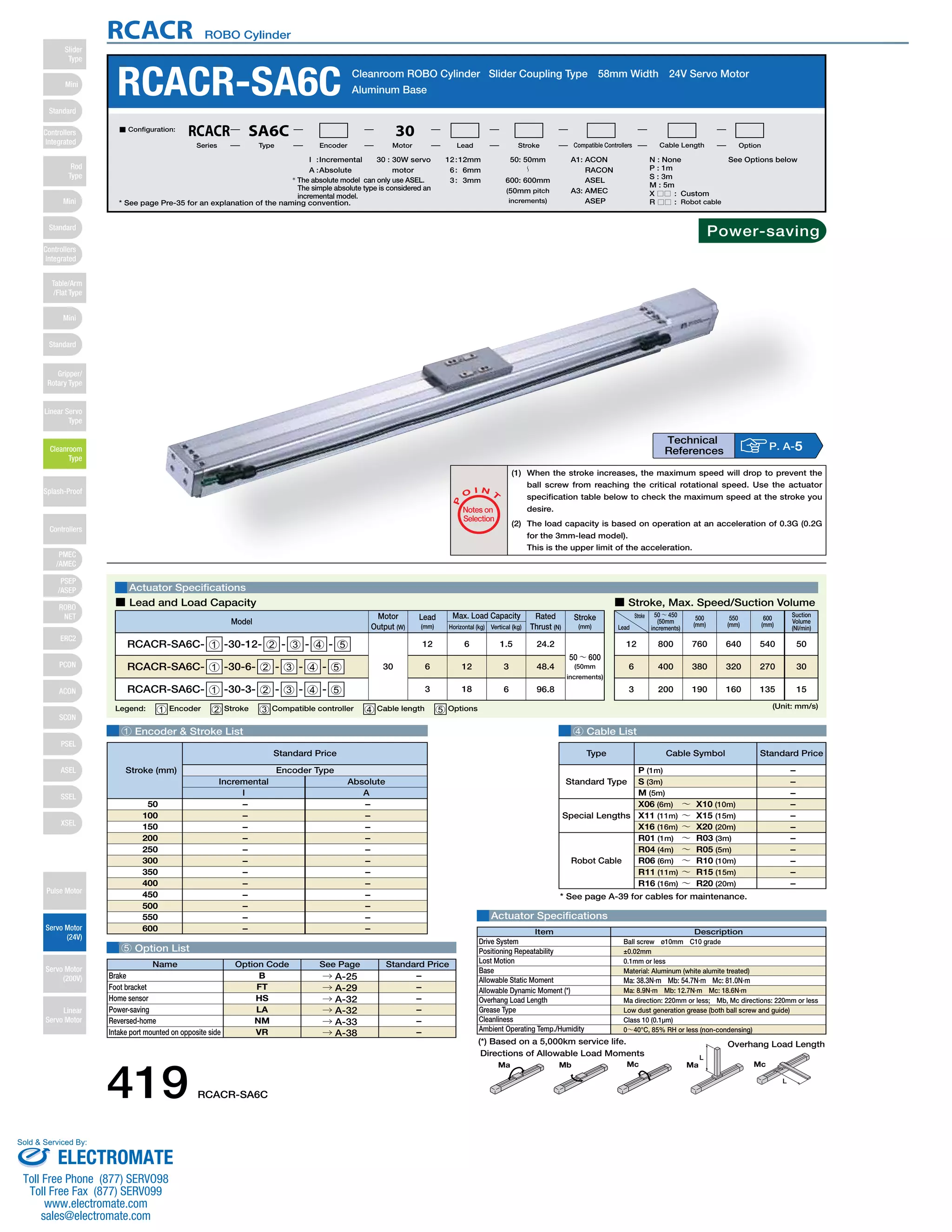
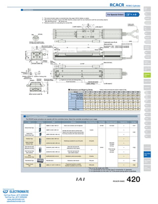

This document provides specifications for the RCACR-SA6C cleanroom ROBO cylinder. It includes details on the slider coupling type, servo motor, encoder, stroke length options, cable lengths, load capacity, dimensions, weight and compatible controllers. Compatible controllers include the ASEL, ASEP, ACON and RACON models. The document also provides notes on actuator selection and specifications.