NCIT civil Syllabus 2013-2014
•Download as DOCX, PDF•
0 likes•58 views

Structural mechanics

Recommended
Recommended
More Related Content
What's hot
What's hot (18)
Similar to NCIT civil Syllabus 2013-2014
Similar to NCIT civil Syllabus 2013-2014 (20)
More from LAKSHITHA RAJAPAKSHA
More from LAKSHITHA RAJAPAKSHA (20)
Recently uploaded
Recently uploaded (20)
NCIT civil Syllabus 2013-2014
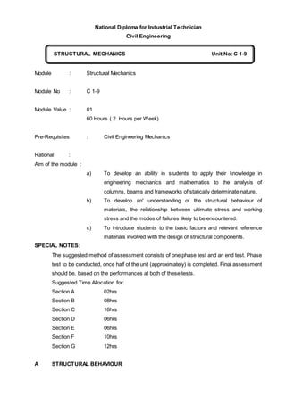
- 1. National Diploma for Industrial Technician Civil Engineering Module : Structural Mechanics Module No : C 1-9 Module Value : 01 60 Hours ( 2 Hours per Week) Pre-Requisites : Civil Engineering Mechanics Rational : Aim of the module : a) To develop an ability in students to apply their knowledge in engineering mechanics and mathematics to the analysis of columns, beams and frameworks of statically determinate nature. b) To develop an' understanding of the structural behaviour of materials, the relationship between ultimate stress and working stress and the modes of failures likely to be encountered. c) To introduce students to the basic factors and relevant reference materials involved with the design of structural components. SPECIAL NOTES: The suggested method of assessment consists of one phase test and an end test. Phase test to be conducted, once half of the unit (approximately) is completed. Final assessment should be, based on the performances at both of these tests. Suggested Time Allocation for: Section A 02hrs Section B 08hrs Section C 16hrs Section D 06hrs Section E 06hrs Section F 10hrs Section G 12hrs A STRUCTURAL BEHAVIOUR STRUCTURAL MECHANICS Unit No: C 1-9 C
- 2. 1. Develop an understanding of the various forms of structure and of the various modes of failure encountered in these structures. 1.1 Explain the basic concept of a structure in relation to force transmission and the principles of internal and external equilibrium. 1.2 Differentiate between the different modes of failure of simple 'structures and components (Tension, compression, Torsion, :Bending and shear.) 1.3 Identify configuration of loading which could induce internal structural effects in relation to: a) Horizontal simply supported beam. b) Horizontal straight cantilever. c) Vertical straight column d) Three hinged arch. e) Simple braced girder in vertical plane. 1.4 Sketch the deflected form under load for more complex structure, a) Propped cantilever. b) Fixed beams. , c) Continuous beams. d) Portal frames (no sway and with sway) B ENGINEERING PROPERTIES OF MATERIAL 2. Develop an understanding on the engineering' properties of materials which has a greater influence on the design of structural components. 2.1 Define the terms, "stress" and "strain". 2.2 Differentiate between elastic and plastic behaviour of materials under the direct action: of external loads. 2.3 Describe the behaviour or mild steel under the action of direct .tensile force. 2.4 Sketch the "stress-strain" diagram for the case is 2.3 and describe the diagram is relation to the important points and features:- Yield point, limit of proportionality, modulus of elasticity, ultimate stress, breaking point. 2.5 State Hookers law. 2.6 Define "factor of safety". 2.7 Explain different. types of factors of safety and their relevant importance in the process of structural design. 2.8 : Explain the behaviour of a compound bar subject to an axial force with relevance to stress distribution. 2.9 Solve simple problems associated with compound bars subject to axial force.
- 3. C. BENDING MOMENT AND SHEARING FORCES 3. Develop an understanding; on the structural changes taking place under static working loads and ability to compute these in numerical value for use in structural design. 3.1 Describe various types of loading, encountered in civil engineering i) Concentrated load ii) Uniformly distributed load iii) Triangularly distributed load 3.2 Describe effects taking place in a cross-section of a beam due to the action of an external load on the beam. 3.3 Define "Bending moment" and "Shearing force". 3.4 Compute bending moment and shearing force at a section of a beam under a given combination of loading;. 3.5 Draw bending moment diagrams and shearing force diagrams for beams under given combination of loading for the following simple cases; a) Cantilever beam b) Beam simply supported at ends. c) Over hanging beams. 3.6 Define the "Point of Contra flexure" in relation to the bending moment diagram for an over hanging beam. 3.7 Derive equations to express the relationship existing between load, bending moment and shearing force. D BENDING STRESSES 4. Develop an understanding on the bending stress distribution across a section of a loaded beam and the relation of other design factors. 4.1 Explain using a simple case of loading on a simple beam, how bending produces compression and tension across the depth of a beam, and that a neutral axis is produced. 4.2 Proves using area-moments, that the position of neutral axes of a section are dependent on its shape. 4.3 Calculate second moments of area about the neutral axes of various X-sections and relate them to the "stiffness" of the section. 4.4 Determine the section modulus about major axes of various types of cross sections encountered in structural engineering. 4.5 Relate section and material properties to resistance to deflection and bending and prove the theory of bending in the form
- 4. M /I = f/y = E/R 5. Relate bending moment data of a beam for a given condition and knowledge on the theory of bending to determine safe loading or beam sizes required for given allowable working stresses. 5.1 Calculate and plot bending stress distribution for rectangular, I and T sections subject to given load conditions. 5.2 Using techniques developed for determining bending moment values and determining' section, determine either safe loading or beam size requirement. 5.3 Consider elastic bending theory, defining modular ratio and derive relationship for stresses in members composed of two materials. 5.4 Solve simple problems on flitch beams for sizing component member or for determining allowable loading. E. COLUMNS AND WALL 06. Explain the relationship of shape, length and end restraint to the load carrying capacity of axially loaded columns and walls, Calculate safe loads or areas required for "short" column. 6.1 Explain the relationship of effective length of columns to fixity conditions. 6.2 Explain the concept of "slenderness ratio" for column and struts classifying "short" and "long" columns for various materials. 6.3 Explain the effect of "slenderness ratio" values on permissible axial compressive stresses for concrete, steel and timber columns. 6.4 Determine either safe loading or column size requirements for short columns in plain and reinforced concrete structural steel and structural timber subject to axial load. F. Beam Analysis 7.1 Apply double integration method to calculate maximum deflection of beams under given loading arrangements 7.2 State the advantage in using macaulay’s method to determine slope and deflection in beams subjected to a numbers of a beam 7.3 Use macaulay’s method to determine slope and deflection in beams subjected to a numbers of beams under given loading arrangement G FRAMED STRUCTURES 08. Develop understanding on framework analysis either by. graphical or semi graphical methods. . 8-1 List the assumptions made in the analysis of pin-jointed frameworks.
- 5. 8.2 Explain the conditions required for a statically determinate framed structure 8.3 Determine the nature and magnitude of forces in members of a pin-jointed framework, subject to combined wind and dead loading by graphical method. 8.4 Determine the internal forces ,in members of a framework, by calculating the reactions, sketching the force diagram and applying trigonometric properties to establish the magnitude of the forces. 9 Demonstrate an understanding of the concepts of resolution of forces and method of sections and analyse statically determinate framework. 9.1 Explain the concepts of "resolution of forces" and "method of sections" based on conditions for equilibrium showing how they can be applied to the analysis of pin- jointed frameworks. 9.2 Analyse statically determinate frameworks by resolution forces technique. 9-3 Analyse statically determinate frameworks by method of sections techniques.