DSM Based low oversampling using SDR transmitter

The oversampling recruitment is a limiting factor in high frequency application such as software defined radio. This project is a high frequency processing and low oversampling ratio. A single bit semi parallel processing is proposed in this paper. Using this single bit PDSM Architecture, high speed, high complexity computations are executed in parallel. The single bit DSM is to build an RF transmitter that includes a one bit quantifier with two level switching power amplifier for high linearity and high efficiency. Performance analysis by using the MATLAB simulations by reducing the oversampling ratio by same signal to noise ratio. The DSM implemented on field programmable gate array and using a signal code division multiple access signal. This project will give bandwidth of the low oversampled signal increased four times without increasing frequency. Finally they can be achieved signal to noise ratio is very low and also oversampling ratio is small.
![INTERNATIONAL JOURNAL FOR TRENDS IN ENGINEERING & TECHNOLOGY
VOLUME 5 ISSUE 1 – MAY 2015 - ISSN: 2349 - 9303
13
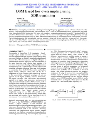
2. BLOCK DIAGRAM OF DSM
Fig 2: Block diagram of D
Fig:2 block diagram DSM
3.EXISTING SYSTEM
Several research works have utilized the concept of multi-
rate signal processing to reduce the oversampling ratio. A
Hadamard transform was used [10] [11] to decompose the
input spectrum into several sub-bands, which were then
applied to separate DSMs, whose outputs were subsequently
recombined. This work used two DSMs per output bit, which
is inefficient in terms of the die area when implemented using
radio frequency integrated circuits (RFIC) technology. The
structure is related to that of an M-path digital filter [ll]. On
each channel, the analog input sequence z[n] is modulated by
an analog f l sequence w,[n], AC modulated, decimation
filtered, and modulated by a digital *1 sequence uT[n]. The
outputs of the M channels are summed to produce the
IIACADC output y[n]. The part of the IIACADC that contains
the analog modulators and the AC modulator is referred to as
the 17nC modulator. The part of the IIACADC that includes
the decimation filters, digital modulators, and the channel
summers is referred to as the decoder. The N(z). the output of
the oversampling IIACADC can be viewed as the sum of an
overall signal component and an overall quantization error
component.An area-efficient architecture was developed
by combining multiple DSMs in parallel, along with
analog preprocessing of the input signal and digital post-
processing of the output signals. By using interconnected
modulators working in parallel with each running at the same
clock, a new Parallel processing DSM (PDSM) was
proposed. A Time Interleaved Sigma-Delta architecture was
used in to increase bandwidth of the converter with a lower
hardware complexity.
Fig:3 The oversampling ∏∆∑A/D converter
architecture(Hadamard transform)](data:image/gif;base64,R0lGODlhAQABAIAAAAAAAP///yH5BAEAAAAALAAAAAABAAEAAAIBRAA7)
Recommended
Recommended
More Related Content
What's hot
What's hot (20)
Viewers also liked
Similar to DSM Based low oversampling using SDR transmitter
Similar to DSM Based low oversampling using SDR transmitter (20)
More from IJTET Journal
More from IJTET Journal (20)
Recently uploaded
Recently uploaded (20)
DSM Based low oversampling using SDR transmitter
- 1. INTERNATIONAL JOURNAL FOR TRENDS IN ENGINEERING & TECHNOLOGY VOLUME 5 ISSUE 1 – MAY 2015 - ISSN: 2349 - 9303 12 DSM Based low oversampling using SDR transmitter Saranya.R Mr.B.Arun M.E., Me (Vlsi Design) Assistant Pofessor, Department Of Ece, Department Of Ece, Vandayar Engineering College, Vandayar Engineering College, Saranya2266ms@gmail.com er.arunbala@gmail.com Abstract:The oversampling recruitment is a limiting factor in high frequency application such as software defined radio. This project is a high frequency processing and low oversampling ratio. A single bit semi parallel processing is proposed in this paper. Using this single bit PDSM Architecture, high speed, high complexity computations are executed in parallel. The single bit DSM is to build an RF transmitter that includes a one bit quantifier with two level switching power amplifier for high linearity and high efficiency. Performance analysis by using the MATLAB simulations by reducing the oversampling ratio by same signal to noise ratio. The DSM implemented on field programmable gate array and using a signal code division multiple access signal. This project will give bandwidth of the low oversampled signal increased four times without increasing frequency. Finally they can be achieved signal to noise ratio is very low and also oversampling ratio is small. Keywords— Delta sigma modulator, PDSM, SDR, oversampling. —————————— —————————— I.INTRODUCTION Oversampling is Sigma-Delta (S-D) modulation based analog-to digital (A/D) conversion technology is a cost effective alternative for high resolution (greater than 12 bits) converters which can be ultimately integrated on digital signal processor ICs. The increasing use of digital techniques in communication and audio application has also contributed to the recent interesting cost effective high precision A/D converters. A requirement of analog-to-digital (A/D) interfaces is compatibility with VLSI technology, in order to provide for monolithic integration of both the analog and digital sections on a single die. Since the S-D A/D converters are based on digital filtering techniques, almost 90% of the die is implemented in digital circuitry which enhances the prospect of The compatibility. Additional advantages of such an approach include higher reliability, increased functionality, and reduced chip cost. Those characteristics are commonly required in the digital signal processing environment of today. Conventional high-resolution A/D converters, such as successive approximation and flash type converters, operating at the Nyquist rate(sampling frequency approximately equal to twice the maximum frequency in the input signal), often do not make use of exceptionally high speeds achieved with a scaled VLSI technology. These Nyquist samplers require a complicated analog low pass filter (often called an anti- aliasing filter) to limit the maximum frequency input to A/D, and sample-and hold circuitry. On the other hand, S-D A/D converters use a low resolution A/D converter (1-bit quantizer), noise shaping, and a very high oversampling rate (64 times for the DSP56ADC16). OVERSAMPLING has become a popular technique for data conversion. The outstanding linearity of delta-sigma modulators (DSMs) is the main reason for popularity of these modulators in modern electronic components such as data converters , frequency synthesizers, and switched-mode power supplies. linearity comes at the cost of a large oversampling ratio and, therefore, need for high-speed processing. The oversampling requirement in a DSM discourages its employment in today’s compute- intensive applications, such as software defined radio (SDR) systems..Software-Defined Radio (SDR) refers to the technology wherein software modules running on a generic hardware platform consisting of DSPs and general purpose microprocessors are used to implement radio functions such as generation of transmitted signal (modulation) at transmitter and tuning/detection of received radio signal (demodulation) at receiver. By using the proposed low-oversampling DSM, envelope signals in wireless applications, e.g., orthogonal frequency-division multiplexing (OFDM) and code division multiple access (CDMA), can be modulated to two-level signals. These signals can then be amplified with a switch- mode power By using the proposed low-oversampling DSM, envelope signals in wireless applications, e.g., orthogonal frequency-division multiplexing (OFDM) and code division multiple access (CDMA), multiple access (CDMA), can be modulated to two- level signals. These signals can then be amplified with a switch-mode power amplifier (PA.)
- 2. INTERNATIONAL JOURNAL FOR TRENDS IN ENGINEERING & TECHNOLOGY VOLUME 5 ISSUE 1 – MAY 2015 - ISSN: 2349 - 9303 13 2. BLOCK DIAGRAM OF DSM Fig 2: Block diagram of D Fig:2 block diagram DSM 3.EXISTING SYSTEM Several research works have utilized the concept of multi- rate signal processing to reduce the oversampling ratio. A Hadamard transform was used [10] [11] to decompose the input spectrum into several sub-bands, which were then applied to separate DSMs, whose outputs were subsequently recombined. This work used two DSMs per output bit, which is inefficient in terms of the die area when implemented using radio frequency integrated circuits (RFIC) technology. The structure is related to that of an M-path digital filter [ll]. On each channel, the analog input sequence z[n] is modulated by an analog f l sequence w,[n], AC modulated, decimation filtered, and modulated by a digital *1 sequence uT[n]. The outputs of the M channels are summed to produce the IIACADC output y[n]. The part of the IIACADC that contains the analog modulators and the AC modulator is referred to as the 17nC modulator. The part of the IIACADC that includes the decimation filters, digital modulators, and the channel summers is referred to as the decoder. The N(z). the output of the oversampling IIACADC can be viewed as the sum of an overall signal component and an overall quantization error component.An area-efficient architecture was developed by combining multiple DSMs in parallel, along with analog preprocessing of the input signal and digital post- processing of the output signals. By using interconnected modulators working in parallel with each running at the same clock, a new Parallel processing DSM (PDSM) was proposed. A Time Interleaved Sigma-Delta architecture was used in to increase bandwidth of the converter with a lower hardware complexity. Fig:3 The oversampling ∏∆∑A/D converter architecture(Hadamard transform)
- 3. INTERNATIONAL JOURNAL FOR TRENDS IN ENGINEERING & TECHNOLOGY VOLUME 5 ISSUE 1 – MAY 2015 - ISSN: 2349 - 9303 14 4. PROPOSED SYSTEM In this paper, an alternative approach, also based on parallel processing, is described. Here, however, multiple DSMs are not used. The proposed PDSM implements combined and simplified processing steps for n sequential clocks of a regular DSM (n closed loop computations.) A PDSM that combines n closed loops generates n bits per clock cycle. In fact the highest sampling frequency of the proposed PDSM is now shifted to one multiplexer, which is the same as the sampling frequency of the traditional single-bit DSM. The other processing element of PDSM work n times slower compared to traditional bit DSM The other processing element of PDSM work n times slower compared to traditional single-bit DSM. Fig 4:Digital implementation of PDSM For regular DSM, the sampling frequency of the input signal and clock frequency of the DSM are typically equal(the is value is fs for previous section.) Now, suppose the sampling frequency of the input signal is fs while the clock frequency of the DSM is fs, which may not be equal .Further more assume that f s > fs and, for simplicity of analysis, fs/fs is a positive integer value, N. The architecture is an extension of the third- order and four-unrolled PDSM shown in Fig. 5. It shows that N processor elements calculate N outputs in parallel. One processor calculates the states of the registers for the cycle N+1. The frequency of input sampling and for processing elements is fs. The PDSM output rate, which is equivalent to the PDSM throughput and output multiplexer selection frequency, is f s. f s can be called the effective frequency of PDSM, which considers parallel processing. The first part is dependent on the signal values of a2, a5, a7 and x at time n and can be processed at time n. The second part depends on y[n], which is processed by PE1, and its process is started at time n. The second part is a two-level value, and its two possibilities can be pre-calculated and stored in two registers. multiplexed from the two pre-calculated values available in the registers. is to make an or S can be driven with the two-level output of PDSM. The calculation of ya(i) requires y(i-1) from the last ya calculation. depicts a hardware implementation of a PDSM, based on (14) to (18). The Once y[n] is ready, the second part is multiplexed from the two pre- calculated values available in the registers. is to make an RF transmitter which includes a one-bit quantizer delta sigma and two-level switching power amplifier, which results in a high linearity. One of the most favorable applications of the proposed single-bit PDSM is to make an RF transmitter which includes a one-bit quantizer delta sigma and two-level switching power amplifier, which results in a high efficiency. Fig 5 Typical implementation of PDSM The main advantage of PDSM is to achieve higher SNR output signal using lower processing frequency compared to a regular DSM. One of the most favorable applications of the proposed single-bit PDSM is to make an RF transmitter which includes a one-bit quantizer delta sigma and two-level switching power amplifier, which results in a high efficiency and high linear transmitter. A two -level switching Power Amplifier Class D, E, F, F-1 or S can be driven with the two- level output of PDSM. The unrolling factor of the implemented PDSM was selected to be four. The PDSM and DSM were fed by CDMA signals with bandwidths of 1600 kHz and 400 kHz, respectively. The clock frequencies (sampling frequency) of the DSM and PDSM were 25 MHz. As shown in Fig. 14, with the help of parallel processing, the PDSM allows for an increase of the modulation bandwidth by a factor of 4 compared to DSM, while maintaining a comparable noise shaping performance. The power consumption of power amplifier in a PDSM based transmitter is of the order of 10 Watt.
- 4. INTERNATIONAL JOURNAL FOR TRENDS IN ENGINEERING & TECHNOLOGY VOLUME 5 ISSUE 1 – MAY 2015 - ISSN: 2349 - 9303 15 Therefore power consumption of PDSM is negligible compared to total power consumption of the transmitter. The multi-stage noise shaping (MASH) structure is also an alternative delta sigma structure which is simple for implementation and it isunconditionally stable. 5. OUTPUT Fig 6 :Transmit signal with noise Fig 7: Transmitting signal with high SNR Fig 8: Filter using reduced noise Fig 9: Reduced SNR
- 5. INTERNATIONAL JOURNAL FOR TRENDS IN ENGINEERING & TECHNOLOGY VOLUME 5 ISSUE 1 – MAY 2015 - ISSN: 2349 - 9303 16 Fig 10: Bandwidth CONCLUSION The delta-sigma modulation with a smaller oversampling rate. We proposed architecture uses the concept of parallel processing to achieve the effect of oversampling without the need for a high sampling frequency. The proposed structure has been validated through MATLAB simulation. Simulation results show that for a DSM with OSR = 256, the proposed structure is able to fold the required OSR 16 times while maintaining the same signal to noise (SNR) ratio. Increase the bandwidth of output signal four times without increasing the processing frequency. REFERENCES [1] Y. Wang, ―A class-S RF amplifier architecture with envelope delta-sigma modulation,‖ IEEE Radio and Wireless Conference, pp. 177-179, 2002. [2] F. M. Ghannouchi, S. Hatami, P. Aflaki, M. Helaoui, and F. M. Ghannouchi, "Multistandard GHz Wireless RF Transmitter Using a Delta-Sigma Modulator. [3] X. Wu, V. A. Chouliaras, J. L. Nunez and R. M. Goodall, "A novel ΔΣ control system processor and its VLSI implementation," IEEE Transactions on Very Large Scale Integration (VLSI) Systems, vol. 16, no. 3, March 2008, pp. 217-228. [4] D. Yang, F. F. Dai, W. Ni, Y. Shi, and R. C. Jaeger, ―Delta-Sigma modulation for direct digital frequency synthesis,‖ IEEE Transactions Very Large Scale Integrated (VLSI) Systems, vol. 17, no. 6, pp. 793–802, Jun. 2009. [5] M. Helaoui, S. Hatami, R. Negra, and F.M. Ghannouchi, ―A Novel Architecture of Delta-Sigma Modulator Enabling All-Digital Multiband Multistandard RF Transmitters Design,‖ IEEE Transactions Circuits and Systems II, vol. 55, no. 11, pp. 1129-1133, Nov. 2008. [6] S. Hatami, M. Helaoui, R. Negra, and F.M. Ghannouchi, ―Multiband Multistandard Delta-Sigma-based RF Transmitters,‖ Software Defined Radio Technical Conference (SDR'07 Tech Conf), Denver, CO, Nov. 2007. [7] J.S. Keyzer, J.M. Hinrichs, A.G. Metzger, M. Iwamoto, I. Galton, and P.M. Asbeck, ―Digital generation of RF signals for wireless communications with band-pass delta-sigma modulation,‖ IEEE MTT-S International Microwave Symposium Digest, vol. 3, pp. 2127-2130, 2001. [8] J. Rode, J. Hinrichs, and P. Asbeck, ―Transmitter architecture using digital generation of RF signals,‖ IEEE Radio and Wireless Conference, 2003, pp. 245-248. [9] R. Schreier and G.C. Temes, Understanding Delta-Sigma Data Convertors, IEEE Press, Piscataway NJ, 2005. [10] I. Galton, H.T. Jensen, ―Delta-Sigma modulator based A/D conversion without oversampling,‖ IEEE Transactions Circuits and Systems II, vol. 42, no. 12 [11] I. Galton, H.T. Jensen, ―Delta-Sigma modulator based A/D conversion without oversampling,‖ IEEE Transactions Circuits and Systems II, vol. 42, no. 12, 1995.