SlideShare a Scribd company logo
1 of 13
Download to read offline
Alexandre A. Motta Int. Journal of Engineering Research and Applications www.ijera.com
ISSN: 2248-9622, Vol. 5, Issue 9, (Part - 1) September 2015, pp.07-19
www.ijera.com 7 | P a g e
An Evolutionary Method for Kinetic Energy Ammunition
Optimization
Alexandre A. Motta, Nelson F. F. Ebecken
NTT/COPPE/Universidade Federal do Rio de Janeiro
Cidade Universitária, CT Bloco B Sala 100
Caixa Postal: 68506
Rio de Janeiro, RJ, Brazil - 21945-970
Abstract
A research is being carried on to optimise long rod penetrators used in kinetic energy munitions. Kinetic energy
munitions performance can be measured by the penetration achieved in a normal impact on a semi-infinite steel
plate (rolled homogeneous armour, RHA). For a reference target (fixed characteristics and distance)
performance will depend of the properties and characteristics of the penetrator and the propellant charge,
assuming that no changes will be made in the firing gun. The properties and characteristics of the propellant
charge and of the penetrator will dictate the terminal velocity and how the penetrator will interact with the
target. This is a well known problem with several proved models available in the literature. However, no method
has been proposed to find an optimal configuration. In the present work, the penetration achieved with a
particular configuration (set of parameters) is combined with relevant penalisations thus providing its fitness for
ranking by the Genetic Algorithm code in the search for an optimal configuration.
Keywords: Kinetic Energy Ammunition, Long Rod Penetrator, Optimization, Genetic Algorithms, Impact
I. INTRODUCTION
“Long rod penetrators are modern equivalents of
the cannonball, intended to pierce a target by
depositing large amounts of kinetic energy in a
concentrated region” (Wright, 1983).
Kinetic energy (KE) ammunition is mainly used
to attack armour. The long rod penetrator is the
option of choice to defeat heavy tanks by tanks. The
theory for the one-dimensional penetration of semi-
finite targets by long rods is based in the work from
Tate (1967, 1969) and Alekseevskii (1966). It
describes the interaction between the penetrator and
the target and attempts to predict the characteristics
of the resulting crater in the last. The literature in this
subject is vast and many authors have provided
valuable contributions to it, like the overviews made
by Zook et al. (1992), Goldsmith (1999) and Orphal
(2006), the survey carried on by Wright (1983) and
the database produced by Anderson et al. (1992).
Other authors have also carried on analytical,
numerical and experimental studies and proposed
extensions or modifications to the Alekseevskii-Tate
model, like Rosenberg (1990), Jones et al. (1987),
Wang and Jones (1996), Grace (1993), Walker et al.
(1995), Rubin and Yarin (2002), Walters (1991),
Seglets and Walters (2003), Walker (2001), Lan and
Wen (2010) and Wen et al. (2010, 2011).
The strike velocity determines the regime at
which the interaction between long rods and rolled
homogenous armour (RHA). Penetration is governed
by plastic deformation mechanism for strike
velocities up to 1,150m/s (Bennett, 1998 and
Longdon, 1987) and hydrodynamic behaviour occurs
at strike velocities greater than several km/s, like in
shaped charge munitions (Doig, 1998). Typical strike
velocities for long rod munitions are in the range
between 1,500m/s and 1,700m/s and both
mechanisms are observed (Bennett, 1998). Designers
seek to achieve the maximum possible strike velocity
upon impact, combined with long penetrators made
of materials with higher density than the expected
target. This is supported by experimental work
(Hohler & Stilp, 1997 and 1978).
Bennett (1998), however, points out that
although “first thoughts suggest that continual
improvements in penetration by means of higher
strike velocities with ever longer and more dense
penetrators might be relatively easy to achieve”,
“more careful thought shows that these features
interact with each other, and with other important
factors such as the internal and external ballistics, the
forces on both the ammunition and the gun, and the
ammunition stowage and handling”. The author
describes the consequences of increasing the long rod
length, keeping all other parameters constant. Among
others, an increased surface area will increase the
drag and reduce the strike velocity, a longer, heavier
sabot will be required for in-bore stability (with
greater parasite mass) and an increased higher peak
pressure, due to the higher inertia of the heavier shot,
will be observed resulting in higher stresses in the
barrel, not to mention the reduction in muzzle
RESEARCH ARTICLE OPEN ACCESS
Alexandre A. Motta Int. Journal of Engineering Research and Applications www.ijera.com
ISSN: 2248-9622, Vol. 5, Issue 9, (Part - 1) September 2015, pp.07-19
www.ijera.com 8 | P a g e
velocity.
The models for interior, exterior and terminal
ballistics of long rods presented by Bennett (1998)
were selected for use in the present work to estimate
the performance achieved using configurations
described by a set of parameters. These models are
summarized in sections 2.1, 2.2 and 2.3. For
consistency, the parameters herein are limited to:
penetrator diameter, penetrator length-diameter ratio,
penetrator density, sabot-penetrator length ratio,
sabot mean diameter-bore diameter ratio, sabot
density, charge mass, charge force constant, charge α,
charge β, charge ballistic size, charge form function
and propellant shape. Gun chamber volume and shot
travel were not considered because they are related to
the gun, not the ammunition. Each set of parameters
(variables) constitutes an individual in the Genetic
Algorithm (GA) application. Fitness is measured by
the penetration achieved in a target (RHA) positioned
1,000m away from the muzzle.
The machine used in the present development
until the submission of the present article was a
“domestic” PC (processor Intel(R) Core(TM) i5-
2500K, 4GB RAM, Windows 7 Professional). All
implementation was carried on using Fortran.
II. BALLISTIC MODELS
2.1 Interior Ballistics Model
Bennett (1998) proposed the use of the lumped
parameter model as presented in Longdon (1987).
The behaviour of the gas during the combustion and
its expansion processes are described in terms of the
average gas properties and rates of change.
According to the author, this assumption is
particularly adequate near the muzzle and therefore
suitable to predict the muzzle velocity and the peak
pressure. This model calculates the muzzle velocity,
allowing the determination of the shot trajectory and
the strike velocity. All names and subscripts used by
Bennett (1998) were kept for consistency.
Piobert‟s law governs the combustion of the
propellant and it is assumed that all surfaces burn
inwards at a constant burn rate. The ballistic grain
size D is measured as the shortest distance between
opposing sides and combustion ends when these sides
meet and D equals zero. The burning rate depends on
the ambient pressure and is defined by the fraction f
of D remaining at a time t:
D
β p
-
dt
df α
 , (1)
where α (the burning rate coefficient) and β (the
burning rate index) depend on the propellant.
The geometry of the propellant grain determines
the relationship between f and the mass fraction of
burnt propellant (z) through a semi-empirical
constant, the form function (c):
cf)- f) ((z  11 . (2)
The energy released during combustion of the
propellant charge can be evaluated according to:
μεqrugsp EEEEEEEE 
(3)
where:
Ep = energy released by the propellant charge
Es = shot KE
Eg = gas KE
Eu = unburnt propellant KE
Er = recoiling mass (gun) KE
Eq = gas residual heat
Eε = barrel strain energy
Eμ = shot friction
Typically, the strain energy of the gun is less
than 0.5 % of the total energy and can be neglected
(Longdon, 1987). The equations of motion for the
shot travelling inside the barrel can be written as:
dt
dx
v
) - R- P(PA
dt
dv
m iasb


(4)
where:
m = combined mass of the penetrator and the
sabot
v = shot velocity
x = shot displacement in the barrel
Ab = bore cross-section
Ps = shot base pressure
Pa = atmospheric pressure
Ri = resistance to motion (friction)
Fourth order Runge-Kutta integration was used
to calculate the muzzle velocity, the maximum
chamber pressure and the shot motion, allowing the
determination of the maximum nominal sabot shear
stress (NSSS  the first constraint in this application),
the maximum value achieved by the breech pressure
(the second constraint, assumed to be equal to Pb) and
the all-burnt position (AB, the last constraint). The
AB is the position in the bore the projectile is in the
instant that all propellant charge is burned.
2.2. Exterior Ballistics Model
For long rod penetrators, the distance between
leaving the gun and striking the target is generally no
more than 3,000m and therefore the trajectory lasts 2s
or less hence, the only factors that need to be
Alexandre A. Motta Int. Journal of Engineering Research and Applications www.ijera.com
ISSN: 2248-9622, Vol. 5, Issue 9, (Part - 1) September 2015, pp.07-19
www.ijera.com 9 | P a g e
considered are drag and gravity (Bennett, 1998). This
model allows the determination of the strike velocity,
required to determine the penetration in the target.
The drag force (FD) can be calculated as:
FXBSND FFFFFF  (5)
where:
FN = nose drag
FS = skin drag
FB = base drag
FX = excrescence drag
FF = fin drag
Drag forces are calculated using Eq. 6 (McCoy,
1999):
2
2
42
1
v)
πd
(CρF D , (6)
where:
CD = drag coefficient
d = penetrator diameter
v = penetrator velocity
ρ = air density
And the equations of motion for the projectile
become:
g( θ θ ) -- Fxm
( θ θ- Fxm
pDp
Dp
sin
cos
2
1




(7)
where:
mp = penetrator mass
x1 = horizontal displacement from the
muzzle
x2 = vertical displacement from the muzzle
ϴ = angle between the penetrator velocity
vector and the horizontal
2.3. Terminal Ballistics Model
Finally, the model adopted by Bennett (1998)
starts assuming hydrodynamic penetration, similarly
to the model presented by Held (1991) for shaped
charges.
After the initial contact, the velocity of the rear
of the penetrator is assumed to be constant, equal to
the strike velocity, v. As the penetration process
develops, the crater growth is assumed to happen at a
constant rate, u. Using Bernoulli, it is possible to
write:
22
uρ( v - u )ρ tp  , (8)
where:
ρp = penetrator density
ρt = target density
v = strike velocity
u = crater growth rate
It is also assumed that the crater stops growing
when the whole penetrator is eroded. Therefore:
u
P
v - u
L
 , (9)
where:
L = penetrator length
P = penetration depth
Rearranging Eq. 8 and 9, the penetration
equation can be obtained:
t
p
ρ
ρ
L
P
 , (10)
Since the strike velocity is below the lower limit
for pure hydrodynamic penetration, an
experimentally determined coefficient, k, is added to
Eq. 10:
t
p
ρ
ρ
k
L
P
 , (11)
Bennett (1998) proceeds providing a sample set
of data (presented in section 2.4) which was adopted
as reference.
2.4. Data and Limits
The data used by Bennett (1998) was used as
approximate central values for the minimum and
maximum values for each variable of the problem.
These values and the lower and upper limits for each
variable are presented in Table 1.
Alexandre A. Motta Int. Journal of Engineering Research and Applications www.ijera.com
ISSN: 2248-9622, Vol. 5, Issue 9, (Part - 1) September 2015, pp.07-19
www.ijera.com 10 | P a g e
Table 1: Data and limits for the variables and constraints in the application
Variable Bennett (1998) Minimum Maximum
penetrator diameter 0.025 m 0.020 m 0.030 m
penetrator length-diameter ratio 16.0 12.0 20.0
penetrator density 16,500 kg/m3
14,000 kg/m3
18,600 kg/m3
sabot-penetrator length ratio 0.760 0.500 0.850
sabot mean diam-bore diam ratio 0.500 0.500 0.850
sabot density 2,710 kg/m3
2,000 kg/m3
7,850 kg/m3
charge mass 6.700 kg 6.500 kg 7.200 kg
charge force constant 951,000 J/kg 940,000 J/kg 1,050,000 J/kg
charge α 1.680E-9 1.680E-9 1.680E-9
charge β 0.993 0.950 1.000
charge ballistic size 0.0015 m 0.0012 m 0.0018 m
charge form function 0.190 -0.050 0.200
propellant shape stick Stick
Constraint
NSSS 63 MPa N/A 100 MPa
Pb 462 MPa N/A 550 MPa
AB 33% 27% 35%
III. METHOD AND INITIAL RESULTS
3.1 The method
The choice for GA as optimization method
follows from the problem characteristics: it is a
multi-variable problem with conflicting objectives
and a variety of constraints. The implementation was
validated using the examples provided in Bennett
(1998).
In GA, a random population is generated and a
value of fitness is attributed to each individual.
Individuals in a given population are ranked
according to this value and elitism, cross-over and
mutation operations can be applied producing a new
generation. This generation will be ranked as the first
and new operations may be applied (Goldberg, 1989
and Motta, 2004). This is repeated successively until
a criterion is met  in the present work a previously
selected number of generations.
The strategy used by Motta & Ebecken (2006)
was selected for the present work: each set of
parameters (or variables) were arranged in an array,
constituting an individual, a set of individuals
constituting a generation. The main difference is that
binary codification was only used to perform cross-
over and mutation operations. All other operations
were performed in decimal, double precision
codification. Similarly to this work, random mono-
point cross-over and mutation operations were
implemented in non-elite members of the population.
An initial population of individuals with random
attributes (valid variable values) is generated and
their fitness determined, after which they are ranked
and the non-elite members submitted to cross-over
and mutation operations (according to the respective
probabilities of occurrence), resulting in a new
generation. This process is repeated until a criterion
is reached (in this work, a pre-selected number of
generations).
The process to determine the fitness of an
individual  or a configuration, a set of variables,
followed the ballistic model described in item 2: the
muzzle velocity was calculated using the interior
ballistics model, feeding the exterior ballistics model
to determine the strike velocity which was used by
the terminal ballistics model to determine the
penetration achieved by that configuration.
The constraints AB, NSSS and Pb calculated in
the interior ballistics model and other characteristics
such as penetrator length or charge mass can be used
to penalize a configuration. Initially, individuals with
values outside the limits shown in Table 1 were given
nil fitness but this strategy proved to lead to results
that although reasonably similar and improved when
compared to state-of-art ammunition performance
lacked convergence in a strict sense. Therefore, other
penalisation methods are being tested as discussed in
item 3.2.
3.2 Sensitivity
A sensitivity analyses was conducted to provide
insight with respect to the impact of small variations
in the values of the variables on performance. Charge
mass variation was selected to illustrate this in the
present work. Simulations were run with fixed values
for all variables but the charge mass (all in the valid
range) as shown in Table 2. The results are presented
in Table 3. The application returned zero fitness for
some values but it was not continue. It can be
observed that variations in the charge mass between
7.01043 kg and 7.01473 kg  only 430 g, produce
and unexpected result. The non-zero values in Table
3 are plotted in Fig. 1. These results are reproducible.
This model is highly sensitive to small variations
in the parameters and this impacts convergence, as
Alexandre A. Motta Int. Journal of Engineering Research and Applications www.ijera.com
ISSN: 2248-9622, Vol. 5, Issue 9, (Part - 1) September 2015, pp.07-19
www.ijera.com 11 | P a g e
shown in item 3.3.
Table 2: Parameters for sensitiveness analysis
Variable Value Minimum Maximum
penetrator diameter 0.02870 m 0.020 m 0.030 m
penetrator length-diameter ratio 19.75 12.0 20.0
penetrator density 18202 kg/m3
14000 kg/m3
18600 kg/m3
sabot-penetrator length ratio 0.600 0.500 0.850
sabot mean diam-bore diam ratio 0.540 0.500 0.850
sabot density 2137.64 kg/m3
2000 kg/m3
7850 kg/m3
charge mass variable 6.500 kg 7.200 kg
charge force constant 1032460 J/kg 940000 J/kg 1050000 J/kg
charge α 1.6760E-09 1.680E-9 1.680E-9
charge β 0.995 0.950 1.000
charge ballistic size 1.70 E-3 m 1.20E-3 m 1.8E-3 m
charge form function 0.095 -0.050 0.200
propellant shape stick stick or grain
gun chamber volume 0.0078 m 0.007 m3
0.009 m3
shot travel 6.611 m 4.50 m 7.20 m
Table 3: Fitness according to the variation of the charge mass
Charge Mass (kg) Penetration (m)
7.01043 0.66063
7.01065 0.66068
7.01086 0.66073
7.01108 0.00000
7.01129 0.00000
7.01151 0.00000
7.01172 0.00000
7.01194 0.00000
7.01215 0.00000
7.01237 0.00000
7.01258 0.66114
7.01280 0.66074
7.01301 0.66079
7.01323 0.66084
7.01344 0.66089
7.01366 0.66095
7.01387 0.66100
7.01409 0.66105
7.01430 0.66110
7.01452 0.00000
7.01473 0.66120
Alexandre A. Motta Int. Journal of Engineering Research and Applications www.ijera.com
ISSN: 2248-9622, Vol. 5, Issue 9, (Part - 1) September 2015, pp.07-19
www.ijera.com 12 | P a g e
0.6605
0.6610
0.6615
7.01043
7.01065
7.01086
7.01108
7.01129
7.01151
7.01172
7.01194
7.01215
7.01237
7.01258
7.01280
7.01301
7.01323
7.01344
7.01366
7.01387
7.01409
7.01430
7.01452
7.01473
Penetration(m)
Charge Mass (kg)
SensitivityAnalyses
Fig. 1: Sensitivity analyses: fitness variation according to different charge masses
3.3 Convergence
In this work, convergence refers to the
generation in which the best fit individual (the set of
parameters that resulted in the highest penetration)
was found. After the implementation strategy was
resolved, it was decided to use a population with 400
individuals – it was not observed a direct correlation
between the size of the population and convergence
although populations with less than 100 individuals
were not tried. The rates of elitism, cross-over and
mutation also seemed to have little impact in
convergence.
Table 4 shows five results obtained after 10,000
generations with 2% elitism, 70% cross-over rate and
90% mutation rate. One may argue that these rates
are exaggerated, but virtually dozen executions with
varied rates showed no direct correlation between
them and convergence or the results obtained.
Table 4: Results obtained after 10,000 generations
Elitism 2%
Cross-over rate 70%
Mutation Rate 90%
Generations 10000
Execution #: 1 2 3 4 5
Highest Fitness: 0.5177 0.5111 0.5076 0.5163 0.5205
Generation: 7268 5555 2053 6777 8384
Best fit indiv.:
Penetrator Diam 0.0203 0.0223 0.0228 0.0218 0.0223
Pen L-D Ratio 18.9196 19.6382 19.0821 19.3108 19.3809
Penetrator Dens 17748.150 15705.612 15541.733 16458.950 17455.637
Sabot L-Ratio 0.6587 0.5909 0.5527 0.6233 0.6341
Sabot Diam-Ratio 0.5328 0.5615 0.5251 0.5357 0.5079
Sabot Density 2349.428 2048.758 2324.745 2039.092 2115.995
Charge Mass 7.1599 6.8416 7.0982 6.9152 7.1960
Charge Force Constant 1.050E+06 1.045E+06 1.040E+06 1.025E+06 1.026E+06
Charge α 0.9983 0.9965 0.9910 0.9977 0.9969
Charge β 1.718E-09 1.567E-09 1.786E-09 1.794E-09 1.541E-09
Charge Ball. Size 0.0016 0.0014 0.0014 0.0015 0.0014
Charge Form Func 0.1015 0.1241 -0.0451 0.0254 -0.0456
Constraints:
AB 0.3214 0.3113 0.3045 0.2702 0.3165
NSSS 1.736E+07 1.693E+07 1.878E+07 1.666E+07 1.750E+07
Pb 1.158E+08 1.086E+08 1.142E+08 1.074E+08 1.142E+08
Convergence for the executions showed in Table
4 can be observed in Fig. 2. The results are very good
and above what is expected in practical terms for this
type of ammunition, but it is not considered that
convergence was achieved. It should be noted that a
logarithmic scale was used for the Generation axis
Alexandre A. Motta Int. Journal of Engineering Research and Applications www.ijera.com
ISSN: 2248-9622, Vol. 5, Issue 9, (Part - 1) September 2015, pp.07-19
www.ijera.com 13 | P a g e
(horizontal). Table 5 and Fig. 3 show the same
outputs for 30,000 generations without any
improvement in the convergence. Table 6 and Fig. 4
present the results using different cross-over rates and
Table 7 and Fig. 5 present the results using different
mutation rates (10,000 generations).
There are noticeable differences in the values of
most variables and clearly the method, as is, did not
achieve what is expected, a unique, reproducible
solution. Increasing the number of generations did
not produce any impact in the convergence.
0.350
0.450
0.550
1 10 100 1000 10000
Penetration(m)
Generation
Convergence
Exec. #1 Exec. #2 Exec. #3 Exec. #4 Exec. #5
Fig. 2: Convergence (penetration achieved) after 10,000 generations
Table 5: Results obtained after 30,000 generations
Elitism 2%
Cross-over rate 70%
Mutation Rate 90%
Generations 30000
Execution #: 1 2 3 4 5
Highest Fitness: 0.5187 0.5206 0.5117 0.5206 0.5180
Generation: 14959 7666 26695 28076 22069
Best fit indiv.:
Penetrator Diam 0.0222 0.0212 0.0204 0.0225 0.0212
Pen L-D Ratio 19.9960 19.7749 19.8852 19.6862 19.3110
Penetrator Dens 14852.957 17817.392 16355.482 16325.378 17694.685
Sabot L-Ratio 0.5688 0.6081 0.6338 0.7042 0.6546
Sabot Diam-Ratio 0.5550 0.5020 0.5679 0.5173 0.5079
Sabot Density 2210.531 2361.125 2197.778 2017.631 2055.335
Charge Mass 7.0600 7.1561 7.1919 7.1252 6.6124
Charge Force Const 1.045E+06 1.007E+06 1.042E+06 1.048E+06 1.047E+06
Charge α 0.9989 0.9928 0.9956 0.9830 0.9924
Charge β 1.772E-09 1.548E-09 1.561E-09 1.698E-09 1.558E-09
Charge Ball. Size 0.0017 0.0013 0.0014 0.0013 0.0012
Charge Form Funct 0.0567 0.0845 -0.0038 0.1582 0.1427
Constraints:
AB 0.3041 0.3401 0.3452 0.3473 0.2946
NSSS 1.713E+07 1.799E+07 1.698E+07 1.460E+07 1.676E+07
Pb 1.130E+08 1.110E+08 1.182E+08 1.135E+08 1.050E+08
Alexandre A. Motta Int. Journal of Engineering Research and Applications www.ijera.com
ISSN: 2248-9622, Vol. 5, Issue 9, (Part - 1) September 2015, pp.07-19
www.ijera.com 14 | P a g e
0.350
0.450
0.550
1 10 100 1000 10000
Penetration(m)
Generation
Convergence
Exec. #1 Exec. #2 Exec. #3 Exec. #4 Exec. #5
Fig. 3: Convergence (penetration achieved) after 30,000 generations
Table 6: Results obtained after 10,000 generations using different cross-over rates
Execution #: 1 2 3 4 5
Elitism 2%
Cross-over rate 40% 50% 60% 70% 80%
Mutation Rate 90%
Generations 10000
Highest Fitness: 0.5211 0.5209 0.5195 0.5060 0.5116
Generation: 1774 7195 6288 7707 3770
Best fit indiv.:
Penetrator Diam 0.0205 0.0229 0.0224 0.0202 0.0212
Pen L-D Ratio 19.3443 19.9995 19.9028 19.9048 19.1149
Penetrator Dens 17858.288 14360.685 15729.378 17897.276 17923.025
Sabot L-Ratio 0.6459 0.5269 0.5638 0.7234 0.6661
Sabot Diam-Ratio 0.5309 0.5370 0.6065 0.5759 0.5218
Sabot Density 2212.802 2232.409 2068.758 2158.166 2117.647
Charge Mass 7.1469 7.0328 7.1450 6.9197 7.0469
Charge Force Const 1.014E+06 1.044E+06 1.043E+06 1.047E+06 1.037E+06
Charge α 0.9923 0.9853 0.9849 0.9851 0.9940
Charge β 1.686E-09 1.724E-09 1.720E-09 1.781E-09 1.629E-09
Charge Ball. Size 0.0014 0.0012 0.0013 0.0013 0.0014
Charge Form Funct 0.1509 0.0520 0.0174 0.1493 0.0258
Constraints:
AB 0.3441 0.3179 0.3096 0.3161 0.3441
NSSS 17241404 18332357 17828085 14438789 17242462
Pb 111372340 112782270 113922250 109518160 113924370
Alexandre A. Motta Int. Journal of Engineering Research and Applications www.ijera.com
ISSN: 2248-9622, Vol. 5, Issue 9, (Part - 1) September 2015, pp.07-19
www.ijera.com 15 | P a g e
0.350
0.450
0.550
1 10 100 1000 10000
Penetration(m)
Generation
Convergence
TXC = 40% TXC = 50% TXC = 60% TXC = 70% TXC = 80%
Fig. 4: Convergence after 10,000 generations using different cross-over rates
Table 7: Results obtained after 10,000 generations using different mutation rates
Execution #: 1 2 3 4 5
Elitism 2%
Cross-over rate 50%
Mutation Rate 40% 50% 60% 70% 80%
Generations 10000
Highest Fitness: 0.5276 0.5151 0.5193 0.5277 0.5252
Generation: 3392 5747 8601 9743 7733
Best fit indiv.:
Penetrator Diam 0.0215 0.0208 0.0204 0.0206 0.0214
Pen L-D Ratio 19.8844 19.0818 19.0538 19.5370 19.9750
Penetrator Dens 16431.377 17454.163 18282.739 17792.577 17078.896
Sabot L-Ratio 0.6682 0.6437 0.6325 0.6188 0.5974
Sabot Diam-Ratio 0.5378 0.5110 0.5115 0.5309 0.5317
Sabot Density 2009.819 2267.297 2405.675 2271.450 2166.429
Charge Mass 7.0769 6.8986 7.0421 7.1705 7.0330
Charge Force Const 1.040E+06 1.022E+06 1.034E+06 1.025E+06 1.020E+06
Charge α 0.9954 0.9896 0.9993 0.9951 0.9863
Charge β 1.748E-09 1.677E-09 1.610E-09 1.550E-09 1.695E-09
Charge Ball. Size 0.0016 0.0012 0.0014 0.0013 0.0013
Charge Form Funct 0.1812 0.1128 0.0062 0.0401 0.1252
Constraints:
AB 0.3466 0.2813 0.2945 0.3211 0.3424
NSSS 15651065 16730535 18227144 18199768 17863689
Pb 112576340 106645640 112342570 113637770 110342740
Alexandre A. Motta Int. Journal of Engineering Research and Applications www.ijera.com
ISSN: 2248-9622, Vol. 5, Issue 9, (Part - 1) September 2015, pp.07-19
www.ijera.com 16 | P a g e
0.350
0.450
0.550
1 10 100 1000 10000
Penetration(m)
Generation
Convergence
TXM = 40% TXM = 50% TXM = 60% TXM = 70% TXM = 80%
Fig. 5: Convergence after 10,000 generations using different mutation rates
3.4 Other strategies to improve convergence
In order to improve convergence, different
penalisation strategies promoting smoother, gradual
reduction on fitness as the variables approach the
limits of the allowed intervals are implemented. Such
strategies were used by Motta & Ebecken (2006) and
account for less tangible aspects like loss of accuracy
as AB moves away from the centre of the allowed
interval, increased stowage space required for longer
rounds, cost etc. Figure 6 shows multipliers that can
be used to penalise the individuals according to the
constraints. The curve for AB is parametric of fourth
order and was designed to not heavily penalise
central values (with respect to the allowed range).
The other curves represent linear progressive
penalisation after a threshold is reached. These
implemented penalisations are for demonstration
purposes and specific rules must be developed for
individual cases.
0.00
0.20
0.40
0.60
0.80
1.00
1.20
-1.50 -1.00 -0.50 0.00 0.50 1.00 1.50
Multiplier
Value with respect to the mean value
Penalisationaccording to AB
0.00
0.20
0.40
0.60
0.80
1.00
1.20
0.0E+00 5.0E+07 1.0E+08
Multiplier
NSSS
Penalisationaccording to NSSS
0.0
0.2
0.4
0.6
0.8
1.0
1.2
0.E+00 1.E+08 2.E+08 3.E+08 4.E+08 5.E+08 6.E+08
Multiplier
Pb
Penalisationaccording to Pb
(a) (b) (c)
Fig. 6: Penalisations for AB (a), NSSS (b) and Pb (c)
Table 8 and Fig. 7 show the results and convergence evolution applying such constraint-related penalties. It
can be observed that this conservative approach leads to lower penetration values and that the most fit individual
may not be the one with highest penetration.
Alexandre A. Motta Int. Journal of Engineering Research and Applications www.ijera.com
ISSN: 2248-9622, Vol. 5, Issue 9, (Part - 1) September 2015, pp.07-19
www.ijera.com 17 | P a g e
Table 8: Results obtained using constraint-related penalisation
Execution #: 1 2 3 4 5
Elitism 2%
Cross-over rate 70%
Mutation Rate 90%
Generations 10000
Highest Fitness: 0.3665 0.3696 0.3788 0.3729 0.3757
Highest Penetration: 0.3920 0.3829 0.3868 0.3797 0.3873
Generation: 7687 3392 6174 391 4712
Best fit indiv.:
Penetrator Diam 0.0201 0.0208 0.0202 0.0201 0.0204
Pen L-D Ratio 19.9345 19.0921 19.8904 18.6665 19.9337
Penetrator Dens 17698.183 18069.224 18251.671 15333.106 17402.227
Sabot L-Ratio 0.8213 0.7625 0.7575 0.7652 0.7173
Sabot Diam-Ratio 0.5101 0.5049 0.5016 0.5051 0.5103
Sabot Density 2146.130 2089.920 2286.510 2091.233 2198.692
Charge Mass 7.1219 7.1595 7.1907 7.1768 7.1778
Charge Force Const 9.923E+05 1.007E+06 1.033E+06 1.032E+06 1.038E+06
Charge α 0.9733 0.9819 0.9888 0.9903 0.9887
Charge β 1.783E-09 1.693E-09 1.525E-09 1.732E-09 1.737E-09
Charge Ball. Size 0.0013 0.0014 0.0015 0.0016 0.0017
Charge Form Funct 0.1221 0.0153 -0.0158 -0.0359 0.0116
0.200
0.300
0.400
0.500
1 10 100 1000 10000
Penetration(m)
Generation
Convergence
Exec. #1 Exec. #2 Exec. #3 Exec. #4 Exec. #5
Fig. 7: Convergence applying constraint-related penalties
Analysts should pay attention to the fact that the
individual with higher penetration (performance) may
not be the best fit in the population and thoughtful
considerations might be necessary to assess whether
adequate penalisation criteria are in place.
IV. CONCLUSION
The problem of finding an optimal kinetic
ammunition (long rod only) using evolutionary
methods is a challenging task due to the high
sensitivity of the problem to small variations in the
variables involved. The present work is based on the
model proposed by Bennett (1998). As the author
cites in his work, „the results show clearly the
interdependence between the various gun and
ammunition parameters, and the penetration that can
be achieved‟.
The method herein proposed allowed to identify
physically meaningful sets of parameters that result
in very high penetrations, of the order of 50% above
Alexandre A. Motta Int. Journal of Engineering Research and Applications www.ijera.com
ISSN: 2248-9622, Vol. 5, Issue 9, (Part - 1) September 2015, pp.07-19
www.ijera.com 18 | P a g e
the highest value presented in Bennett (1998).
Despite of the lack of convergence to a single value –
meaning that improvements are still required to find
„the optimal‟ set of parameters, the method provides
means to investigate the interdependence between the
variables. The resulting differences do not disqualify
the method but reinforce the need for keeping a
critical thinking.
Traditionally, ammunition designers rely on
empirical data and experience to conceive new
munitions. The present method provides a novel,
innovative approach to improve performance,
intending to determine the optimal parameters in the
configuration of kinetic ammunition (long rod only).
The method can also be easily modified to adopt
other models or to take into consideration other set of
variables.
V. SUMMARY
The present work introduces a method for the
optimization of kinetic energy (long rod only)
ammunition with respect to its terminal effects on
steel homogeneous targets using an evolutionary
method, i.e. Genetic Algorithms. The terminal effect,
its performance, is measured by the penetration
achieved against rolled homogenous armour (steel) at
a fixed distance.
The model adopted in the present work is simple,
yet accurate enough to produce acceptable results,
including all relevant aspects of the physical
problem. It can be altered and improved, but
increasing the complexity of the calculations does not
alter the purpose of the method presented. Therefore,
a simpler model is preferable for demonstration
purposes.
Although convergence of the method is yet to be
understood and modifications must be implemented
to allow the identification of the optimal
configuration, results already provide valuable
insights on the study of this class of problems and
can be used to suggest design modifications to
improve performance.
Finally, the authors suggest that artificial
intelligence / machine learning can also be
incorporated with potential improved results, as well
as more sophisticated models.
REFERENCES
[1.] Alekseevskii, V. P., 1966. Penetration of a
Rod into a Target at High Velocity,
Combustion, Explosion and Shock Waves;
2: 63-66.
[2.] Anderson Jr, C. E., Morris, B. L. &
Littlefield, D. L., 1992. A Penetration
Mechanics Database. SwRI Report
3593/001, Southwest Research Institute, San
Antonio, TX.
[3.] Bennett, M. D., 1998. Long Rod Penetration
Perfomance, Journal of Battlefield
Technology, Vol. 1, No. 3, pp. 1-6.
[4.] Doig, A., 1998. Some Metallurgical Aspects
of Shaped Charge Liners, Journal of
Battlefield Technology, Vol. 1, No. 1, pp. 1-
3.
[5.] Goldberg, D. E., 1989. Genetic Algorithms
in Search, Optimization, and Machine
Learning. Addison-Wesley: Boston., MA,
USA.
[6.] Goldsmith, W., 1999. Non-Ideal Projectile
Impact on Targets, International Journal of
Impact Engineering; 22: 95-395.
[7.] Grace, F. I., 1993. Nonsteady Penetration of
Long Rods into Semi-Infinite Targets,
International Journal of Impact
Engineering; 14: 303-314.
[8.] Held, M., 1991. Hydrodynamic Theory of
Shaped Charge Jet Penetration, Journal of
Explosives and Propellants, Vol. 9, pp. 9-
24.
[9.] Hohler, V. & Stilp, A., 1977. Penetration of
Steel and High Density Rods in Semi-Infinte
Steel Targets, Proceedings Third
International Symposium on Ballistics,
Karlsruhe, Germany.
[10.] Hohler, V. & Stilp, A., 1978. Study of the
Penetration Behaviour of Rods for a Wide
Range of Target Densities", Proceedings
Fourth International Symposium on
Ballistics, Monterey, California.
[11.] Lan, B., & Wen, H. M., 2010. Alekseevskii-
Tate Revisited: an Extension to the Modified
Hydynamic Theory of Long-Rod
Penetration, Sci. China, Ser, E. 53(5): 1364-
1373.
[12.] Longdon, L.W., 1987. Textbook of Gunnery
and Ballistics, Vol. 1, HMSO, London.
[13.] McCoy, R. L., 1999. Modern Exterior
Ballistics, Schiffer Publishing Ltd, Atglen,
PA.
[14.] Motta, A. A., 2004. Underwater Explosive
Charges Optimization with Respect to Their
Terminal Effects on Submerged Steel
Structures. DSc Dissertation, Federal
University of Rio de Janeiro/Rio de Janeiro.
[15.] Motta, A.A., & Ebecken, N.F.F, 2006. On
the Application of Genetic Algorithms in
Underwater Explosive Charges
Optimization, International Journal for
Computational Methods in Engineering
Science and Mechanics, Vol. 8, Iss. 1. DOI:
10.1080/15502280601006140.
[16.] Jones, S. E., Gillis, P. P. & Foster, J. C.,
1987. On the penetration of semi-infinite
targets by long Rods. Journal of the
Mechanics and Physics of Solids; 35(1):
121-131.
Alexandre A. Motta Int. Journal of Engineering Research and Applications www.ijera.com
ISSN: 2248-9622, Vol. 5, Issue 9, (Part - 1) September 2015, pp.07-19
www.ijera.com 19 | P a g e
[17.] Orphal, D. L., 2006. Explosions and
Impacts, International Journal of Impact
Engineering; 33: 496-545.
[18.] Rosenberg, Z., 1990. On the Hydrodynamic
Theory of Long-Rod Penetration,
International Journal of Impact
Engineering; 10: 483-486.
[19.] Rubin, M. B. & Yarin, A. L., 2002. A
Generalized Formula for the Penetration
Depth of a Deformable Projectile,
International Journal of Impact
Engineering; 27: 387-398.
[20.] Segletes, S. B. & Walters, W. P., 2003.
Extensions to the Exact Solution of the Long
Rod Penetration/Erosion Equations,
International Journal of Impact
Engineering; 28: 363-376.
[21.] Tate, A., 1967. A Theory for the
Deceleration of Long Rods after Impact,
Journal of the Mechanics and Physics of
Solids; 15: 387-399.
[22.] Tate, A., 1969. Further Results in the
Theory of Long Rod Penetration, Journal of
the Mechanics and Physics of Solids.,17,
141-15C.
[23.] Walker, J. D. & Anderson Jr, C. E., 1995. A
Time-Dependent Model for Long-Rod
Penetration, International Journal of Impact
Engineering; 16(1): 19-48.
[24.] Walker, J. D., 2001. Hypervelocity
Penetration Modeling: Momentum VS.
Energy and Energy Transfer Mechanisms,
International Journal of Impact
Engineering; 26: 809-822.
[25.] Walters, W. P. & Segletes, S. B., 1991. An
Exact Solution of the Long Rod Penetration
Equations, International Journal of Impact
Engineering; 11(2): 225-231.
[26.] Wang, P. & Jones, S. E., 1996. An
Elementary Theory of One-Dimensional
Rod Penetration Using a New Estimate for
Pressure, International Journal of Impact
Engineering; 18(3): 265-279.
[27.] Wen, H.M., He, Y. & Lan, B., 2011. A
combined numerical and theoretical study
on the penetration of a jacketed Rod into
semi-infinite target. International Journal of
Impact Engineering; 38:1001-1010.
[28.] Wen, H.M., He, Y. & Lan, B., 2010.
Analytical Model for Cratering of Semi-
Infinite Metal Targets by Long Rod
Penetration, Sci. China, Tech. Sci.; 53:
3189-3196.
[29.] Wright, T. W., 1983. A Survey of
Penetration Mechanics for Long Rods, In J.
Chandra and J. E. Flaherty (eds.),
Computational Aspects of Penetration
Mechanics, Springer, New York, pp. 85-
106.
[30.] Zook, J. A., Frank, K. & Silsby, G. F., 1992.
Terminal Ballistics Test and Analysis
Guidelines for the Penetration Branch, BRL-
MR-3960, U.S. Army Ballistic Research
Laboratory, Aberdeen Proving Ground, MD.

More Related Content

Viewers also liked

A Method of Survey on Object-Oriented Shadow Detection & Removal for High Res...
A Method of Survey on Object-Oriented Shadow Detection & Removal for High Res...A Method of Survey on Object-Oriented Shadow Detection & Removal for High Res...
A Method of Survey on Object-Oriented Shadow Detection & Removal for High Res...IJERA Editor
 
Pitfalls of Migration to SharePoint 2010
Pitfalls of Migration to SharePoint 2010Pitfalls of Migration to SharePoint 2010
Pitfalls of Migration to SharePoint 2010Scott Hoag
 
Properties of ‘Emu’ Feather Fiber Composites
Properties of ‘Emu’ Feather Fiber CompositesProperties of ‘Emu’ Feather Fiber Composites
Properties of ‘Emu’ Feather Fiber CompositesIJERA Editor
 
Pitfalls of Migrating to SharePoint 2010
Pitfalls of Migrating to SharePoint 2010Pitfalls of Migrating to SharePoint 2010
Pitfalls of Migrating to SharePoint 2010Dan Usher
 
Cloud Auditing With Zero Knowledge Privacy
Cloud Auditing With Zero Knowledge PrivacyCloud Auditing With Zero Knowledge Privacy
Cloud Auditing With Zero Knowledge PrivacyIJERA Editor
 
Efficient Facial Expression and Face Recognition using Ranking Method
Efficient Facial Expression and Face Recognition using Ranking MethodEfficient Facial Expression and Face Recognition using Ranking Method
Efficient Facial Expression and Face Recognition using Ranking MethodIJERA Editor
 
Flexible ac transmission systems (FACTS), network congestion, Ordinal Optimiz...
Flexible ac transmission systems (FACTS), network congestion, Ordinal Optimiz...Flexible ac transmission systems (FACTS), network congestion, Ordinal Optimiz...
Flexible ac transmission systems (FACTS), network congestion, Ordinal Optimiz...IJERA Editor
 
MMSE and ZF Analysis of Macrodiversity MIMO Systems and Wimax Networks over F...
MMSE and ZF Analysis of Macrodiversity MIMO Systems and Wimax Networks over F...MMSE and ZF Analysis of Macrodiversity MIMO Systems and Wimax Networks over F...
MMSE and ZF Analysis of Macrodiversity MIMO Systems and Wimax Networks over F...IJERA Editor
 

Viewers also liked (13)

Bf4201388392
Bf4201388392Bf4201388392
Bf4201388392
 
A Method of Survey on Object-Oriented Shadow Detection & Removal for High Res...
A Method of Survey on Object-Oriented Shadow Detection & Removal for High Res...A Method of Survey on Object-Oriented Shadow Detection & Removal for High Res...
A Method of Survey on Object-Oriented Shadow Detection & Removal for High Res...
 
Pitfalls of Migration to SharePoint 2010
Pitfalls of Migration to SharePoint 2010Pitfalls of Migration to SharePoint 2010
Pitfalls of Migration to SharePoint 2010
 
Ah044225229
Ah044225229Ah044225229
Ah044225229
 
Properties of ‘Emu’ Feather Fiber Composites
Properties of ‘Emu’ Feather Fiber CompositesProperties of ‘Emu’ Feather Fiber Composites
Properties of ‘Emu’ Feather Fiber Composites
 
Pitfalls of Migrating to SharePoint 2010
Pitfalls of Migrating to SharePoint 2010Pitfalls of Migrating to SharePoint 2010
Pitfalls of Migrating to SharePoint 2010
 
X4502151157
X4502151157X4502151157
X4502151157
 
Q045058791
Q045058791Q045058791
Q045058791
 
Cloud Auditing With Zero Knowledge Privacy
Cloud Auditing With Zero Knowledge PrivacyCloud Auditing With Zero Knowledge Privacy
Cloud Auditing With Zero Knowledge Privacy
 
Efficient Facial Expression and Face Recognition using Ranking Method
Efficient Facial Expression and Face Recognition using Ranking MethodEfficient Facial Expression and Face Recognition using Ranking Method
Efficient Facial Expression and Face Recognition using Ranking Method
 
G45014345
G45014345G45014345
G45014345
 
Flexible ac transmission systems (FACTS), network congestion, Ordinal Optimiz...
Flexible ac transmission systems (FACTS), network congestion, Ordinal Optimiz...Flexible ac transmission systems (FACTS), network congestion, Ordinal Optimiz...
Flexible ac transmission systems (FACTS), network congestion, Ordinal Optimiz...
 
MMSE and ZF Analysis of Macrodiversity MIMO Systems and Wimax Networks over F...
MMSE and ZF Analysis of Macrodiversity MIMO Systems and Wimax Networks over F...MMSE and ZF Analysis of Macrodiversity MIMO Systems and Wimax Networks over F...
MMSE and ZF Analysis of Macrodiversity MIMO Systems and Wimax Networks over F...
 

Similar to An Evolutionary Method for Kinetic Energy Ammunition Optimization

Iarjset cetcme 16 (1)
Iarjset cetcme 16 (1)Iarjset cetcme 16 (1)
Iarjset cetcme 16 (1)ddkundaliya
 
Experimental and Analytical Investigation of Drilling of Sandwich Composites:...
Experimental and Analytical Investigation of Drilling of Sandwich Composites:...Experimental and Analytical Investigation of Drilling of Sandwich Composites:...
Experimental and Analytical Investigation of Drilling of Sandwich Composites:...IOSR Journals
 
Effect of Pile Length on the Settlement and Straining Actions for the pile Ra...
Effect of Pile Length on the Settlement and Straining Actions for the pile Ra...Effect of Pile Length on the Settlement and Straining Actions for the pile Ra...
Effect of Pile Length on the Settlement and Straining Actions for the pile Ra...IRJET Journal
 
Presentation IAC 2022 Post ID- P-193.pptx
Presentation IAC 2022 Post ID- P-193.pptxPresentation IAC 2022 Post ID- P-193.pptx
Presentation IAC 2022 Post ID- P-193.pptxNITIN JOHRI
 
Size effect of plain concrete beams–an experimental
Size effect of plain concrete beams–an experimentalSize effect of plain concrete beams–an experimental
Size effect of plain concrete beams–an experimentaleSAT Publishing House
 
Probabilistic Design Hollow of Airfoil Wing by Using Finite Element Method
Probabilistic Design Hollow of Airfoil Wing by Using Finite Element MethodProbabilistic Design Hollow of Airfoil Wing by Using Finite Element Method
Probabilistic Design Hollow of Airfoil Wing by Using Finite Element MethodIJERA Editor
 
Simulation of Bullet Penetration using FEM.pdf
Simulation of Bullet Penetration using FEM.pdfSimulation of Bullet Penetration using FEM.pdf
Simulation of Bullet Penetration using FEM.pdfSHIVCHARAN KUMAR
 
Size effect of plain concrete beams–an experimental study
Size effect of plain concrete beams–an experimental studySize effect of plain concrete beams–an experimental study
Size effect of plain concrete beams–an experimental studyeSAT Journals
 
presentation on contact analysis of dovetail joint
presentation on contact analysis of dovetail jointpresentation on contact analysis of dovetail joint
presentation on contact analysis of dovetail jointsunita84
 
Conceptual Design and Structural Analysis of Solid Rocket Motor Casing
Conceptual Design and Structural Analysis of Solid Rocket Motor CasingConceptual Design and Structural Analysis of Solid Rocket Motor Casing
Conceptual Design and Structural Analysis of Solid Rocket Motor Casingijceronline
 
Fracture Toughness Characterization
Fracture Toughness CharacterizationFracture Toughness Characterization
Fracture Toughness CharacterizationIJERA Editor
 
Investigation into the effects of delamination parameters of the layered compo
Investigation into the effects of delamination parameters of the layered compoInvestigation into the effects of delamination parameters of the layered compo
Investigation into the effects of delamination parameters of the layered compoIAEME Publication
 
Evaluation of Power Density for Three Phase Double-Sided Axial Flux Slotted P...
Evaluation of Power Density for Three Phase Double-Sided Axial Flux Slotted P...Evaluation of Power Density for Three Phase Double-Sided Axial Flux Slotted P...
Evaluation of Power Density for Three Phase Double-Sided Axial Flux Slotted P...IJCSEA Journal
 

Similar to An Evolutionary Method for Kinetic Energy Ammunition Optimization (20)

20320140503039
2032014050303920320140503039
20320140503039
 
Iarjset cetcme 16 (1)
Iarjset cetcme 16 (1)Iarjset cetcme 16 (1)
Iarjset cetcme 16 (1)
 
Experimental and Analytical Investigation of Drilling of Sandwich Composites:...
Experimental and Analytical Investigation of Drilling of Sandwich Composites:...Experimental and Analytical Investigation of Drilling of Sandwich Composites:...
Experimental and Analytical Investigation of Drilling of Sandwich Composites:...
 
D351318
D351318D351318
D351318
 
D351318
D351318D351318
D351318
 
D351318
D351318D351318
D351318
 
Effect of Pile Length on the Settlement and Straining Actions for the pile Ra...
Effect of Pile Length on the Settlement and Straining Actions for the pile Ra...Effect of Pile Length on the Settlement and Straining Actions for the pile Ra...
Effect of Pile Length on the Settlement and Straining Actions for the pile Ra...
 
Presentation IAC 2022 Post ID- P-193.pptx
Presentation IAC 2022 Post ID- P-193.pptxPresentation IAC 2022 Post ID- P-193.pptx
Presentation IAC 2022 Post ID- P-193.pptx
 
Size effect of plain concrete beams–an experimental
Size effect of plain concrete beams–an experimentalSize effect of plain concrete beams–an experimental
Size effect of plain concrete beams–an experimental
 
Probabilistic Design Hollow of Airfoil Wing by Using Finite Element Method
Probabilistic Design Hollow of Airfoil Wing by Using Finite Element MethodProbabilistic Design Hollow of Airfoil Wing by Using Finite Element Method
Probabilistic Design Hollow of Airfoil Wing by Using Finite Element Method
 
Simulation of Bullet Penetration using FEM.pdf
Simulation of Bullet Penetration using FEM.pdfSimulation of Bullet Penetration using FEM.pdf
Simulation of Bullet Penetration using FEM.pdf
 
Size effect of plain concrete beams–an experimental study
Size effect of plain concrete beams–an experimental studySize effect of plain concrete beams–an experimental study
Size effect of plain concrete beams–an experimental study
 
presentation on contact analysis of dovetail joint
presentation on contact analysis of dovetail jointpresentation on contact analysis of dovetail joint
presentation on contact analysis of dovetail joint
 
Conceptual Design and Structural Analysis of Solid Rocket Motor Casing
Conceptual Design and Structural Analysis of Solid Rocket Motor CasingConceptual Design and Structural Analysis of Solid Rocket Motor Casing
Conceptual Design and Structural Analysis of Solid Rocket Motor Casing
 
Cj4301492497
Cj4301492497Cj4301492497
Cj4301492497
 
Fracture Toughness Characterization
Fracture Toughness CharacterizationFracture Toughness Characterization
Fracture Toughness Characterization
 
Investigation into the effects of delamination parameters of the layered compo
Investigation into the effects of delamination parameters of the layered compoInvestigation into the effects of delamination parameters of the layered compo
Investigation into the effects of delamination parameters of the layered compo
 
Ijtra1501104
Ijtra1501104Ijtra1501104
Ijtra1501104
 
Evaluation of Power Density for Three Phase Double-Sided Axial Flux Slotted P...
Evaluation of Power Density for Three Phase Double-Sided Axial Flux Slotted P...Evaluation of Power Density for Three Phase Double-Sided Axial Flux Slotted P...
Evaluation of Power Density for Three Phase Double-Sided Axial Flux Slotted P...
 
Evaluation of Power Density for Three Phase Double-Sided Axial Flux Slotted P...
Evaluation of Power Density for Three Phase Double-Sided Axial Flux Slotted P...Evaluation of Power Density for Three Phase Double-Sided Axial Flux Slotted P...
Evaluation of Power Density for Three Phase Double-Sided Axial Flux Slotted P...
 

Recently uploaded

NO1 Best Powerful Vashikaran Specialist Baba Vashikaran Specialist For Love V...
NO1 Best Powerful Vashikaran Specialist Baba Vashikaran Specialist For Love V...NO1 Best Powerful Vashikaran Specialist Baba Vashikaran Specialist For Love V...
NO1 Best Powerful Vashikaran Specialist Baba Vashikaran Specialist For Love V...Amil baba
 
electrical installation and maintenance.
electrical installation and maintenance.electrical installation and maintenance.
electrical installation and maintenance.benjamincojr
 
Module-III Varried Flow.pptx GVF Definition, Water Surface Profile Dynamic Eq...
Module-III Varried Flow.pptx GVF Definition, Water Surface Profile Dynamic Eq...Module-III Varried Flow.pptx GVF Definition, Water Surface Profile Dynamic Eq...
Module-III Varried Flow.pptx GVF Definition, Water Surface Profile Dynamic Eq...Nitin Sonavane
 
Introduction to Artificial Intelligence and History of AI
Introduction to Artificial Intelligence and History of AIIntroduction to Artificial Intelligence and History of AI
Introduction to Artificial Intelligence and History of AISheetal Jain
 
UNIT 4 PTRP final Convergence in probability.pptx
UNIT 4 PTRP final Convergence in probability.pptxUNIT 4 PTRP final Convergence in probability.pptx
UNIT 4 PTRP final Convergence in probability.pptxkalpana413121
 
handbook on reinforce concrete and detailing
handbook on reinforce concrete and detailinghandbook on reinforce concrete and detailing
handbook on reinforce concrete and detailingAshishSingh1301
 
Maher Othman Interior Design Portfolio..
Maher Othman Interior Design Portfolio..Maher Othman Interior Design Portfolio..
Maher Othman Interior Design Portfolio..MaherOthman7
 
Research Methodolgy & Intellectual Property Rights Series 2
Research Methodolgy & Intellectual Property Rights Series 2Research Methodolgy & Intellectual Property Rights Series 2
Research Methodolgy & Intellectual Property Rights Series 2T.D. Shashikala
 
Dynamo Scripts for Task IDs and Space Naming.pptx
Dynamo Scripts for Task IDs and Space Naming.pptxDynamo Scripts for Task IDs and Space Naming.pptx
Dynamo Scripts for Task IDs and Space Naming.pptxMustafa Ahmed
 
litvinenko_Henry_Intrusion_Hong-Kong_2024.pdf
litvinenko_Henry_Intrusion_Hong-Kong_2024.pdflitvinenko_Henry_Intrusion_Hong-Kong_2024.pdf
litvinenko_Henry_Intrusion_Hong-Kong_2024.pdfAlexander Litvinenko
 
Artificial Intelligence in due diligence
Artificial Intelligence in due diligenceArtificial Intelligence in due diligence
Artificial Intelligence in due diligencemahaffeycheryld
 
Basics of Relay for Engineering Students
Basics of Relay for Engineering StudentsBasics of Relay for Engineering Students
Basics of Relay for Engineering Studentskannan348865
 
ALCOHOL PRODUCTION- Beer Brewing Process.pdf
ALCOHOL PRODUCTION- Beer Brewing Process.pdfALCOHOL PRODUCTION- Beer Brewing Process.pdf
ALCOHOL PRODUCTION- Beer Brewing Process.pdfMadan Karki
 
Augmented Reality (AR) with Augin Software.pptx
Augmented Reality (AR) with Augin Software.pptxAugmented Reality (AR) with Augin Software.pptx
Augmented Reality (AR) with Augin Software.pptxMustafa Ahmed
 
CLOUD COMPUTING SERVICES - Cloud Reference Modal
CLOUD COMPUTING SERVICES - Cloud Reference ModalCLOUD COMPUTING SERVICES - Cloud Reference Modal
CLOUD COMPUTING SERVICES - Cloud Reference ModalSwarnaSLcse
 
Tembisa Central Terminating Pills +27838792658 PHOMOLONG Top Abortion Pills F...
Tembisa Central Terminating Pills +27838792658 PHOMOLONG Top Abortion Pills F...Tembisa Central Terminating Pills +27838792658 PHOMOLONG Top Abortion Pills F...
Tembisa Central Terminating Pills +27838792658 PHOMOLONG Top Abortion Pills F...drjose256
 
SLIDESHARE PPT-DECISION MAKING METHODS.pptx
SLIDESHARE PPT-DECISION MAKING METHODS.pptxSLIDESHARE PPT-DECISION MAKING METHODS.pptx
SLIDESHARE PPT-DECISION MAKING METHODS.pptxCHAIRMAN M
 
Fuzzy logic method-based stress detector with blood pressure and body tempera...
Fuzzy logic method-based stress detector with blood pressure and body tempera...Fuzzy logic method-based stress detector with blood pressure and body tempera...
Fuzzy logic method-based stress detector with blood pressure and body tempera...IJECEIAES
 
8th International Conference on Soft Computing, Mathematics and Control (SMC ...
8th International Conference on Soft Computing, Mathematics and Control (SMC ...8th International Conference on Soft Computing, Mathematics and Control (SMC ...
8th International Conference on Soft Computing, Mathematics and Control (SMC ...josephjonse
 
Instruct Nirmaana 24-Smart and Lean Construction Through Technology.pdf
Instruct Nirmaana 24-Smart and Lean Construction Through Technology.pdfInstruct Nirmaana 24-Smart and Lean Construction Through Technology.pdf
Instruct Nirmaana 24-Smart and Lean Construction Through Technology.pdfEr.Sonali Nasikkar
 

Recently uploaded (20)

NO1 Best Powerful Vashikaran Specialist Baba Vashikaran Specialist For Love V...
NO1 Best Powerful Vashikaran Specialist Baba Vashikaran Specialist For Love V...NO1 Best Powerful Vashikaran Specialist Baba Vashikaran Specialist For Love V...
NO1 Best Powerful Vashikaran Specialist Baba Vashikaran Specialist For Love V...
 
electrical installation and maintenance.
electrical installation and maintenance.electrical installation and maintenance.
electrical installation and maintenance.
 
Module-III Varried Flow.pptx GVF Definition, Water Surface Profile Dynamic Eq...
Module-III Varried Flow.pptx GVF Definition, Water Surface Profile Dynamic Eq...Module-III Varried Flow.pptx GVF Definition, Water Surface Profile Dynamic Eq...
Module-III Varried Flow.pptx GVF Definition, Water Surface Profile Dynamic Eq...
 
Introduction to Artificial Intelligence and History of AI
Introduction to Artificial Intelligence and History of AIIntroduction to Artificial Intelligence and History of AI
Introduction to Artificial Intelligence and History of AI
 
UNIT 4 PTRP final Convergence in probability.pptx
UNIT 4 PTRP final Convergence in probability.pptxUNIT 4 PTRP final Convergence in probability.pptx
UNIT 4 PTRP final Convergence in probability.pptx
 
handbook on reinforce concrete and detailing
handbook on reinforce concrete and detailinghandbook on reinforce concrete and detailing
handbook on reinforce concrete and detailing
 
Maher Othman Interior Design Portfolio..
Maher Othman Interior Design Portfolio..Maher Othman Interior Design Portfolio..
Maher Othman Interior Design Portfolio..
 
Research Methodolgy & Intellectual Property Rights Series 2
Research Methodolgy & Intellectual Property Rights Series 2Research Methodolgy & Intellectual Property Rights Series 2
Research Methodolgy & Intellectual Property Rights Series 2
 
Dynamo Scripts for Task IDs and Space Naming.pptx
Dynamo Scripts for Task IDs and Space Naming.pptxDynamo Scripts for Task IDs and Space Naming.pptx
Dynamo Scripts for Task IDs and Space Naming.pptx
 
litvinenko_Henry_Intrusion_Hong-Kong_2024.pdf
litvinenko_Henry_Intrusion_Hong-Kong_2024.pdflitvinenko_Henry_Intrusion_Hong-Kong_2024.pdf
litvinenko_Henry_Intrusion_Hong-Kong_2024.pdf
 
Artificial Intelligence in due diligence
Artificial Intelligence in due diligenceArtificial Intelligence in due diligence
Artificial Intelligence in due diligence
 
Basics of Relay for Engineering Students
Basics of Relay for Engineering StudentsBasics of Relay for Engineering Students
Basics of Relay for Engineering Students
 
ALCOHOL PRODUCTION- Beer Brewing Process.pdf
ALCOHOL PRODUCTION- Beer Brewing Process.pdfALCOHOL PRODUCTION- Beer Brewing Process.pdf
ALCOHOL PRODUCTION- Beer Brewing Process.pdf
 
Augmented Reality (AR) with Augin Software.pptx
Augmented Reality (AR) with Augin Software.pptxAugmented Reality (AR) with Augin Software.pptx
Augmented Reality (AR) with Augin Software.pptx
 
CLOUD COMPUTING SERVICES - Cloud Reference Modal
CLOUD COMPUTING SERVICES - Cloud Reference ModalCLOUD COMPUTING SERVICES - Cloud Reference Modal
CLOUD COMPUTING SERVICES - Cloud Reference Modal
 
Tembisa Central Terminating Pills +27838792658 PHOMOLONG Top Abortion Pills F...
Tembisa Central Terminating Pills +27838792658 PHOMOLONG Top Abortion Pills F...Tembisa Central Terminating Pills +27838792658 PHOMOLONG Top Abortion Pills F...
Tembisa Central Terminating Pills +27838792658 PHOMOLONG Top Abortion Pills F...
 
SLIDESHARE PPT-DECISION MAKING METHODS.pptx
SLIDESHARE PPT-DECISION MAKING METHODS.pptxSLIDESHARE PPT-DECISION MAKING METHODS.pptx
SLIDESHARE PPT-DECISION MAKING METHODS.pptx
 
Fuzzy logic method-based stress detector with blood pressure and body tempera...
Fuzzy logic method-based stress detector with blood pressure and body tempera...Fuzzy logic method-based stress detector with blood pressure and body tempera...
Fuzzy logic method-based stress detector with blood pressure and body tempera...
 
8th International Conference on Soft Computing, Mathematics and Control (SMC ...
8th International Conference on Soft Computing, Mathematics and Control (SMC ...8th International Conference on Soft Computing, Mathematics and Control (SMC ...
8th International Conference on Soft Computing, Mathematics and Control (SMC ...
 
Instruct Nirmaana 24-Smart and Lean Construction Through Technology.pdf
Instruct Nirmaana 24-Smart and Lean Construction Through Technology.pdfInstruct Nirmaana 24-Smart and Lean Construction Through Technology.pdf
Instruct Nirmaana 24-Smart and Lean Construction Through Technology.pdf
 

An Evolutionary Method for Kinetic Energy Ammunition Optimization

  • 1. Alexandre A. Motta Int. Journal of Engineering Research and Applications www.ijera.com ISSN: 2248-9622, Vol. 5, Issue 9, (Part - 1) September 2015, pp.07-19 www.ijera.com 7 | P a g e An Evolutionary Method for Kinetic Energy Ammunition Optimization Alexandre A. Motta, Nelson F. F. Ebecken NTT/COPPE/Universidade Federal do Rio de Janeiro Cidade Universitária, CT Bloco B Sala 100 Caixa Postal: 68506 Rio de Janeiro, RJ, Brazil - 21945-970 Abstract A research is being carried on to optimise long rod penetrators used in kinetic energy munitions. Kinetic energy munitions performance can be measured by the penetration achieved in a normal impact on a semi-infinite steel plate (rolled homogeneous armour, RHA). For a reference target (fixed characteristics and distance) performance will depend of the properties and characteristics of the penetrator and the propellant charge, assuming that no changes will be made in the firing gun. The properties and characteristics of the propellant charge and of the penetrator will dictate the terminal velocity and how the penetrator will interact with the target. This is a well known problem with several proved models available in the literature. However, no method has been proposed to find an optimal configuration. In the present work, the penetration achieved with a particular configuration (set of parameters) is combined with relevant penalisations thus providing its fitness for ranking by the Genetic Algorithm code in the search for an optimal configuration. Keywords: Kinetic Energy Ammunition, Long Rod Penetrator, Optimization, Genetic Algorithms, Impact I. INTRODUCTION “Long rod penetrators are modern equivalents of the cannonball, intended to pierce a target by depositing large amounts of kinetic energy in a concentrated region” (Wright, 1983). Kinetic energy (KE) ammunition is mainly used to attack armour. The long rod penetrator is the option of choice to defeat heavy tanks by tanks. The theory for the one-dimensional penetration of semi- finite targets by long rods is based in the work from Tate (1967, 1969) and Alekseevskii (1966). It describes the interaction between the penetrator and the target and attempts to predict the characteristics of the resulting crater in the last. The literature in this subject is vast and many authors have provided valuable contributions to it, like the overviews made by Zook et al. (1992), Goldsmith (1999) and Orphal (2006), the survey carried on by Wright (1983) and the database produced by Anderson et al. (1992). Other authors have also carried on analytical, numerical and experimental studies and proposed extensions or modifications to the Alekseevskii-Tate model, like Rosenberg (1990), Jones et al. (1987), Wang and Jones (1996), Grace (1993), Walker et al. (1995), Rubin and Yarin (2002), Walters (1991), Seglets and Walters (2003), Walker (2001), Lan and Wen (2010) and Wen et al. (2010, 2011). The strike velocity determines the regime at which the interaction between long rods and rolled homogenous armour (RHA). Penetration is governed by plastic deformation mechanism for strike velocities up to 1,150m/s (Bennett, 1998 and Longdon, 1987) and hydrodynamic behaviour occurs at strike velocities greater than several km/s, like in shaped charge munitions (Doig, 1998). Typical strike velocities for long rod munitions are in the range between 1,500m/s and 1,700m/s and both mechanisms are observed (Bennett, 1998). Designers seek to achieve the maximum possible strike velocity upon impact, combined with long penetrators made of materials with higher density than the expected target. This is supported by experimental work (Hohler & Stilp, 1997 and 1978). Bennett (1998), however, points out that although “first thoughts suggest that continual improvements in penetration by means of higher strike velocities with ever longer and more dense penetrators might be relatively easy to achieve”, “more careful thought shows that these features interact with each other, and with other important factors such as the internal and external ballistics, the forces on both the ammunition and the gun, and the ammunition stowage and handling”. The author describes the consequences of increasing the long rod length, keeping all other parameters constant. Among others, an increased surface area will increase the drag and reduce the strike velocity, a longer, heavier sabot will be required for in-bore stability (with greater parasite mass) and an increased higher peak pressure, due to the higher inertia of the heavier shot, will be observed resulting in higher stresses in the barrel, not to mention the reduction in muzzle RESEARCH ARTICLE OPEN ACCESS
  • 2. Alexandre A. Motta Int. Journal of Engineering Research and Applications www.ijera.com ISSN: 2248-9622, Vol. 5, Issue 9, (Part - 1) September 2015, pp.07-19 www.ijera.com 8 | P a g e velocity. The models for interior, exterior and terminal ballistics of long rods presented by Bennett (1998) were selected for use in the present work to estimate the performance achieved using configurations described by a set of parameters. These models are summarized in sections 2.1, 2.2 and 2.3. For consistency, the parameters herein are limited to: penetrator diameter, penetrator length-diameter ratio, penetrator density, sabot-penetrator length ratio, sabot mean diameter-bore diameter ratio, sabot density, charge mass, charge force constant, charge α, charge β, charge ballistic size, charge form function and propellant shape. Gun chamber volume and shot travel were not considered because they are related to the gun, not the ammunition. Each set of parameters (variables) constitutes an individual in the Genetic Algorithm (GA) application. Fitness is measured by the penetration achieved in a target (RHA) positioned 1,000m away from the muzzle. The machine used in the present development until the submission of the present article was a “domestic” PC (processor Intel(R) Core(TM) i5- 2500K, 4GB RAM, Windows 7 Professional). All implementation was carried on using Fortran. II. BALLISTIC MODELS 2.1 Interior Ballistics Model Bennett (1998) proposed the use of the lumped parameter model as presented in Longdon (1987). The behaviour of the gas during the combustion and its expansion processes are described in terms of the average gas properties and rates of change. According to the author, this assumption is particularly adequate near the muzzle and therefore suitable to predict the muzzle velocity and the peak pressure. This model calculates the muzzle velocity, allowing the determination of the shot trajectory and the strike velocity. All names and subscripts used by Bennett (1998) were kept for consistency. Piobert‟s law governs the combustion of the propellant and it is assumed that all surfaces burn inwards at a constant burn rate. The ballistic grain size D is measured as the shortest distance between opposing sides and combustion ends when these sides meet and D equals zero. The burning rate depends on the ambient pressure and is defined by the fraction f of D remaining at a time t: D β p - dt df α  , (1) where α (the burning rate coefficient) and β (the burning rate index) depend on the propellant. The geometry of the propellant grain determines the relationship between f and the mass fraction of burnt propellant (z) through a semi-empirical constant, the form function (c): cf)- f) ((z  11 . (2) The energy released during combustion of the propellant charge can be evaluated according to: μεqrugsp EEEEEEEE  (3) where: Ep = energy released by the propellant charge Es = shot KE Eg = gas KE Eu = unburnt propellant KE Er = recoiling mass (gun) KE Eq = gas residual heat Eε = barrel strain energy Eμ = shot friction Typically, the strain energy of the gun is less than 0.5 % of the total energy and can be neglected (Longdon, 1987). The equations of motion for the shot travelling inside the barrel can be written as: dt dx v ) - R- P(PA dt dv m iasb   (4) where: m = combined mass of the penetrator and the sabot v = shot velocity x = shot displacement in the barrel Ab = bore cross-section Ps = shot base pressure Pa = atmospheric pressure Ri = resistance to motion (friction) Fourth order Runge-Kutta integration was used to calculate the muzzle velocity, the maximum chamber pressure and the shot motion, allowing the determination of the maximum nominal sabot shear stress (NSSS  the first constraint in this application), the maximum value achieved by the breech pressure (the second constraint, assumed to be equal to Pb) and the all-burnt position (AB, the last constraint). The AB is the position in the bore the projectile is in the instant that all propellant charge is burned. 2.2. Exterior Ballistics Model For long rod penetrators, the distance between leaving the gun and striking the target is generally no more than 3,000m and therefore the trajectory lasts 2s or less hence, the only factors that need to be
  • 3. Alexandre A. Motta Int. Journal of Engineering Research and Applications www.ijera.com ISSN: 2248-9622, Vol. 5, Issue 9, (Part - 1) September 2015, pp.07-19 www.ijera.com 9 | P a g e considered are drag and gravity (Bennett, 1998). This model allows the determination of the strike velocity, required to determine the penetration in the target. The drag force (FD) can be calculated as: FXBSND FFFFFF  (5) where: FN = nose drag FS = skin drag FB = base drag FX = excrescence drag FF = fin drag Drag forces are calculated using Eq. 6 (McCoy, 1999): 2 2 42 1 v) πd (CρF D , (6) where: CD = drag coefficient d = penetrator diameter v = penetrator velocity ρ = air density And the equations of motion for the projectile become: g( θ θ ) -- Fxm ( θ θ- Fxm pDp Dp sin cos 2 1     (7) where: mp = penetrator mass x1 = horizontal displacement from the muzzle x2 = vertical displacement from the muzzle ϴ = angle between the penetrator velocity vector and the horizontal 2.3. Terminal Ballistics Model Finally, the model adopted by Bennett (1998) starts assuming hydrodynamic penetration, similarly to the model presented by Held (1991) for shaped charges. After the initial contact, the velocity of the rear of the penetrator is assumed to be constant, equal to the strike velocity, v. As the penetration process develops, the crater growth is assumed to happen at a constant rate, u. Using Bernoulli, it is possible to write: 22 uρ( v - u )ρ tp  , (8) where: ρp = penetrator density ρt = target density v = strike velocity u = crater growth rate It is also assumed that the crater stops growing when the whole penetrator is eroded. Therefore: u P v - u L  , (9) where: L = penetrator length P = penetration depth Rearranging Eq. 8 and 9, the penetration equation can be obtained: t p ρ ρ L P  , (10) Since the strike velocity is below the lower limit for pure hydrodynamic penetration, an experimentally determined coefficient, k, is added to Eq. 10: t p ρ ρ k L P  , (11) Bennett (1998) proceeds providing a sample set of data (presented in section 2.4) which was adopted as reference. 2.4. Data and Limits The data used by Bennett (1998) was used as approximate central values for the minimum and maximum values for each variable of the problem. These values and the lower and upper limits for each variable are presented in Table 1.
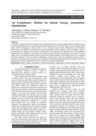
  • 4. Alexandre A. Motta Int. Journal of Engineering Research and Applications www.ijera.com ISSN: 2248-9622, Vol. 5, Issue 9, (Part - 1) September 2015, pp.07-19 www.ijera.com 10 | P a g e Table 1: Data and limits for the variables and constraints in the application Variable Bennett (1998) Minimum Maximum penetrator diameter 0.025 m 0.020 m 0.030 m penetrator length-diameter ratio 16.0 12.0 20.0 penetrator density 16,500 kg/m3 14,000 kg/m3 18,600 kg/m3 sabot-penetrator length ratio 0.760 0.500 0.850 sabot mean diam-bore diam ratio 0.500 0.500 0.850 sabot density 2,710 kg/m3 2,000 kg/m3 7,850 kg/m3 charge mass 6.700 kg 6.500 kg 7.200 kg charge force constant 951,000 J/kg 940,000 J/kg 1,050,000 J/kg charge α 1.680E-9 1.680E-9 1.680E-9 charge β 0.993 0.950 1.000 charge ballistic size 0.0015 m 0.0012 m 0.0018 m charge form function 0.190 -0.050 0.200 propellant shape stick Stick Constraint NSSS 63 MPa N/A 100 MPa Pb 462 MPa N/A 550 MPa AB 33% 27% 35% III. METHOD AND INITIAL RESULTS 3.1 The method The choice for GA as optimization method follows from the problem characteristics: it is a multi-variable problem with conflicting objectives and a variety of constraints. The implementation was validated using the examples provided in Bennett (1998). In GA, a random population is generated and a value of fitness is attributed to each individual. Individuals in a given population are ranked according to this value and elitism, cross-over and mutation operations can be applied producing a new generation. This generation will be ranked as the first and new operations may be applied (Goldberg, 1989 and Motta, 2004). This is repeated successively until a criterion is met  in the present work a previously selected number of generations. The strategy used by Motta & Ebecken (2006) was selected for the present work: each set of parameters (or variables) were arranged in an array, constituting an individual, a set of individuals constituting a generation. The main difference is that binary codification was only used to perform cross- over and mutation operations. All other operations were performed in decimal, double precision codification. Similarly to this work, random mono- point cross-over and mutation operations were implemented in non-elite members of the population. An initial population of individuals with random attributes (valid variable values) is generated and their fitness determined, after which they are ranked and the non-elite members submitted to cross-over and mutation operations (according to the respective probabilities of occurrence), resulting in a new generation. This process is repeated until a criterion is reached (in this work, a pre-selected number of generations). The process to determine the fitness of an individual  or a configuration, a set of variables, followed the ballistic model described in item 2: the muzzle velocity was calculated using the interior ballistics model, feeding the exterior ballistics model to determine the strike velocity which was used by the terminal ballistics model to determine the penetration achieved by that configuration. The constraints AB, NSSS and Pb calculated in the interior ballistics model and other characteristics such as penetrator length or charge mass can be used to penalize a configuration. Initially, individuals with values outside the limits shown in Table 1 were given nil fitness but this strategy proved to lead to results that although reasonably similar and improved when compared to state-of-art ammunition performance lacked convergence in a strict sense. Therefore, other penalisation methods are being tested as discussed in item 3.2. 3.2 Sensitivity A sensitivity analyses was conducted to provide insight with respect to the impact of small variations in the values of the variables on performance. Charge mass variation was selected to illustrate this in the present work. Simulations were run with fixed values for all variables but the charge mass (all in the valid range) as shown in Table 2. The results are presented in Table 3. The application returned zero fitness for some values but it was not continue. It can be observed that variations in the charge mass between 7.01043 kg and 7.01473 kg  only 430 g, produce and unexpected result. The non-zero values in Table 3 are plotted in Fig. 1. These results are reproducible. This model is highly sensitive to small variations in the parameters and this impacts convergence, as
  • 5. Alexandre A. Motta Int. Journal of Engineering Research and Applications www.ijera.com ISSN: 2248-9622, Vol. 5, Issue 9, (Part - 1) September 2015, pp.07-19 www.ijera.com 11 | P a g e shown in item 3.3. Table 2: Parameters for sensitiveness analysis Variable Value Minimum Maximum penetrator diameter 0.02870 m 0.020 m 0.030 m penetrator length-diameter ratio 19.75 12.0 20.0 penetrator density 18202 kg/m3 14000 kg/m3 18600 kg/m3 sabot-penetrator length ratio 0.600 0.500 0.850 sabot mean diam-bore diam ratio 0.540 0.500 0.850 sabot density 2137.64 kg/m3 2000 kg/m3 7850 kg/m3 charge mass variable 6.500 kg 7.200 kg charge force constant 1032460 J/kg 940000 J/kg 1050000 J/kg charge α 1.6760E-09 1.680E-9 1.680E-9 charge β 0.995 0.950 1.000 charge ballistic size 1.70 E-3 m 1.20E-3 m 1.8E-3 m charge form function 0.095 -0.050 0.200 propellant shape stick stick or grain gun chamber volume 0.0078 m 0.007 m3 0.009 m3 shot travel 6.611 m 4.50 m 7.20 m Table 3: Fitness according to the variation of the charge mass Charge Mass (kg) Penetration (m) 7.01043 0.66063 7.01065 0.66068 7.01086 0.66073 7.01108 0.00000 7.01129 0.00000 7.01151 0.00000 7.01172 0.00000 7.01194 0.00000 7.01215 0.00000 7.01237 0.00000 7.01258 0.66114 7.01280 0.66074 7.01301 0.66079 7.01323 0.66084 7.01344 0.66089 7.01366 0.66095 7.01387 0.66100 7.01409 0.66105 7.01430 0.66110 7.01452 0.00000 7.01473 0.66120
  • 6. Alexandre A. Motta Int. Journal of Engineering Research and Applications www.ijera.com ISSN: 2248-9622, Vol. 5, Issue 9, (Part - 1) September 2015, pp.07-19 www.ijera.com 12 | P a g e 0.6605 0.6610 0.6615 7.01043 7.01065 7.01086 7.01108 7.01129 7.01151 7.01172 7.01194 7.01215 7.01237 7.01258 7.01280 7.01301 7.01323 7.01344 7.01366 7.01387 7.01409 7.01430 7.01452 7.01473 Penetration(m) Charge Mass (kg) SensitivityAnalyses Fig. 1: Sensitivity analyses: fitness variation according to different charge masses 3.3 Convergence In this work, convergence refers to the generation in which the best fit individual (the set of parameters that resulted in the highest penetration) was found. After the implementation strategy was resolved, it was decided to use a population with 400 individuals – it was not observed a direct correlation between the size of the population and convergence although populations with less than 100 individuals were not tried. The rates of elitism, cross-over and mutation also seemed to have little impact in convergence. Table 4 shows five results obtained after 10,000 generations with 2% elitism, 70% cross-over rate and 90% mutation rate. One may argue that these rates are exaggerated, but virtually dozen executions with varied rates showed no direct correlation between them and convergence or the results obtained. Table 4: Results obtained after 10,000 generations Elitism 2% Cross-over rate 70% Mutation Rate 90% Generations 10000 Execution #: 1 2 3 4 5 Highest Fitness: 0.5177 0.5111 0.5076 0.5163 0.5205 Generation: 7268 5555 2053 6777 8384 Best fit indiv.: Penetrator Diam 0.0203 0.0223 0.0228 0.0218 0.0223 Pen L-D Ratio 18.9196 19.6382 19.0821 19.3108 19.3809 Penetrator Dens 17748.150 15705.612 15541.733 16458.950 17455.637 Sabot L-Ratio 0.6587 0.5909 0.5527 0.6233 0.6341 Sabot Diam-Ratio 0.5328 0.5615 0.5251 0.5357 0.5079 Sabot Density 2349.428 2048.758 2324.745 2039.092 2115.995 Charge Mass 7.1599 6.8416 7.0982 6.9152 7.1960 Charge Force Constant 1.050E+06 1.045E+06 1.040E+06 1.025E+06 1.026E+06 Charge α 0.9983 0.9965 0.9910 0.9977 0.9969 Charge β 1.718E-09 1.567E-09 1.786E-09 1.794E-09 1.541E-09 Charge Ball. Size 0.0016 0.0014 0.0014 0.0015 0.0014 Charge Form Func 0.1015 0.1241 -0.0451 0.0254 -0.0456 Constraints: AB 0.3214 0.3113 0.3045 0.2702 0.3165 NSSS 1.736E+07 1.693E+07 1.878E+07 1.666E+07 1.750E+07 Pb 1.158E+08 1.086E+08 1.142E+08 1.074E+08 1.142E+08 Convergence for the executions showed in Table 4 can be observed in Fig. 2. The results are very good and above what is expected in practical terms for this type of ammunition, but it is not considered that convergence was achieved. It should be noted that a logarithmic scale was used for the Generation axis
  • 7. Alexandre A. Motta Int. Journal of Engineering Research and Applications www.ijera.com ISSN: 2248-9622, Vol. 5, Issue 9, (Part - 1) September 2015, pp.07-19 www.ijera.com 13 | P a g e (horizontal). Table 5 and Fig. 3 show the same outputs for 30,000 generations without any improvement in the convergence. Table 6 and Fig. 4 present the results using different cross-over rates and Table 7 and Fig. 5 present the results using different mutation rates (10,000 generations). There are noticeable differences in the values of most variables and clearly the method, as is, did not achieve what is expected, a unique, reproducible solution. Increasing the number of generations did not produce any impact in the convergence. 0.350 0.450 0.550 1 10 100 1000 10000 Penetration(m) Generation Convergence Exec. #1 Exec. #2 Exec. #3 Exec. #4 Exec. #5 Fig. 2: Convergence (penetration achieved) after 10,000 generations Table 5: Results obtained after 30,000 generations Elitism 2% Cross-over rate 70% Mutation Rate 90% Generations 30000 Execution #: 1 2 3 4 5 Highest Fitness: 0.5187 0.5206 0.5117 0.5206 0.5180 Generation: 14959 7666 26695 28076 22069 Best fit indiv.: Penetrator Diam 0.0222 0.0212 0.0204 0.0225 0.0212 Pen L-D Ratio 19.9960 19.7749 19.8852 19.6862 19.3110 Penetrator Dens 14852.957 17817.392 16355.482 16325.378 17694.685 Sabot L-Ratio 0.5688 0.6081 0.6338 0.7042 0.6546 Sabot Diam-Ratio 0.5550 0.5020 0.5679 0.5173 0.5079 Sabot Density 2210.531 2361.125 2197.778 2017.631 2055.335 Charge Mass 7.0600 7.1561 7.1919 7.1252 6.6124 Charge Force Const 1.045E+06 1.007E+06 1.042E+06 1.048E+06 1.047E+06 Charge α 0.9989 0.9928 0.9956 0.9830 0.9924 Charge β 1.772E-09 1.548E-09 1.561E-09 1.698E-09 1.558E-09 Charge Ball. Size 0.0017 0.0013 0.0014 0.0013 0.0012 Charge Form Funct 0.0567 0.0845 -0.0038 0.1582 0.1427 Constraints: AB 0.3041 0.3401 0.3452 0.3473 0.2946 NSSS 1.713E+07 1.799E+07 1.698E+07 1.460E+07 1.676E+07 Pb 1.130E+08 1.110E+08 1.182E+08 1.135E+08 1.050E+08
  • 8. Alexandre A. Motta Int. Journal of Engineering Research and Applications www.ijera.com ISSN: 2248-9622, Vol. 5, Issue 9, (Part - 1) September 2015, pp.07-19 www.ijera.com 14 | P a g e 0.350 0.450 0.550 1 10 100 1000 10000 Penetration(m) Generation Convergence Exec. #1 Exec. #2 Exec. #3 Exec. #4 Exec. #5 Fig. 3: Convergence (penetration achieved) after 30,000 generations Table 6: Results obtained after 10,000 generations using different cross-over rates Execution #: 1 2 3 4 5 Elitism 2% Cross-over rate 40% 50% 60% 70% 80% Mutation Rate 90% Generations 10000 Highest Fitness: 0.5211 0.5209 0.5195 0.5060 0.5116 Generation: 1774 7195 6288 7707 3770 Best fit indiv.: Penetrator Diam 0.0205 0.0229 0.0224 0.0202 0.0212 Pen L-D Ratio 19.3443 19.9995 19.9028 19.9048 19.1149 Penetrator Dens 17858.288 14360.685 15729.378 17897.276 17923.025 Sabot L-Ratio 0.6459 0.5269 0.5638 0.7234 0.6661 Sabot Diam-Ratio 0.5309 0.5370 0.6065 0.5759 0.5218 Sabot Density 2212.802 2232.409 2068.758 2158.166 2117.647 Charge Mass 7.1469 7.0328 7.1450 6.9197 7.0469 Charge Force Const 1.014E+06 1.044E+06 1.043E+06 1.047E+06 1.037E+06 Charge α 0.9923 0.9853 0.9849 0.9851 0.9940 Charge β 1.686E-09 1.724E-09 1.720E-09 1.781E-09 1.629E-09 Charge Ball. Size 0.0014 0.0012 0.0013 0.0013 0.0014 Charge Form Funct 0.1509 0.0520 0.0174 0.1493 0.0258 Constraints: AB 0.3441 0.3179 0.3096 0.3161 0.3441 NSSS 17241404 18332357 17828085 14438789 17242462 Pb 111372340 112782270 113922250 109518160 113924370
  • 9. Alexandre A. Motta Int. Journal of Engineering Research and Applications www.ijera.com ISSN: 2248-9622, Vol. 5, Issue 9, (Part - 1) September 2015, pp.07-19 www.ijera.com 15 | P a g e 0.350 0.450 0.550 1 10 100 1000 10000 Penetration(m) Generation Convergence TXC = 40% TXC = 50% TXC = 60% TXC = 70% TXC = 80% Fig. 4: Convergence after 10,000 generations using different cross-over rates Table 7: Results obtained after 10,000 generations using different mutation rates Execution #: 1 2 3 4 5 Elitism 2% Cross-over rate 50% Mutation Rate 40% 50% 60% 70% 80% Generations 10000 Highest Fitness: 0.5276 0.5151 0.5193 0.5277 0.5252 Generation: 3392 5747 8601 9743 7733 Best fit indiv.: Penetrator Diam 0.0215 0.0208 0.0204 0.0206 0.0214 Pen L-D Ratio 19.8844 19.0818 19.0538 19.5370 19.9750 Penetrator Dens 16431.377 17454.163 18282.739 17792.577 17078.896 Sabot L-Ratio 0.6682 0.6437 0.6325 0.6188 0.5974 Sabot Diam-Ratio 0.5378 0.5110 0.5115 0.5309 0.5317 Sabot Density 2009.819 2267.297 2405.675 2271.450 2166.429 Charge Mass 7.0769 6.8986 7.0421 7.1705 7.0330 Charge Force Const 1.040E+06 1.022E+06 1.034E+06 1.025E+06 1.020E+06 Charge α 0.9954 0.9896 0.9993 0.9951 0.9863 Charge β 1.748E-09 1.677E-09 1.610E-09 1.550E-09 1.695E-09 Charge Ball. Size 0.0016 0.0012 0.0014 0.0013 0.0013 Charge Form Funct 0.1812 0.1128 0.0062 0.0401 0.1252 Constraints: AB 0.3466 0.2813 0.2945 0.3211 0.3424 NSSS 15651065 16730535 18227144 18199768 17863689 Pb 112576340 106645640 112342570 113637770 110342740
  • 10. Alexandre A. Motta Int. Journal of Engineering Research and Applications www.ijera.com ISSN: 2248-9622, Vol. 5, Issue 9, (Part - 1) September 2015, pp.07-19 www.ijera.com 16 | P a g e 0.350 0.450 0.550 1 10 100 1000 10000 Penetration(m) Generation Convergence TXM = 40% TXM = 50% TXM = 60% TXM = 70% TXM = 80% Fig. 5: Convergence after 10,000 generations using different mutation rates 3.4 Other strategies to improve convergence In order to improve convergence, different penalisation strategies promoting smoother, gradual reduction on fitness as the variables approach the limits of the allowed intervals are implemented. Such strategies were used by Motta & Ebecken (2006) and account for less tangible aspects like loss of accuracy as AB moves away from the centre of the allowed interval, increased stowage space required for longer rounds, cost etc. Figure 6 shows multipliers that can be used to penalise the individuals according to the constraints. The curve for AB is parametric of fourth order and was designed to not heavily penalise central values (with respect to the allowed range). The other curves represent linear progressive penalisation after a threshold is reached. These implemented penalisations are for demonstration purposes and specific rules must be developed for individual cases. 0.00 0.20 0.40 0.60 0.80 1.00 1.20 -1.50 -1.00 -0.50 0.00 0.50 1.00 1.50 Multiplier Value with respect to the mean value Penalisationaccording to AB 0.00 0.20 0.40 0.60 0.80 1.00 1.20 0.0E+00 5.0E+07 1.0E+08 Multiplier NSSS Penalisationaccording to NSSS 0.0 0.2 0.4 0.6 0.8 1.0 1.2 0.E+00 1.E+08 2.E+08 3.E+08 4.E+08 5.E+08 6.E+08 Multiplier Pb Penalisationaccording to Pb (a) (b) (c) Fig. 6: Penalisations for AB (a), NSSS (b) and Pb (c) Table 8 and Fig. 7 show the results and convergence evolution applying such constraint-related penalties. It can be observed that this conservative approach leads to lower penetration values and that the most fit individual may not be the one with highest penetration.
  • 11. Alexandre A. Motta Int. Journal of Engineering Research and Applications www.ijera.com ISSN: 2248-9622, Vol. 5, Issue 9, (Part - 1) September 2015, pp.07-19 www.ijera.com 17 | P a g e Table 8: Results obtained using constraint-related penalisation Execution #: 1 2 3 4 5 Elitism 2% Cross-over rate 70% Mutation Rate 90% Generations 10000 Highest Fitness: 0.3665 0.3696 0.3788 0.3729 0.3757 Highest Penetration: 0.3920 0.3829 0.3868 0.3797 0.3873 Generation: 7687 3392 6174 391 4712 Best fit indiv.: Penetrator Diam 0.0201 0.0208 0.0202 0.0201 0.0204 Pen L-D Ratio 19.9345 19.0921 19.8904 18.6665 19.9337 Penetrator Dens 17698.183 18069.224 18251.671 15333.106 17402.227 Sabot L-Ratio 0.8213 0.7625 0.7575 0.7652 0.7173 Sabot Diam-Ratio 0.5101 0.5049 0.5016 0.5051 0.5103 Sabot Density 2146.130 2089.920 2286.510 2091.233 2198.692 Charge Mass 7.1219 7.1595 7.1907 7.1768 7.1778 Charge Force Const 9.923E+05 1.007E+06 1.033E+06 1.032E+06 1.038E+06 Charge α 0.9733 0.9819 0.9888 0.9903 0.9887 Charge β 1.783E-09 1.693E-09 1.525E-09 1.732E-09 1.737E-09 Charge Ball. Size 0.0013 0.0014 0.0015 0.0016 0.0017 Charge Form Funct 0.1221 0.0153 -0.0158 -0.0359 0.0116 0.200 0.300 0.400 0.500 1 10 100 1000 10000 Penetration(m) Generation Convergence Exec. #1 Exec. #2 Exec. #3 Exec. #4 Exec. #5 Fig. 7: Convergence applying constraint-related penalties Analysts should pay attention to the fact that the individual with higher penetration (performance) may not be the best fit in the population and thoughtful considerations might be necessary to assess whether adequate penalisation criteria are in place. IV. CONCLUSION The problem of finding an optimal kinetic ammunition (long rod only) using evolutionary methods is a challenging task due to the high sensitivity of the problem to small variations in the variables involved. The present work is based on the model proposed by Bennett (1998). As the author cites in his work, „the results show clearly the interdependence between the various gun and ammunition parameters, and the penetration that can be achieved‟. The method herein proposed allowed to identify physically meaningful sets of parameters that result in very high penetrations, of the order of 50% above
  • 12. Alexandre A. Motta Int. Journal of Engineering Research and Applications www.ijera.com ISSN: 2248-9622, Vol. 5, Issue 9, (Part - 1) September 2015, pp.07-19 www.ijera.com 18 | P a g e the highest value presented in Bennett (1998). Despite of the lack of convergence to a single value – meaning that improvements are still required to find „the optimal‟ set of parameters, the method provides means to investigate the interdependence between the variables. The resulting differences do not disqualify the method but reinforce the need for keeping a critical thinking. Traditionally, ammunition designers rely on empirical data and experience to conceive new munitions. The present method provides a novel, innovative approach to improve performance, intending to determine the optimal parameters in the configuration of kinetic ammunition (long rod only). The method can also be easily modified to adopt other models or to take into consideration other set of variables. V. SUMMARY The present work introduces a method for the optimization of kinetic energy (long rod only) ammunition with respect to its terminal effects on steel homogeneous targets using an evolutionary method, i.e. Genetic Algorithms. The terminal effect, its performance, is measured by the penetration achieved against rolled homogenous armour (steel) at a fixed distance. The model adopted in the present work is simple, yet accurate enough to produce acceptable results, including all relevant aspects of the physical problem. It can be altered and improved, but increasing the complexity of the calculations does not alter the purpose of the method presented. Therefore, a simpler model is preferable for demonstration purposes. Although convergence of the method is yet to be understood and modifications must be implemented to allow the identification of the optimal configuration, results already provide valuable insights on the study of this class of problems and can be used to suggest design modifications to improve performance. Finally, the authors suggest that artificial intelligence / machine learning can also be incorporated with potential improved results, as well as more sophisticated models. REFERENCES [1.] Alekseevskii, V. P., 1966. Penetration of a Rod into a Target at High Velocity, Combustion, Explosion and Shock Waves; 2: 63-66. [2.] Anderson Jr, C. E., Morris, B. L. & Littlefield, D. L., 1992. A Penetration Mechanics Database. SwRI Report 3593/001, Southwest Research Institute, San Antonio, TX. [3.] Bennett, M. D., 1998. Long Rod Penetration Perfomance, Journal of Battlefield Technology, Vol. 1, No. 3, pp. 1-6. [4.] Doig, A., 1998. Some Metallurgical Aspects of Shaped Charge Liners, Journal of Battlefield Technology, Vol. 1, No. 1, pp. 1- 3. [5.] Goldberg, D. E., 1989. Genetic Algorithms in Search, Optimization, and Machine Learning. Addison-Wesley: Boston., MA, USA. [6.] Goldsmith, W., 1999. Non-Ideal Projectile Impact on Targets, International Journal of Impact Engineering; 22: 95-395. [7.] Grace, F. I., 1993. Nonsteady Penetration of Long Rods into Semi-Infinite Targets, International Journal of Impact Engineering; 14: 303-314. [8.] Held, M., 1991. Hydrodynamic Theory of Shaped Charge Jet Penetration, Journal of Explosives and Propellants, Vol. 9, pp. 9- 24. [9.] Hohler, V. & Stilp, A., 1977. Penetration of Steel and High Density Rods in Semi-Infinte Steel Targets, Proceedings Third International Symposium on Ballistics, Karlsruhe, Germany. [10.] Hohler, V. & Stilp, A., 1978. Study of the Penetration Behaviour of Rods for a Wide Range of Target Densities", Proceedings Fourth International Symposium on Ballistics, Monterey, California. [11.] Lan, B., & Wen, H. M., 2010. Alekseevskii- Tate Revisited: an Extension to the Modified Hydynamic Theory of Long-Rod Penetration, Sci. China, Ser, E. 53(5): 1364- 1373. [12.] Longdon, L.W., 1987. Textbook of Gunnery and Ballistics, Vol. 1, HMSO, London. [13.] McCoy, R. L., 1999. Modern Exterior Ballistics, Schiffer Publishing Ltd, Atglen, PA. [14.] Motta, A. A., 2004. Underwater Explosive Charges Optimization with Respect to Their Terminal Effects on Submerged Steel Structures. DSc Dissertation, Federal University of Rio de Janeiro/Rio de Janeiro. [15.] Motta, A.A., & Ebecken, N.F.F, 2006. On the Application of Genetic Algorithms in Underwater Explosive Charges Optimization, International Journal for Computational Methods in Engineering Science and Mechanics, Vol. 8, Iss. 1. DOI: 10.1080/15502280601006140. [16.] Jones, S. E., Gillis, P. P. & Foster, J. C., 1987. On the penetration of semi-infinite targets by long Rods. Journal of the Mechanics and Physics of Solids; 35(1): 121-131.
  • 13. Alexandre A. Motta Int. Journal of Engineering Research and Applications www.ijera.com ISSN: 2248-9622, Vol. 5, Issue 9, (Part - 1) September 2015, pp.07-19 www.ijera.com 19 | P a g e [17.] Orphal, D. L., 2006. Explosions and Impacts, International Journal of Impact Engineering; 33: 496-545. [18.] Rosenberg, Z., 1990. On the Hydrodynamic Theory of Long-Rod Penetration, International Journal of Impact Engineering; 10: 483-486. [19.] Rubin, M. B. & Yarin, A. L., 2002. A Generalized Formula for the Penetration Depth of a Deformable Projectile, International Journal of Impact Engineering; 27: 387-398. [20.] Segletes, S. B. & Walters, W. P., 2003. Extensions to the Exact Solution of the Long Rod Penetration/Erosion Equations, International Journal of Impact Engineering; 28: 363-376. [21.] Tate, A., 1967. A Theory for the Deceleration of Long Rods after Impact, Journal of the Mechanics and Physics of Solids; 15: 387-399. [22.] Tate, A., 1969. Further Results in the Theory of Long Rod Penetration, Journal of the Mechanics and Physics of Solids.,17, 141-15C. [23.] Walker, J. D. & Anderson Jr, C. E., 1995. A Time-Dependent Model for Long-Rod Penetration, International Journal of Impact Engineering; 16(1): 19-48. [24.] Walker, J. D., 2001. Hypervelocity Penetration Modeling: Momentum VS. Energy and Energy Transfer Mechanisms, International Journal of Impact Engineering; 26: 809-822. [25.] Walters, W. P. & Segletes, S. B., 1991. An Exact Solution of the Long Rod Penetration Equations, International Journal of Impact Engineering; 11(2): 225-231. [26.] Wang, P. & Jones, S. E., 1996. An Elementary Theory of One-Dimensional Rod Penetration Using a New Estimate for Pressure, International Journal of Impact Engineering; 18(3): 265-279. [27.] Wen, H.M., He, Y. & Lan, B., 2011. A combined numerical and theoretical study on the penetration of a jacketed Rod into semi-infinite target. International Journal of Impact Engineering; 38:1001-1010. [28.] Wen, H.M., He, Y. & Lan, B., 2010. Analytical Model for Cratering of Semi- Infinite Metal Targets by Long Rod Penetration, Sci. China, Tech. Sci.; 53: 3189-3196. [29.] Wright, T. W., 1983. A Survey of Penetration Mechanics for Long Rods, In J. Chandra and J. E. Flaherty (eds.), Computational Aspects of Penetration Mechanics, Springer, New York, pp. 85- 106. [30.] Zook, J. A., Frank, K. & Silsby, G. F., 1992. Terminal Ballistics Test and Analysis Guidelines for the Penetration Branch, BRL- MR-3960, U.S. Army Ballistic Research Laboratory, Aberdeen Proving Ground, MD.