Download to read offline
![Sachin M. Shinde et al. Int. Journal of Engineering Research and Application ww.ijera.com
Vol. 3, Issue 5, Sep-Oct 2013, pp.13-18
www.ijera.com 13 | P a g e
Probabilistic Design and Random Optimization of Aerofoil Wing
by Using Finite Element Method
Mr.Sachin M. Shinde*,Prof.Dr.B.P. Ronge**, Prof.Dr.P.M.Pawar**
*(Student, Department of Mechanical Engineering, SVERI’s College of Engineering,Pandhapur)
** (Professor, Department of Mechanical Engineering, SVERI’s College of Engineering, Pandhapur)
ABSTRACT: This study represents simulation of aerofoil composite beam by using Monte Carlo method
i.e.direct sampling. A three dimensional transient analysis of large displacement type has been carried out.Finite
element analysis of NACA0012 aerofoil composite structure has been carried out and uncertainty in bending
stress is analyzed. More over optimization of selected design variables has been carried out by using random
optimization method. Bending stress was objective function.Chord length , elastic modulus of epoxy graphite,
ply angle of aerofoil section, Beam length , moment of inertia and force are randomly varied within effective
range and their effect on bending stress has been analyzed.In order to validate the results, one loop of simulation
is benchmarked from results in literature. Ultimately, best set of optimized design variable is proposed to reduce
bending stress under different loading condition.
Key words: -Aerofoil wing, Monte Carlo Simulation, Random Optimization.
I. INTRODUCTION
Composite materials have found increasing
use in aerospace and civil engineering construction.
One of the common areas of application is panels and
aerofoils construction where composite materials
with complex lay-ups are used. The following
properties can be improved when composite materials
are used: specific strength, specific stiffness, weight,
and fatigue life. The thin-walled beams of open cross-
sections are used extensively in space systems as
space erectable booms installed on space craft; in
aeronautical industry both as direct load-carrying
members and as stiffener members. In addition, they
are used as well in marine and civil engineering,
whereas the I-beams, in the fabrication of flex beams
of bearing less helicopter rotor [1].Thin- walled
structures are integral part of an aircraft [2]. That is
the reason why many researchers consider it in their
studies and published it in scholarly articles. Chan
and his students focused on thin-walled beams with
different cross-sections.Among their studies, Chan
and Dermirhan [3] considered first a circular cross
section thin-walled composite beam. They developed
a new and simple closed-form method to calculate its
bending stiffness. Then, Lin and Chan [4] continued
the work with an elliptical cross section thin-walled
composite beam. Later, Syed and Chan [5] included
hat-sectioned composite beams. And most recently,
Rao and Chan [6] expanded the work to consider
laminated tapered tubes. Ascione et al. [7] presented a
method that formulates one-dimensional kinematical
model that is able to study the static behavior of fiber-
reinforced polymer thin-walled beams. It’s well
known that the statics of composite beam is strongly
influenced by shear deformability because of the low
values of the elastic shear module. Such a feature
cannot be analyzed by Vlasov’s theory, which assume
that the shear strains are negligible along the middle
line of the cross-section. Ferrero et al. [8] proposed
that the stress field in thin-walled composite beams
due to attwisting moment is not correctly modeled by
classical analytical theories, so numerical modelingis
essential. Therefore, they developed method with a
simple way of determining stress and stiffness in this
type of structures where the constrained warping
effect can be taken into account. They worked with
both open and closed cross sections. Also, to check
the validity of the method for structures made of
composite materials, a beam with thin, composite
walls were studied. Wu et al. [9] presented a
procedure for analyzing the mechanical behavior of
laminated thin-walled composite box beam under
torsional load without external restraint. Some
analyses have been formulated to analyzed composite
box beam with varying levels of assumptions [10-
13].Therefore, analysis of aerofoil wing under
varying loading condition is key to improve the
design and provide good agreement in results.
II .SIMULATION
The Monte Carlo Simulation method is the most
common and traditional method for a probabilistic
analysis. This method simulates how virtual
components behave the way they are built. Present
work uses FEM package ANSYS for analysis of
composite beam of hollow NACA0012 aerofoil
shape.FEM package of ANSYS is used. Element
selected for meshing the geometry of the specimen is
shell 181.Material properties of epoxy graphite are
entered. Geometry of model is drawn in ANSYS
software. Geometry is meshed by giving element size
5mm. Mapped type of meshing is used. Meshed
model of specimen is shown below in figure in 1.
RESEARCH ARTICLE OPEN ACCESS](https://image.slidesharecdn.com/d351318-130911055639-phpapp01/85/D351318-1-320.jpg)
![Sachin M. Shinde et al. Int. Journal of Engineering Research and Application ww.ijera.com
Vol. 3, Issue 5, Sep-Oct 2013, pp.13-18
www.ijera.com 13 | P a g e
Probabilistic Design and Random Optimization of Aerofoil Wing
by Using Finite Element Method
Mr.Sachin M. Shinde*,Prof.Dr.B.P. Ronge**, Prof.Dr.P.M.Pawar**
*(Student, Department of Mechanical Engineering, SVERI’s College of Engineering,Pandhapur)
** (Professor, Department of Mechanical Engineering, SVERI’s College of Engineering, Pandhapur)
ABSTRACT: This study represents simulation of aerofoil composite beam by using Monte Carlo method
i.e.direct sampling. A three dimensional transient analysis of large displacement type has been carried out.Finite
element analysis of NACA0012 aerofoil composite structure has been carried out and uncertainty in bending
stress is analyzed. More over optimization of selected design variables has been carried out by using random
optimization method. Bending stress was objective function.Chord length , elastic modulus of epoxy graphite,
ply angle of aerofoil section, Beam length , moment of inertia and force are randomly varied within effective
range and their effect on bending stress has been analyzed.In order to validate the results, one loop of simulation
is benchmarked from results in literature. Ultimately, best set of optimized design variable is proposed to reduce
bending stress under different loading condition.
Key words: -Aerofoil wing, Monte Carlo Simulation, Random Optimization.
I. INTRODUCTION
Composite materials have found increasing
use in aerospace and civil engineering construction.
One of the common areas of application is panels and
aerofoils construction where composite materials
with complex lay-ups are used. The following
properties can be improved when composite materials
are used: specific strength, specific stiffness, weight,
and fatigue life. The thin-walled beams of open cross-
sections are used extensively in space systems as
space erectable booms installed on space craft; in
aeronautical industry both as direct load-carrying
members and as stiffener members. In addition, they
are used as well in marine and civil engineering,
whereas the I-beams, in the fabrication of flex beams
of bearing less helicopter rotor [1].Thin- walled
structures are integral part of an aircraft [2]. That is
the reason why many researchers consider it in their
studies and published it in scholarly articles. Chan
and his students focused on thin-walled beams with
different cross-sections.Among their studies, Chan
and Dermirhan [3] considered first a circular cross
section thin-walled composite beam. They developed
a new and simple closed-form method to calculate its
bending stiffness. Then, Lin and Chan [4] continued
the work with an elliptical cross section thin-walled
composite beam. Later, Syed and Chan [5] included
hat-sectioned composite beams. And most recently,
Rao and Chan [6] expanded the work to consider
laminated tapered tubes. Ascione et al. [7] presented a
method that formulates one-dimensional kinematical
model that is able to study the static behavior of fiber-
reinforced polymer thin-walled beams. It’s well
known that the statics of composite beam is strongly
influenced by shear deformability because of the low
values of the elastic shear module. Such a feature
cannot be analyzed by Vlasov’s theory, which assume
that the shear strains are negligible along the middle
line of the cross-section. Ferrero et al. [8] proposed
that the stress field in thin-walled composite beams
due to attwisting moment is not correctly modeled by
classical analytical theories, so numerical modelingis
essential. Therefore, they developed method with a
simple way of determining stress and stiffness in this
type of structures where the constrained warping
effect can be taken into account. They worked with
both open and closed cross sections. Also, to check
the validity of the method for structures made of
composite materials, a beam with thin, composite
walls were studied. Wu et al. [9] presented a
procedure for analyzing the mechanical behavior of
laminated thin-walled composite box beam under
torsional load without external restraint. Some
analyses have been formulated to analyzed composite
box beam with varying levels of assumptions [10-
13].Therefore, analysis of aerofoil wing under
varying loading condition is key to improve the
design and provide good agreement in results.
II .SIMULATION
The Monte Carlo Simulation method is the most
common and traditional method for a probabilistic
analysis. This method simulates how virtual
components behave the way they are built. Present
work uses FEM package ANSYS for analysis of
composite beam of hollow NACA0012 aerofoil
shape.FEM package of ANSYS is used. Element
selected for meshing the geometry of the specimen is
shell 181.Material properties of epoxy graphite are
entered. Geometry of model is drawn in ANSYS
software. Geometry is meshed by giving element size
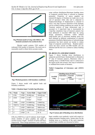
5mm. Mapped type of meshing is used. Meshed
model of specimen is shown below in figure in 1.
RESEARCH ARTICLE OPEN ACCESS](https://image.slidesharecdn.com/d351318-130911055639-phpapp01/75/D351318-1-2048.jpg)
![Sachin M. Shinde et al. Int. Journal of Engineering Research and Application ww.ijera.com
Vol. 3, Issue 5, Sep-Oct 2013, pp.13-18
www.ijera.com 18 | P a g e
REFERENCES
[1]. Lee, J., and Lee, S., “Flexural-torsional
behavior of thin-walled composite beams”,
ELSEVIER, Thin-walled Structures, vol. 42,
2004, pp. 1293-1305.
[2]. Mitra, M., Gopalakrishnan, S., and
Seetharama, M., “A new super convergent
thin walled composite beam element for
analysis of box beam structures”,
ELSEVIER, International Journal of Solids
and Structures, vol. 41, 2004, pp. 1491-1518.
[3]. Chan, W. S., and Demirhan K. C., “A Simple
Closed-Form Solution of Bending Stiffness
for Laminated Composite Tubes”, Journal of
Reinforced Plastic & Composites, vol. 19,
2000, pp. 278-291.
[4]. Lin, C. Y., and Chan, W. S., “A Simple
Analytical Method for Analyzing Laminated
Composites Elliptical Tubes”, Proceedings of
the 17th Technical Conference of American
Society of Composites, Dearborn, Michigan
,2002.
[5]. Syed, K., and Chan, W., “Analysis of Hat-
Sectioned Reinforced Composite Beams”,
Proceedings of American Society for
Composites Conference, Dearborn, Michigan,
2006.
[6]. Rao, C., and Chan, W. S., “Analysis of
Laminated Composites Tapered Tubes”,
Department of Mechanical and Aerospace
Engineering, University of Texas at
Arlington.
[7]. Ascione, L., Feo, L., and Mancusi, G., “On
the statical behavior of fiber reinforced
polymer thin-walled beams”, ELSEVIER,
Composites, Part B, vol. 31, 2000, pp. 643-
654.
[8]. Ferrero, J. F., Barrau, J. J., Segura, J. M. ,
Castanie, B. , and Sudre, M., “Torsion ofthin-
walled composite beams with mid plane
symmetry”,ELSEVIER,Composite structures,
vol. 54, 2001, pp. 111-120.
[9]. Wu, Y., Zhu, Y., Lai, Y., Zhang, X., and Liu,
S., “Analysis of thin-walled composite
boxbeam under Torsional load without
external restraint”, ELSEVIER, Thin-
walledStructures, vol. 40, 2002, pp. 385-397.
[10]. Chuanxian, C., “Researches on bending and
torsional stiffness of thin-walled carbon
epoxy box beam”, Mechanics and Practice,
Beijing University Press, 1985.
[11]. Chandra, R., Stemple, A. D., and Chopra I.,
“Thin-walled composite beams underbending,
torsional and extensional loads”, Journal
Aircraft, 1990, vol. 27, 619-626.
[12]. Fei, Y., “A theory for bending and torsion of
the composite single cell thin-walled beam”,
Mechanics and Practice, 1994, vol. 16, pp.
37-40.
[13]. Min, J. S., Hyo, C. M., and In, L., “Static and
dynamic analysis of composite box beams
using large deflection theory”. Computer &
Structures, 1995, vol. 57, pp. 635-642.](https://image.slidesharecdn.com/d351318-130911055639-phpapp01/85/D351318-6-320.jpg)

This document summarizes a study that used finite element analysis and Monte Carlo simulation to analyze the probabilistic design and random optimization of an aerofoil wing made of composite materials. The study modeled an NACA0012 aerofoil composite structure in ANSYS and varied design parameters like chord length, ply angle, elastic modulus, and loading conditions randomly to analyze uncertainty in bending stress. Over 1000 simulations were run. Optimization was also performed to find a set of design variables that reduced the bending stress objective function. The best set reduced bending stress from 1131.79 N/mm2 to 180.58 N/mm2. The study concluded there was significant uncertainty when chord length and ply angle varied and provided correlations between design variables and bending