MIMO-OFDM SYSTEM IN RAYLEIGH FADDING CHANNEL
•
1 like•793 views

MIMO-OFDM (Multi Input Multi Output- Orthogonal Frequency Division Multiplexing) system is very popular technique for mobile communication. We found that Ergodic channel capacity has some limitation in MIMO-OFDM system. So Ergodic channel capacity optimization is necessary to improve the performance of MIMO-OFDM System.
![www.ijeee-apm.com International Journal of Electrical & Electronics Engineering 5
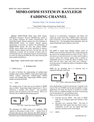
MISO is also termed transmit diversity. In this case, the
same data is transmitted redundantly from the two
transmitter antennas. The receiver is then able to receive the
optimum signal which it can then use to receive extract the
required data (Fig.3).
Fig. 3 MISO - Multiple Input Single Output
The advantage of using MISO is that the multiple antennas
and the redundancy coding processing is moved from the
receiver to the transmitter. In instances such as cellphone
UEs, this can be a significant advantage in terms of space for
the antennas and reducing the level of processing required in
the receiver for the redundancy coding. This has a positive
impact on size, cost and battery life as the lower level of
processing requires less battery consumption.
1.1.3 MIMO
There are more than one antenna at either end of the radio
link, this is termed MIMO - Multiple Input Multiple Output
(Fig.4). MIMO can be used to provide improvements in both
channel robustness as well as channel throughput.
Fig.4 MIMO - Multiple Input Multiple Output
In order to be able to benefit from MIMO fully it is
necessary to be able to utilise coding on the channels to
separate the data from the different paths. This requires
processing, but provides additional channel robustness / data
throughput capacity.There are many formats of MIMO that
can be used from SISO, through SIMO and MISO to the full
MIMO systems. These are all able to provide significant
improvements of performance, but generally at the cost of
additional processing and the number of antennas used.
Balances of performance against costs, size, processing
available and the resulting battery life need to be made when
choosing he correct option [1].
II OVERVIEW OF OFDM
OFDM is becoming a very popular multi-carrier modulation
technique for transmission of signals over wireless channels.
It converts a frequency-selective fading channel into a
collection of parallel at fading sub channels, which greatly
simplifies the structure of the receiver. The time domain
waveform of the subcarriers are orthogonal (sub channel and
subcarrier will be used interchangeably hereinafter), yet the
signal spectral corresponding to different subcarriers overlap
in frequency domain as shown in the fig.5. Hence, the
available bandwidth is utilized very efficiently in OFDM
systems without causing the ICI (inter-carrier interference).
By combining multiple low-data-rate subcarriers, OFDM
systems can provide a composite high-data-rate with a long
symbol duration. That helps to eliminate the ISI (inter-
symbol interference), which often occurs along with signals
of a short symbol duration in a multipath channel.
Fig. 5. OFDM Carrier
Advantage of OFDM systems are:-
High spectral efficiency;
Simple implementation by FFT (fast Fourier
transform);
Low receiver complexity;
Robustability for high-data-rate transmission
over multipath fading channel
Highflexibility in terms of link adaptation;
Disadvantages of OFDM systems are:-
Sensitive to frequency offsets, timing errors
and phase noise
Relatively higher peak-to-average power ratio
compared to single carrier system[2]
III OVERVIEW OF MIMO-OFDM SYSTEM
MIMO uses multiple antenna to transmit and receive
multiple wireless signal at a time causing better wireless
system performance to improve all the three parameter i.e.
speed, range and reliability compare to other conventional
system domain as shown in the fig.6. It well known that the
performance degradation takes place due to multipath fading
channel. Different equalization techniques are used to
combat effect of Inter Symbol Interference (ISI), but this can
be done at the cost of complexity. An alternative to these
equalizers is OFDM. Orthogonal frequency division
multiplexing is a modulation technique to carry a data on
different frequency channels. OFDM can provide simplicity
on both side i.e. transmitter and receiver, and also improve
the spectral efficiency of wireless system. Existing research
is mainly focused on obtaining the capacity and performance
analysis curves for various MIMO configurations, assuming
Rayleigh fading and independent and identically distributed
MIMO-OFDM sub-channel. So far, the capacity of MIMO-](data:image/gif;base64,R0lGODlhAQABAIAAAAAAAP///yH5BAEAAAAALAAAAAABAAEAAAIBRAA7)
Recommended
More Related Content
What's hot
What's hot (20)
Viewers also liked
Similar to MIMO-OFDM SYSTEM IN RAYLEIGH FADDING CHANNEL
Similar to MIMO-OFDM SYSTEM IN RAYLEIGH FADDING CHANNEL (20)
More from IJEEE
More from IJEEE (20)
Recently uploaded
Recently uploaded (20)
MIMO-OFDM SYSTEM IN RAYLEIGH FADDING CHANNEL
- 1. International Journal of Electrical & Electronics Engineering 4 www.ijeee-apm.com IJEEE, Vol. 1, Issue 2 (April 2014) e-ISSN: 1694-2310 | p-ISSN: 1694-2426 MIMO-OFDM SYSTEM IN RAYLEIGH FADDING CHANNEL Maninder Singh 1 , Dr. Hardeep Singh Saini2 1,2 Indo Global College of Engineering, Punjab, India 1 md_singh1989@yahoo.com, 2 hardeep_saini17@yahoo.co.in Abstract- MIMO-OFDM (Multi Input Multi Output- Orthogonal Frequency Division Multiplexing) system is very popular technique for mobile communication. We found that Ergodic channel capacity has some limitation in MIMO-OFDM system. So Ergodic channel capacity optimization is necessary to improve the performance of MIMO-OFDM System. We have that analyze MIMO- OFDM system deeply and various algorithms to improve Ergodic channel capacity and more over that the cost and complexity of system will not increase. In future work we will describes the new method that improve the performance of system by reducing the BER (bit error rate) removing ISI (Inter symbol interference). Index Terms- MIMO-OFDM, SISO, SIMO, MISO I INTRODUCTION 1.1 MIMO System:- In order to facilitate the understanding of multiple-input multiple-output systems (MIMO), single-input single-output (SISO) systems, single-input multiple-output (SIMO) systems and multiple-input single-output (MISO) systems models are discussed briefly: 1.1.1 SISO The simplest form of radio link can be defined in MIMO terms as SISO - Single Input Single Output (Fig.1). This is effectively a standard radio channel - this transmitter operates with one antenna as does the receiver. There is no diversity and no additional processing required. Fig.1 SISO - Single Input Single Output The advantage of a SISO system is its simplicity. SISO requires no processing in terms of the various forms of diversity that may be used. However the SISO channel is limited in its performance. Interference and fading will impact the system more than a MIMO system using some form of diversity, and the channel bandwidth is limited by Shannon's law - the throughput being dependent upon the channel bandwidth and the signal to noise ratio. 1.1.2 SIMO The SIMO or Single Input Multiple Output version of MIMO occurs where the transmitter has a single antenna and the receiver has multiple antennas as shown in Fig.2. This is also known as received diversity. It is often used to enable a receiver system that receives signals from a number of independent sources to combat the effects of fading. It has been used for many years with short wave listening / receiving stations to combat the effects of ionospheric fading and interference. SIMO has the advantage that it is relatively easy to implement although it does have Fig. 2 SIMO– Single Input Multiple Output some disadvantages in that the processing is required in the receiver.The use of SIMO may be quite acceptable in many applications, but where the receiver is located in a mobile device such as a cellphone handset, the levels of processing may be limited by size, cost and battery drain. There are two forms of SIMO that can be used: Switched diversity SIMO: This form of SIMO looks for the strongest signal and switches to that antenna. Maximum ratio combining SIMO: This form of SIMO takes both signals and sums them to give a combination. In this way, the signals from both antennas contribute to the overall signal. 1.1.2 MISO:-
- 2. www.ijeee-apm.com International Journal of Electrical & Electronics Engineering 5 MISO is also termed transmit diversity. In this case, the same data is transmitted redundantly from the two transmitter antennas. The receiver is then able to receive the optimum signal which it can then use to receive extract the required data (Fig.3). Fig. 3 MISO - Multiple Input Single Output The advantage of using MISO is that the multiple antennas and the redundancy coding processing is moved from the receiver to the transmitter. In instances such as cellphone UEs, this can be a significant advantage in terms of space for the antennas and reducing the level of processing required in the receiver for the redundancy coding. This has a positive impact on size, cost and battery life as the lower level of processing requires less battery consumption. 1.1.3 MIMO There are more than one antenna at either end of the radio link, this is termed MIMO - Multiple Input Multiple Output (Fig.4). MIMO can be used to provide improvements in both channel robustness as well as channel throughput. Fig.4 MIMO - Multiple Input Multiple Output In order to be able to benefit from MIMO fully it is necessary to be able to utilise coding on the channels to separate the data from the different paths. This requires processing, but provides additional channel robustness / data throughput capacity.There are many formats of MIMO that can be used from SISO, through SIMO and MISO to the full MIMO systems. These are all able to provide significant improvements of performance, but generally at the cost of additional processing and the number of antennas used. Balances of performance against costs, size, processing available and the resulting battery life need to be made when choosing he correct option [1]. II OVERVIEW OF OFDM OFDM is becoming a very popular multi-carrier modulation technique for transmission of signals over wireless channels. It converts a frequency-selective fading channel into a collection of parallel at fading sub channels, which greatly simplifies the structure of the receiver. The time domain waveform of the subcarriers are orthogonal (sub channel and subcarrier will be used interchangeably hereinafter), yet the signal spectral corresponding to different subcarriers overlap in frequency domain as shown in the fig.5. Hence, the available bandwidth is utilized very efficiently in OFDM systems without causing the ICI (inter-carrier interference). By combining multiple low-data-rate subcarriers, OFDM systems can provide a composite high-data-rate with a long symbol duration. That helps to eliminate the ISI (inter- symbol interference), which often occurs along with signals of a short symbol duration in a multipath channel. Fig. 5. OFDM Carrier Advantage of OFDM systems are:- High spectral efficiency; Simple implementation by FFT (fast Fourier transform); Low receiver complexity; Robustability for high-data-rate transmission over multipath fading channel Highflexibility in terms of link adaptation; Disadvantages of OFDM systems are:- Sensitive to frequency offsets, timing errors and phase noise Relatively higher peak-to-average power ratio compared to single carrier system[2] III OVERVIEW OF MIMO-OFDM SYSTEM MIMO uses multiple antenna to transmit and receive multiple wireless signal at a time causing better wireless system performance to improve all the three parameter i.e. speed, range and reliability compare to other conventional system domain as shown in the fig.6. It well known that the performance degradation takes place due to multipath fading channel. Different equalization techniques are used to combat effect of Inter Symbol Interference (ISI), but this can be done at the cost of complexity. An alternative to these equalizers is OFDM. Orthogonal frequency division multiplexing is a modulation technique to carry a data on different frequency channels. OFDM can provide simplicity on both side i.e. transmitter and receiver, and also improve the spectral efficiency of wireless system. Existing research is mainly focused on obtaining the capacity and performance analysis curves for various MIMO configurations, assuming Rayleigh fading and independent and identically distributed MIMO-OFDM sub-channel. So far, the capacity of MIMO-
- 3. International Journal of Electrical & Electronics Engineering 6 www.ijeee-apm.com OFDM systems in the case of the channel being known at the transmitter and receiver and in the more practical case of the channel known at the receiver only has been developed for Rayleigh fading channel [3]. (a) Transmitter Section (b)Receiver Section Fig. 6. MIMO-OFDM system Combining OFDM with multiple input multiple output (MIMO) technique increases spectral efficiency to attain throughput of 1 Gbit/sec and beyond, and improves link reliability. MIMO concept can be implemented in various ways, if we need to use the advantage of MIMO diversity to overcome the fading then we need to send the same signals through the different MIMO antennae, and at the receiver end, the different antennae will receive the same signals travelled through diverse paths. If we want to use MIMO concept for increasing capacity then we need to send different set of data at the same time through the different MIMO antennae without the automatic-repeat request of the transmission[4]. The solution to obtaining significantly higher data rate and increasing the range of performance at the same time is by MIMO-OFDM application. MIMO-OFDM increase the link capacity by simultaneously transmitting multiple data stream using multiple transmit and receive antenna. It make it possible to reach the data rate that are several time larger than current highest 802.11 a/g rate of 54mbps without having employ a larger bandwidth or less robust QAM cancellation. IV RAYLEIGH FADING It is a statistical model for the effect of a propagation environment on a radio signal, such as that used by wireless devices. Rayleigh fading models assume that the magnitude of a signal that has passed through such a transmission medium (also called a communications channel) will vary randomly, or fade, according to a Rayleigh distribution. Rayleigh fading is viewed as a reasonable model for tropospheric and ionospheric signal propagation as well as the effect of heavily built-up urban environments on radio signalsdomain as shown in the fig.7. Rayleigh fading is most applicable when there is no dominant propagation along a line of sight between the transmitter and receiver In this section, we will examine the impact that the movement on the mobile receiver (or transmitter) causes on the received signal. The resulting effect (typically called fading) has a significant impact on the received signal strength which can be severely degraded as we will show in the following sections [5]. Fig. 7.Rayleigh Fading 1.Doppler Effect-: Fading is caused by a phenomenon known as the Doppler Effect. When dealing with any sort of waves, a receiver’s movement in relation to the source of the wave will distort the perceived frequency of that wave. Fig. 8. Illustration of Doppler Effect Consider Fig.8, where a user is at point X, moving toward point Y at velocity v. We make the approximation that the angle of arrival of the received signal is the same at all points during transmission (i.e., the source is very far away). The difference in distance that the transmission must travel between the receiver at points X and Y is: ∆l =v∆t cosq The maximum Doppler shift is v/l and this is in units of Hz.
- 4. www.ijeee-apm.com International Journal of Electrical & Electronics Engineering 7 2. Multipath channel:- In addition to Doppler, our channel model will include multipath distortion. What we mean by this is that there will be several copies of the same signal being picked up by the receiver coming from different angles. This is common in environments such as metropolitan areas, where electromagnetic waves can bounce off buildings or in indoor environments where signals reflect off walls, etc. as shown in the fig.9 Each of these components will have their own Doppler shift and phase offset due to different angles-of- arrival and time delays. The combination of these paths will be constructive and destructive due to the different phases causing the signal strength to change with mobile movement. It is this multipath factor that produces the gains and fades in power [6]. Fig. 9.Multipath Channel V EQUALIZER In digital communications, its purpose is to reduce inter symbol interference to allow recovery of the transmit symbols. It may be a simple linear filter or a complex algorithm. This approach to remove ISI is usually known as equalization. The main advantage of this approach is that a digital filter is easy to build and is easy to alter for different equalization schemes. The following equalizer types are commonly used in digital communications: MMSE (Minimum Mean Square Equalizer ) ZFE (Zero Feedback Equalizer ) DFE (Decision Feedback Equalizer) Adaptive Equalizer Blind Equalizer Viterbi Equalizer BCJR Equalizer But we explain only one i.e. Minimum Mean Square Equalizer (MMSE) which we will use in our work. 1.Minimum Mean Square Equalizer (MMSE): The zero-forcing equalizer, although removes ISI, may not give the best error performance for thecommunication system because it does not take into account noises in the system. A different equalizer that takes noises into account is the minimum mean square error (MMSE) equalizer. It is based on the mean square error (MSE) criterion. Without knowing the values of the information symbols Ik beforehand, they model each symbol Ik as a random variable. Assume that the information sequence {Ik} is WSS. Choose a linear equalizer HE(Z) to minimize the MSE between the original information symbols Ik and the output of the equalizer ^Ik: MSE = E[ek 2 ] = E[(Ik - ^ Ik)2 ] The linear MMSE equalizer can also be found iteratively. First, notice that the MSE is a quadraticfunction of hE. The gradient of the MSE with respect to hE gives the direction to change hE for the largest increase of the MSE. To decrease the MSE, we can update hE in the direction opposite to the gradient. This is the steepest descent algorithm. This is a stochastic steepest descent algorithm called the least mean square (LMS) algorithm [7]. VI REVIEW OF LITERATURE A.P.Singh et.al.[8] proposed in their paper the performance of MIMO-OFDM system in Rayleigh fading channel. They compares ergodic and outage capacity with taking various number of transmitting and receiving antennas and various measures such SNR , BER etc So channel capacity optimization is necessary to improve the performance of MIMO-OFDM system. B.Gupta.et.al.[7] analyzed OFDM with two equalizer i.e. zero forcing (ZF) and minimum mean square equalizers (MMSE) along with different modulations are used. The modulation with multicarrier is employed, which provides advantages like inter symbol interference (ISI) reduction, high reliability, and better performance in multi- path fading. These equalizers are adopted to remove the ISI generated in the transmitted data under various fading environments. The results show that, with MMSE and ZFE equalizers, the bit error rate (BER) performance is improved. Further, the BER performance of MMSE is superior to ZFE equalizer. K. N et.al. (2007) design efficient method for layered MIMO-OFDM system with channel equalization temporal variation due Doppler spread use Recursive least square (RLS) algorithm for channel equalization. Horizontal and Vertical layered structure is applied on MIMO-OFDM SYSTEM and their performance is evaluated. Here we use turbo codes. A technique for layered MIMO OFDM was proposed with low complexity on basis of the simulated results, concluded that the layered structure has low bit error rate . Mohamed- slim Alouini and Andrea J. Goldsmith [9] study the Rayleigh fading channel capacity under three adaptive policies: 1. Optimal power and rate adaptation 2. Constant power with optimal rate adaptation. 3. Channel inversion with fixed rate. Here they use two diversity combining technique i.e. MRC and SC (selective combining).They investigate the relative impact of MRC and selective combining (SC) diversity
- 5. International Journal of Electrical & Electronics Engineering 8 www.ijeee-apm.com schemes with each of these adaptive transmission schemes. We also compared the channel capacities of the various adaptation policies both with and without diversity combining. Diversity yields large capacity gains for all the techniques. At last they find out the capacity of an array of M– independent Rayleigh channels is bigger than the capacity of a single-branch AWGN channel, but is always smaller than the capacity of an array of M-independent AWGN channels and converges to it as M tends to infinity .Chengshan Xiao and Yahong R. Zhengdiscuss 10] ergodic capacity distribution capacity distribution and outage capacity for MIMO wireless system under time varying and frequency-selective Rayleigh fading channels. In this paper, they consider the MIMO channels with both time variations and frequency selectivity. In other words, both the Doppler spread and the delay spread are included in the fading channels. they find out the simulation that (1) if the frequency selective Rayleigh fading channel has no inter-tap correlation, then its ergodic capacity is the same as that of the frequency flat Rayleigh fading channel, otherwise, its ergodic capacity is less than that of the frequency flat Rayleigh fading channel; (2) and time variations lead to the same ergodic capacity but to different capacity distributions and different outage capacities .M.habib Ullah et al [11] discuss three multiplexing schemes for Multi-Input Multi- Output (MIMO) channel sounder Time-division multiplexing (TDM), Code-division multiplexing (CDM) and Frequency-division multiplexing (FDM). The comparison between these multiplexing techniques has been considered in terms of real-time measurement, hardware cost effectiveness and major drawbacks.At last they find by using CDM based MIMO channel sounder and can overcome the major drawback of the conventional TDM-based MIMO channel sounder scheme. Y. Wanget.al.[12] combined the MIMO transmit and receive beam forming with STBC for multiuser communication. Combining beam forming and STBC is able to achieve both diversity and beam forming gain, it can improve system performance. The scheme uses double antenna array groups to achieve stable performance regardless of direction of arrived (DOA) and angular spread (AS).They use the advantage of beam forming the additional beam forming process brings a higher interference tolerance to the multiuser interference cancellation, and thus, improves the BER performance, the proposed scheme has both the advantages of the beam forming technique and STBC diversity gain. VII RATIONALE/SCOPE OF THE STUDY MIMO are widely recognized as the vital break through that will allow future wireless system to achieve higher data with limited bandwidth and power resources ,provided propagation medium is rich scattering or Rayleigh fading and fades are independent and identically distributed. The OFDM modulation is a powerful technique usually used to reduce the ISI in high-bit-rate transmission systems The OFDM principle is to split the information stream to be transmitted into a large number of low-bit-rate sub streams modulating distinct carriers.The advantage of this technique is the transformation of a frequency-selective fading channel with a large bandwidth into a number of flat fading sub-channels. So we need to deeply optimize the channel capacity. After that it is widely used in wireless system.Increasing transmit power adds interference to other systems and also reduces the battery life-time of mobile transmitters. VIII CONCLUSION OFDM is becoming a very popular multi-carrier modulation technique for transmission of signals over wireless channels.Combining OFDM with MIMO technique increases spectral efficiency. MIMO-OFDM increases the link capacity by transmitting multiple data stream using multiple transmit and receiving antenna simultaneously.We conclude that capacity of Rayleigh fading channel was not up to mark therefore in future we will do some work to improve the capacity channel and lower the BER and PAPR. We can also reduce the BER to remove ISI from the signal. REFERENCES [1] Omri ,A. andBoullegue, R. (2011) “New Transmission scheme for MIMO-OFDM system” International Journal of Next-Generation Networks (IJNGN) Vol.3, No.1. [2] www.radioelectronics.com/info/antennas/mimo/formats-siso-simo- miso-mimo [3] Bolcskei Helmut, Gesbert David and Paulraj Arogyaswami J (2002), “On the Capacity of OFDM-Based Spatial Multiplexing Systems” IEEE Transactions on communications, Vol. 50, No. 2. [4] IqbalZafar and Nooshabadi, Saeid (2011) “Effects of Channel Coding and Interleaving in MIMO-OFDM Systems” 978-1-61284- 857-0/11,2011 IEEE. [5] Bannour,Ahmed and Ammari Mohamed Lassaadi and Sun,Yichuang and Boullegue, Ridha (2011) “ On the Capacity of ASTC-MIMO- OFDM System in a Correlated Rayleigh Frequency-Selective Channel” 978-1-4244-8331-0/11,2011 IEEE. [6] Eneh,TitusIkechukwu(2011)”adaptive MMSE multiuser receiver in MIMO-OFDM wireless communication system” the university of Greenwich(june 2011). [7] Bhasker Gupta, Gagan Gupta, and Davinder S. Saini(2011) “BER Performance Improvement in OFDM System with ZFE and MMSE Equalizers” 978-1-4244-8679-3/11/$26.00 ©2011 IEEE. [8] Prof. Jaiswal and Er. Kumar Anil, and Singh Anand Prakash(2012), “Performance analysis of mimo-ofdm inRayleigh fading channel” international journal of scientific and research publication vol.2 issue 5,may 2012. [9] Noori Khalida and Haider Ahmed (2007), “A Layered MIMO- OFDM System With Channel Equalization,”Jouranal Of Digital Information Management,Vol.5 No.6,pp.361-363. [10] Alouini Mohamed and J Goldsmith, AndreaMember IEEE(1999), “Capacity Of Rayleigh Fading Channel Under Different Adaptive Transmission And Diversity-Combining Techniques”. [11] Xiao chengshan and Zheng Yahang R, “Ergodic Capacity, Capacity Distribution and Outage Capacity of MIMO Time-Varying and Frequency-Selective Rayleigh Fading Channels” Department of Electrical & Computer Engineering University of Missouri, Columbia, MO 65211, USA. [12] Ullah, M. Habib andPriantoro, A. Unggul ( 2009). "A Review on Multiplexing Schemes for MIMO Channel Sounding," International Journal of Computer Science and Network Security,Vol.9, No.6, pp. 294-300
- 6. www.ijeee-apm.com International Journal of Electrical & Electronics Engineering 9 AUTHORS First Author – Maninder Singh is following M.Tech from Indo Global College of Engineering, India. He has completed B.Tech from IGCE, Mohali (Punjab), India in the year 2011. He has two year of educational expertise. Working as Assistant Professor (ECE) at indo global college of Engineering, Abhipur (Mohali) since June- 2012.His areas of interest are wireless and mobile communication, Optical communication. E-mail address: md_singh1989@yahoo.com Second Author– Hardeep Singh Saini obtained his Doctorate degree in Electronics and communication Engineering in 2012. He holds Master’s degree in Electronic and communication from Punjab technical university, jalandhar passed in 2007. His total experience is 14 year, presently, working as Professor (ECE) and Associate Dean Academic at indo global college of Engineering, Abhipur (Mohali) and PUNJAB(INDIA) since June-2007. He is author of 5 books in the field of communication Engineering. He has presented 21 papers in international /national conferences and published 23 paper in international journals. He is a fellow and senior member of various prestigious societies like IETE (India), IEEE and he is also editorial member of various in international journal. E-mail address: hardeep_saini17@yahoo.co.in .