Design of Planar Inverted F-Antenna for Multiband Applications
•
1 like•609 views

1) The document describes the design of a Planar Inverted F-Antenna (PIFA) that resonates at 2.5 GHz with a 300MHz bandwidth. 2) Key parameters of the proposed antenna design are described, including dimensions of the patch, ground, substrate, and position of the feeding and shorting pins. 3) Simulation results using HFSS are presented, including return loss, radiation patterns, voltage standing wave ratio (VSWR), and electric and magnetic field distributions. The antenna achieves the desired resonance frequency and has a maximum gain of 28.5362 dBi.

Recommended
More Related Content
What's hot
What's hot (20)
Similar to Design of Planar Inverted F-Antenna for Multiband Applications
Similar to Design of Planar Inverted F-Antenna for Multiband Applications (20)
More from IJEEE
More from IJEEE (20)
Recently uploaded
Recently uploaded (20)
Design of Planar Inverted F-Antenna for Multiband Applications
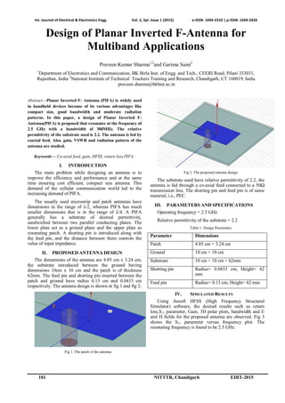
- 1. Int. Journal of Electrical & Electronics Engg. Vol. 2, Spl. Issue 1 (2015) e-ISSN: 1694-2310 | p-ISSN: 1694-2426 181 NITTTR, Chandigarh EDIT-2015 Design of Planar Inverted F-Antenna for Multiband Applications Praveen Kumar Sharma1,2 and Garima Saini2 1 Department of Electronics and Communication, BK Birla Inst. of Engg. and Tech., CEERI Road, Pilani 333031, Rajasthan, India 2 National Institute of Technical Teachers Training and Research, Chandigarh, UT 160019, India praveen.sharma@bkbiet.ac.in Abstract—Planar Inverted F- Antenna (PIFA) is widely used in handheld devices because of its various advantages like compact size, good bandwidth and moderate radiation patterns. In this paper, a design of Planar Inverted F- Antenna(PIFA) is proposed that resonates at the frequency of 2.5 GHz with a bandwidth of 300MHz. The relative permittivity of the substrate used is 2.2. The antenna is fed by coaxial feed. Also, gain, VSWR and radiation pattern of the antenna are studied. Keywords— Co-axial feed, gain, HFSS, return loss,PIFA. I. INTRODUCTION The main problem while designing an antenna is to improve the efficiency and performance and at the same time ensuring cost efficient, compact size antenna. This demand of the cellular communication world led to the increasing demand of PIFA. The usually used microstrip and patch antennas have dimensions in the range of λ/2, whereas PIFA has much smaller dimensions that is in the range of λ/4. A PIFA generally has a substrate of desired permittivity, sandwiched between two parallel conducting plates. The lower plate act as a ground plane and the upper plate as resonating patch. A shorting pin is introduced along with the feed pin, and the distance between them controls the value of input impedance. II. PROPOSED ANTENNA DESIGN The dimensions of the antenna are 4.85 cm x 3.24 cm, the substrate introduced between the ground having dimensions 10cm x 10 cm and the patch is of thickness 62mm. The feed pin and shorting pin inserted between the patch and ground have radius 0.13 cm and 0.0433 cm respectively. The antenna design is shown in fig 1 and fig 2. Fig 1. The patch of the antenna Fig 2. The proposed antenna design The substrate used have relative permittivity of 2.2, the antenna is fed through a co-axial feed connected to a 50Ω transmission line. The shorting pin and feed pin is of same material, i.e., PEC. III. PARAMETERS AND SPECIFICATIONS Operating frequency = 2.5 GHz Relative permittivity of the substrate = 2.2 Table 1. Design Parameters Parameter Dimensions Patch 4.85 cm × 3.24 cm Ground 10 cm × 10 cm Substrate 10 cm × 10 cm × 62mm Shorting pin Radius= 0.0433 cm, Height= 62 mm Feed pin Radius= 0.13 cm, Height= 62 mm IV. SIMULATED RESULTS Using Ansoft HFSS (High Frequency Structural Simulator) software, the desired results such as return loss,S11 parameter, Gain, 3D polar plots, bandwidth and E and H fields for the proposed antenna are observed. Fig 3 shows the S11 parameter versus frequency plot. The resonating frequency is found to be 2.5 GHz.
- 2. Int. Journal of Electrical & Electronics Engg. Vol. 2, Spl. Issue 1 (2015) e-ISSN: 1694-2310 | p-ISSN: 1694-2426 NITTTR, Chandigarh EDIT -2015 182 Fig 3. Return Loss versus Frquency Figure 4 and Figure 5 shows the 2D and 3D plot of the radiation pattern of the antenna. Fig 4. 2D Radiation Pattern Fig 5. 3D Radiation Pattern Figure 6 shows the VSWR plot versus frequency. Figure 7 and figure 8 shows the E and H field distribution on the patch. Fig 6. Plot for VSWR Fig 7. E- Field(vector) Distribution Fig 8.H-Field(vector) Distribution Figure 9 and figure 10 shows the input impedance and gain (rectangular plot) respectively. Fig. 9 Input Impedance
- 3. Int. Journal of Electrical & Electronics Engg. Vol. 2, Spl. Issue 1 (2015) e-ISSN: 1694-2310 | p-ISSN: 1694-2426 183 NITTTR, Chandigarh EDIT-2015 Fig 10. Rectangular Plot for Gain V. CALCULATED RESULTS Return Loss at 2.5 GHz = -2.60 dB Bandwidth of the antenna at -1 dB return loss = 300 MHz Maximum value of Gain = 28.5362, Phi = 0 deg and 24.6026, Phi = 90 deg. Frequency sweep = 2.54 GHz VI. CONCLUSION A PIFA is successfully designed supporting WLAN frequency resonating at 2.5 GHz, the desired WLAN frequency is achieved but other performance parameters such as return loss are not as per the requirements. So, optimization of size and design is required to obtain the same. However, further modifications in the design can make the antenna resonate at more than one frequency with desired outputs. REFERENCES [1] J. S. Chen,“Dual-frequency annular-ring slot antennas fed by a CPW feed and microstrip feed,” IEEE Trans. Antennas Propag. Lett., vol. 53, pp. 569–571, 2005. [2] W. C. Liu,“Design of a multiband CPW-fed monopole antenna using a particle swarm optimization approach” IEEE Trans. Antennas Propag., vol. 53, pp. 3273–3279, 2005. [3] Wen-Chung Liu, Chao-Ming Wu, and Yen-Jui Tseng “Parasitically Loaded CPW-Fed Monopole Antenna for Broadband Operation” IEEE Trans. Antennas and Propagation, Vol. 59, No. 6, 2011. [4] S. K. Oh, H. S. Yoon, and S. O. Park,“A PIFA-type varactor tunable slim antenna with a PIL patch feed for multiband applications” IEEE Antennas Wireless Propag. Lett., vol. 6, pp.103– 105, 2007. [5] A. Al-Zoubi, F.Yang, and A. Kishk,“A broadband center-fed circular patch-ring antenna with a monopole like radiation pattern” IEEE Trans. Antennas Propag., vol. 57, pp. 789–792, 2009. [6] Hassan Tariq Chattha, Yi Huang, Muhammad Kamran Ishfaq, Stephen J. Boyes, “A Comprehensive Parametric Study of Planar Inverted F- Antenna”, Wireless Engineering and Technology, Vol 3, January Edition, pp. 1-11, 2012. [7] Constantine G. Kakoyiannis and Philip Constantinou, “Compact, Slotted, Printed antenna For Dual-Band Communication in Future Wireless Sensor Network”, International Journal for Antenna and Propogation, Volume 2013. [8] Abdelhakim Elouadih, Ahmed Oulad-Said, Moha Mrabet Hassani, “Design and Parametric Simulation of a Miniaturized PIFA Antenna for the PCS Band”,Wireless Engineering and Technology, Volume 4, pp. 105-111, 2013. [9] V. P. Sarin, V. Deepu, C. K. Aanandan, P. Mohanan, and K.Vasudevan, “Wideband printed microstrip antenna for wireless communications,” IEEE Antennas Wireless Propag. Lett., vol. 8, pp. 779–781, 2009. [10] G. R. Aiello and G. D. Rogerson, “Ultra- wideband wireless system,” IEEE Microwave Mag., vol. 4, no. 2, pp. 36–47, Jun. 2003. [11] Kim, Y. and D. H. Kw on, “CPW-fed planar ultra wideband antenna having a frequency band notch function,” Electronics Letters, Vol.40, No.7, 403– 405, 2004.