SlideShare a Scribd company logo
1 of 9
Download to read offline
Available online at www.sciencedirect.com
Journal of Applied Research
and Technology
www.jart.ccadet.unam.mx
Journal of Applied Research and Technology 13 (2015) 526–534
Original
Design of triple-layer double U-slot patch antenna for wireless applications
Naresh Kumar Darimireddya,∗, R. Ramana Reddyb, A. Mallikarjuna Prasadc
a Department of ECE, Lendi Institute of Engineering & Technology, Vizianagaram, AP, India
b Department of ECE, MVGR College of Engineering, Vizianagaram, AP, India
c Department of ECE, UCEK, JNTUK, Kakinada, India
Received 21 March 2015; accepted 21 September 2015
Available online 26 October 2015
Abstract
Many techniques have been proposed to design microstrip patch antennas with multiband characteristics. In the proposed antenna design, a
combination of dual U-slot and multiple layers is used to get multiple bands and wide bandwidth. A multiband triple-layer probe fed double U-slot
microstrip patch antenna for next generation wireless applications is proposed in this paper. Parametric studies of antenna structure with double
U-slot, variation of feed position, and also with multiple layers are presented. The proposed antenna is fabricated and tested. The simulation and
experimental results are presented. The proposed antenna provides triple bands at 1.6 GHz, 1.9 GHz and 3.8 GHz and a bandwidth of 600 MHz for
a substrate thickness of 1.6 mm and 1.8 GHz, 2.2 GHz and 4.8 GHz and a bandwidth of 800 MHz for a substrate of 0.6 mm thickness.
All Rights Reserved © 2015 Universidad Nacional Autónoma de México, Centro de Ciencias Aplicadas y Desarrollo Tecnológico. This is an
open access item distributed under the Creative Commons CC License BY-NC-ND 4.0.
Keywords: Triple-layer structure; Microstrip antenna; Probe feed; Multiband; Slot antenna
1. Introduction
The rapid expansion and revolution of wireless technology
has drawn new demands for integrated components including
antennas. Antenna is one of the main components of the inte-
grated low-profile wireless communication systems; therefore,
antennas miniaturization is necessary to achieve the optimal
design. Some wireless applications of antennas are desired to
operate simultaneously for Wireless LAN, Worldwide Inter-
operability for Microwave Access (WiMAX) and some next
generation wireless technologies.
The basic geometry and configuration of the U-slot antenna
was introduced in 1995 by Huynh and Lee as a single-
layer, single-patch wideband linearly polarized microstrip patch
antenna. Multiband antennas (Lee, Luk, Mak, & Yang, 2011)
can cover multiple wireless technologies; however, in microstrip
patch antennas, the U-slot was mainly used for bandwidth
enhancement rather than introducing a band notch and it has
∗ Corresponding author.
E-mail address: yojitnaresh@gmail.com (N.K. Darimireddy).
Peer Review under the responsibility of Universidad Nacional Autónoma de
México.
been shown that the U-slot technique can be used to design patch
antennas with dual and multi-band characteristics. The studies
reported (Lee, Steven Yang, Kishk, & Luk, 2010; Singh, Ali,
Singh, & Ayub, 2013) on U-slot patch antenna showed that, it
can be intended not only for wideband applications, but also
for multiband (dual and triple-band) applications. It is even
more complex to integrate multiple bands for wireless tech-
nologies (Vedaprabhu & Vinoy, 2010) such as AWS (Advanced
Wireless Services), GSM (Global System for Mobile) and var-
ious WiMAX and WLAN bands operating at several frequency
ranges. Design of multi-band microstrip patch antennas even
with narrow bandwidths is challenging. Patch antennas with
properly designed slits or slots are useful in this perspective.
Bandwidth can be increased at the cost of size of the patch. To
overcome this problem, a multiple layer dielectric substrate has
been used to improve the bandwidth (Rao & Kumar, 2011). The
multi layer structure not only offers the enhanced impedance
bandwidth but also possesses the same characteristics over
desired frequency band (Kushwah, Dubey, & Singhal, 2006).
The techniques such as multilayer microstrip antennas using
low dielectric constant substrate improve the impedance band-
width and multiple (Ghassemi, Neshati, & Rashed-Mohassel,
2007) frequency band of operation. Design of multilayer stacked
http://dx.doi.org/10.1016/j.jart.2015.10.006
1665-6423/All Rights Reserved © 2015 Universidad Nacional Autónoma de México, Centro de Ciencias Aplicadas y Desarrollo Tecnológico. This is an open access
item distributed under the Creative Commons CC License BY-NC-ND 4.0.
N.K. Darimireddy et al. / Journal of Applied Research and Technology 13 (2015) 526–534 527
patch antennas provides bandwidths for broadband applica-
tions (Hoorfar, 1992). The two resonant frequencies approach
each other when the (Lee & Nalbandian, 1993) air gap length
increases. The resonant behavior can be considered as a coupling
between two resonating modes in the dielectric regions through
the air gap.
Many works had reported on the design of low-profile multi-
band antennas. In this paper design of triple-layer double U-slot
patch antenna is proposed to get multiple bands and wide band-
width.
2. Antenna design and configuration
Many researchers reported design of microstrip patch anten-
nas based on either incorporating slots or introducing multiple
layers. Design of the proposed antenna is a combination of dou-
ble U-slot and multilayer structure with air gap as one of the
layer. To design coaxial probe feed rectangular patch antennas,
there are some essential parameters to be considered. Firstly, the
resonant frequency (f0) of the antenna must be selected appropri-
ately.Thedimensionsofthemicrostrippatchantennaarederived
at the center frequency of f0 (Balanis, 2005) using Eq. (1). The
Return Loss (RL) and VSWR values are calculated using Eqs.
(2) and (3).
f0 =
C
2L
√
∈ reff
(1)
where L is the length of the patch, C is the velocity of light in
free space and ∈ reff is an effective dielectric constant.
RL = −10 log

Pr
Pi

or RL = −20 log(Γ ) dB (2)
where Pi is an incident power; Pr is the reflected power and Ŵ
is the reflection coefficient.
VSWR =
Vmax
Vmin
=
1 + |Γ |
1 − |Γ |
(3)
The dielectric material of FR-4 Epoxy with 1.6 mm thickness
is selected for this design and has a dielectric constant of 4.4(εr)
and loss tangent equal to 0.002. Low dielectric constant is used in
the prototype design because it gives better efficiency and higher
bandwidth (Balanis, 2005; Ramesh, Prakash, Inder,  Apisak,
2001; Wong, 2002) and it increases the fringing field at the patch
periphery and thus increases the radiated power. The small loss
tangent was neglected in the simulation. Substrate thickness is
another important design parameter. Thick substrate increases
the fringing field at the patch periphery like low dielectric con-
stant and thus increases the radiated power (Kraus, 1988; Raju,
2005).
The proposed antenna is simulated using HFSS and the prac-
tical results are obtained by testing the fabricated antenna using
Vector Network Analyzer (E5071C). The design of single U-
slot antenna structure is presented in Fig. 1 and corresponding
dimensions are length of the patch (L) is 52 mm, width of the
patch (W) is 71 mm, length of vertical outer slot (ls1) is 40 mm,
length of horizontal outer U-slot (bs1) is 18 mm, width of outer
slot (ws1) is 4 mm, and offset feed length (d) is 9 mm.
L
W
Ws1
Is1
bs1
d
Y
X
Fig. 1. Structure of the antenna with single or primary U-slot.
2.1. Simulated results of single U-slot structure
Initially a single or primary U-slot is introduced on the patch
as shown in Fig. 1 and the simulation results are shown in Fig. 2.
• Return Loss
Fig. 2 shows the S11 versus frequency plot. The antenna with
primary U-slot resonates at the frequency 2.5 GHz.
One more U-slot (secondary U-slot) is introduced inside the
primary U-slot. The dimensions of the secondary U-slot are
ls2 = 13 mm, bs2 = 4 mm, and ws2 = 1 mm as shown in Fig. 3.
2.2. Simulated results of double U-slot structure
The patch antenna with primary U-slot resonates at single
frequency. The introduction of secondary U-slot as shown in
Fig. 3 provides dual band frequencies.
• Return Loss
Fig. 4 shows the Return Loss curve of double U-slot structure.
It is observed that the incorporation of secondary U-slot gives
dual resonant frequencies at 1.9 GHz and 5.5 GHz.
2.3. Simulation of results by varying offset position (d)
Feed position plays a major role in the design. Probe feed
is used to provide the feed to the antenna. The characteris-
tics of antenna vary with the probe position from center of the
patch toward secondary U-slot and the corresponding results are
tabulated in Table 1.
• Return Loss
Fig. 5 shows the Return Loss curve when the feed position
is at center (d = 0). It is observed that the resonant frequency is
2 GHz when feed is at the center.
528 N.K. Darimireddy et al. / Journal of Applied Research and Technology 13 (2015) 526–534
1.00
0.00
–2.00
–4.00
–6.00
–8.00
–10.00
–12.00
–14.00
2.00 3.00 4.00 5.00 6.00
Freq [GHz]
W
XY Plot 1 Patch_Antenna_ADKv1
dB(St(coax_pin_T1,coax_pin_T1))
7.00 8.00 9.00 10.00
Curve info
dB(St(coax_pin_T1,coax_pin_T1))
Setup1: Sweep
Fig. 2. Return Loss of the single U-slot structure.
L
W
Ws1
Is1
Is2
X
Y
bs1
bs2
Ws2
d
Fig. 3. Structure of the antenna with double or secondary U-slot.
Table 1
Variation of gain and frequency with feed position.
Offset feed (d)
Position (mm)
Gain (dB) ResonantFrequencies (GHz)
At center (d = 0) 5.34 2
Moving downwards (d = 1) 5.41 2, 3.1
Moving downwards (d = 4) 5.63 2.2, 4.8
Moving downwards (d = 9) 6.80 1.9, 2.1, 5.4
The observations from the Figs. 4 and 5 and Table 1 are that
the primary U-slot gives single band, secondary U-slot provides
two bands and multiple bands are obtained for offset feed posi-
tion (d = 9) with a gain of 6.80 dB. The gain is increasing with
increase in offset feed position (d) as shown in Table 1.
3. Triple-layer structure of the proposed antenna
The proposed design of the antenna is a combination of two
U-slots and triple-layer structure as shown in Fig. 6. The height
of dielectric substrate employed in this design of antenna is
h = 1.6 mm for top and bottom layers. The middle layer among
the three layers is taken as air and the gap between first and third
layers is taken as 8.5 mm.
1.00
0.00
–2.00
–4.00
–6.00
–8.00
–10.00
–12.00
–14.00
–16.00
2.00 3.00 4.00 5.00 6.00
Freq [GHz]
XY Plot 1 Patch_Antenna_ADKv1
dB(St(coax_pin_T1,coax_pin_T1))
7.00 8.00 9.00 10.00
Curve info
dB(St(coax_pin_T1,coax_pin_T1))
Setup1: Sweep
Fig. 4. Return Loss of double U-slot structure.
N.K. Darimireddy et al. / Journal of Applied Research and Technology 13 (2015) 526–534 529
1.00
0.00
–2.00
–4.00
–6.00
–8.00
–10.00
–12.00
2.00 3.00 4.00 5.00 6.00
Freq [GHz]
XY Plot 1
dB(St(coax_pin_T1,coax_pin_T1))
7.00 8.00 9.00 10.00
Patch_Antenna_ADKv1
Curve info
dB(St(coax_pin_T1,coax_pin_T1))
Setup1: Sweep
Fig. 5. Return Loss when feed position is d = 0.
Fig. 6. Probe fed triple-layer structure of the proposed antenna.
Table 2
Comparison of gain values with substrate material and number of layers.
Substrate material Gain (dB)
(Triple-layer)
Gain (dB)
(Single layer)
Arlon 7.4742 6.8016
Dupont 7.5634 5.7975
FR4 6.5829 3.6454
Nelco 7.4161 5.6314
Neltec 7.5869 5.8316
Taconic 7.6323 6.1268
Diamond pl cvd 7.6948 6.7759
Polymide 7.5561 6.3556
4. Parametric study and discussion of results
4.1. Variation of substrate material
• Return Loss
Fig. 7 shows the S11 versus frequency plot of triple-
layer structure. The effect on gain with respect to single and
triple-layer is tabulated in Table 2 along with variation of sub-
strate material.
From Table 2 it is observed that the triple-layer structure
possesses increased gain around 7.5 dB for various substrate
materials like Arlon, Diamond pl cvd and polymide, etc. Due to
the non-availability and high cost of the materials, the proposed
antenna is fabricated using FR4 substrate material.
4.2. Variation of gap between primary and secondary
U-slots
• Return Loss
Fig. 8 shows the Return Loss of the antenna when the gap is
5 mm and the obtained dual band frequencies are 2.2 GHz and
4.2 GHz. The effect of gain and corresponding resonant frequen-
cies are tabulated in Table 3 with the variation of gap between
primary and secondary U-slots.
From Table 3 it is observed that when the gap is reduced from
5 mm to 1 mm successively the gain is varied around 6.6–7.5 dB
and provides multiple bands at various gap dimensions.
530 N.K. Darimireddy et al. / Journal of Applied Research and Technology 13 (2015) 526–534
1.00
0.00
–2.00
–4.00
–6.00
–8.00
–10.00
–12.00
–14.00
2.00 3.00 4.00 5.00 6.00
Freq [GHz]
XY Plot 1
dB(St(coax_pin_T1,coax_pin_T1))
7.00 8.00 9.00 10.00
Patch_Antenna_ADKv1
Curve info
dB(St(coax_pin_T1,coax_pin_T1))
Setup1: Sweep
Fig. 7. Return Loss plot for triple-layer structure.
1.00
0.00
–2.00
–4.00
–6.00
–8.00
–10.00
–12.00
–14.00
–16.00
–18.00
2.00 3.00 4.00 5.00 6.00
Freq [GHz]
XY Plot 1
dB(St(coax_pin_T1,coax_pin_T1))
7.00 8.00 9.00 10.00
Patch_Antenna_ADKv1
Curve info
dB(St(coax_pin_T1,coax_pin_T1))
Setup1: Sweep
Fig. 8. Return Loss when gap between primary and secondary U-slots is 5 mm.
Table 3
Effect of gain and resonant frequencies with variation of gap between two U-
slots.
Gap (mm) Gain (dB) Resonant
Frequencies (GHz)
5 6.61 2.2, 4.2
4 6.42 2.1, 4.4
3 7.21 2.2, 4.5, 5.7
2 6.81 2.1, 4.8, 5.4
4.3. Variation of double U-slot structure position on
substrate
VaryingthedoubleU-slotstructurepositiononsubstratefrom
center of the substrate to both upward and downward directions,
and by keeping the optimum values of length, feed position,
substrate material and gap between U-slots, the following results
are obtained.
• Return Loss
Table 4
Effect of double U-slot structure position with respect to substrate and corre-
sponding gain and resonant frequencies.
Gap (mm) Gain (dB) Resonant
Frequencies (GHz)
16.00 7.66 2.2, 5.9
15.00 7.34 2.2, 4.4, 5.7
14.75 7.17 1.8, 2.2, 5.6
14.50 7.53 2.2, 4.5, 6.0
14.25 7.46 2.24, 4.5, 5.6
13.75 7.15 2.2, 4.5, 5.6
13.50 7.14 2.2, 4.8
13.00 6.81 2.2, 4.4
12.00 6.60 2.2, 4.7
Fig. 9 shows the Return Loss of the antenna when the gap
between patch (primary slot) and bottom edge of substrate
(shifted 2 mm downwards) is 12 mm.
From Table 4 it is observed that when the gap increases the
gain improved and in the same way multiple (triple and double)
frequency bands are obtained.
N.K. Darimireddy et al. / Journal of Applied Research and Technology 13 (2015) 526–534 531
1.00
2.50
–7.50
–10.00
–12.50
–15.00
–17.50
–20.00
–2.50
–5.00
0.00
2.00 3.00 4.00 5.00 6.00
Freq [GHz]
XY Plot 1
dB(St(coax_pin_T1,coax_pin_T1))
7.00 8.00 9.00 10.00
Patch_Antenna_ADKv1
Curve info
dB(St(coax_pin_T1,coax_pin_T1))
Setup1: Sweep
Fig. 9. Return Loss plot when the patch is shifted 2 mm downwards.
1.00 2.00 3.00 4.00 5.00 6.00
Freq [GHz]
XY Plot 4
7.00 8.00 9.00 10.00
–2.50
–7.50
–10.00
–12.50
–15.00
–17.50
–5.00
0.00
dB(St(coax_pin_T1,coax_pin_T1))
Patch_Antenna_ADKv1
Curve info
dB(St(coax_pin_T1,coax_pin_T1))
Setup1: Sweep
Fig. 10. Simulated Return Loss for 0.6 mm substrate thickness.
4.4. Simulated results of variable substrate thickness
Varying the thickness of the substrate for top and bottom
layers, the dual-band and sufficient impedance bandwidth
characteristics are obtained. The optimum thickness of the
substrate is 0.6 mm. But practically, fabrication of antenna with
such less thickness is complex, so the thickness of 1.6 mm is
considered. Figs. 10 and 11 show the Return Loss of antenna
with thickness of 0.6 mm and 1.6 mm respectively.
• Return Loss
From Fig. 10 the Return Loss is −17.41 dB at 1.8 GHz,
−17.42 dB at 2.2 GHz and −12.1 dB at 4.8 GHz. The impedance
1.00
–7.50
Name
m1
m2
m3
X
1.6000
1.9000
3.8000
Y
–10.7948
–15.9132
–20.1501
m1
m2
–12.50
–17.50
–22.50
2.00 3.00 4.00 5.00 6.00
Freq [GHz]
XY Plot 1
dB(St(coax_pin_T1,coax_pin_T1))
7.00 8.00 9.00 10.00
m3
Patch_Antenna_ADKv1
Curve info
dB(St(coax_pin_T1,coax_pin_T1))
Setup1: Sweep
Fig. 11. Simulated Return Loss for 1.6 mm substrate thickness.
532 N.K. Darimireddy et al. / Journal of Applied Research and Technology 13 (2015) 526–534
1.00
80.00
60.00
40.00
20.00
0.00
m1 m2 m3
2.00 3.00 4.00 5.00 6.00
Freq [GHz]
XY Plot 2
7.00 8.00 9.00 10.00
Patch_Antenna_ADKv1
Curve info
VSWRt(coax_pin_T1)
Setup1: Sweep
VSWRt(coax_pin_T1)Name
m1
m2
m3
X
1.6000
1.9000
3.8000
Y
1.8113
1.3814
1.2180
Fig. 12. Simulated VSWR plot.
Fig. 13. Fabricated structure of the patch.
bandwidth obtained is 800 MHz with substrate thickness of
0.6 mm. From Fig. 11 it is observed that with substrate thick-
ness of 1.6 mm the resonant frequencies of 1.6 GHz, 1.9 GHz
and 3.8 GHz are obtained.
• VSWR
Fig. 12 shows that the VSWR values of the proposed antenna
are 1.8113 at 1.6 GHz, 1.3814 at 1.9 GHz and 1.2180 at 3.8 GHz.
Fig. 14. Fabricated structure of ground.
Fig. 15. Side view of triple-layer fabricated antenna.
From Figs. 10 and 11 it is observed that, with the variation
of substrate thickness triple bands are obtained with improved
bandwidth. It is difficult to provide the substrate with 0.6 mm
thickness, so the design of antenna is carried out with substrate
thickness of 1.6 mm. Fig. 12 shows that the VSWR is lesser than
2 at consequent resonant frequencies.
5. Fabricated structure and practical results
The fabricated antenna with three layers is shown in
Figs. 13–15 with patch and ground planes. Fig. 16 shows the
experimental setup with Vector Network Analyzer (VNA).
Fig. 16. Experimental setup of fabricated antenna.
N.K. Darimireddy et al. / Journal of Applied Research and Technology 13 (2015) 526–534 533
Fig. 17. Return Loss of fabricated antenna.
Fig. 18. VSWR graph of fabricated antenna.
• Return Loss
Fig. 17 shows the Return Loss curve of fabricated antenna
displayed on VNA. The obtained simulated resonant frequen-
cies are 1.6 GHz, 1.9 GHz and 3.8 GHz. The tested results of
fabricated antenna with Vector Network Analyzer (VNA) are
nearly same as the simulated results and they are 1.54 GHz,
1.89 GHz and 3.81 GHz. The obtained impedance bandwidth
of fabricated antenna is 600 MHz from 3.6 GHz to 4.2 GHz at
center frequency 3.8 GHz.
534 N.K. Darimireddy et al. / Journal of Applied Research and Technology 13 (2015) 526–534
• VSWR
Fig. 18 shows that the VSWR values at 1.54 GHz, 1.9 GHz
and 3.78 GHz are 1.906, 1.722 and 1.909 respectively.
6. Conclusions
The design of multilayer microstrip patch antenna has been
proposed in this paper. The proposed triple-layer structure of
the antenna can be used for multiple wireless applications. The
inclusion of three layers in the antenna structure increases the
bandwidth and it leads to the more coverage of frequencies. The
proposed triple-layer double U-slot patch antenna is simulated
in HFSS solver and fabricated using thermo-lithography pro-
cess. It is observed from the extensive parametric study that the
antennapossessestriplebandsinmostofthecases.Theproposed
antenna has triple bands at 1.6 GHz, 1.9 GHz and 3.8 GHz and
a bandwidth of 600 MHz. The experimental results are in close
agreement with the simulated results.
Conflict of interest
The authors have no conflicts of interest to declare.
References
Balanis, C. A. (2005). Antenna theory analysis and design (3rd ed.). Wiley
Publication.
Ghassemi, N., Neshati, M. H.,  Rashed-Mohassel, J. (2007). Investigation of
multi layer probe-fed microstrip antenna for ultra wideband operation. In
Proceedings of Asia-Pacific microwave conference IEEE.
Hoorfar, A. (1992). Accurate modeling of multi-layer microstrip antennas. In
Proceedings of Asia-Pacific microwave conference Adelaide, IEEE, (pp.
207–210).
Huynh, T.,  Lee, K.-F. (1995). Single-layer single-patch wideband microstrip
antenna. Electronics Letters, 1310–1312.
Kraus, J. D. (1988). Antennas (2nd ed.). New York, NY: McGraw-Hill.
Kushwah, R. P. S., Dubey, M.,  Singhal, P. K. (2006). Design of a triple layer
microstrip patch antenna. In 2006 IEEE international workshop on antenna
technology, IWAT 2006 – Small antennas and novel metamaterials, 2006
(pp. 49–52).
Lee, C. S.,  Nalbandian, V. (1993). Impedance matching of a dual-frequency
microstrip antenna with an air gap. IEEE Transactions on Antennas and
Propagation, 41(5), 680–682.
Lee, K. F., Luk, K. M., Mak, K. M.,  Yang, S. L. S. (2011). On the use of U-
slots in the design of dual- and triple-band patch antennas. IEEE Antennas
and Propagation Magazine, 53(3), 60–74.
Lee, K. F., Steven Yang, S. L., Kishk, A. A.,  Luk, K. M. (2010). The versatile
U-slot patch antenna. IEEE Antennas and Propagation Magazine, 52(1),
71–88.
Raju, G. S. N. (2005). Antennas and wave propagation. New Delhi: Pearson
Education (Singapore) Pvt. Ltd.
Ramesh, G., Prakash, B., Inder, B.,  Apisak, I. (2001). Microstrip antenna
design handbook. Boston, London: Artech House Publications.
Rao, N.,  Kumar, V. D. (2011). Gain and bandwidth enhancement of a
microstrip antenna using partial substrate removal in multiple-layer dielec-
tricsubstrate.InProgresselectromagneticsresearchsymposiumproceedings
Suzhou, China, (pp. 1285–1289).
Singh, V. K., Ali, Z., Singh, A. K.,  Ayub, S. (2013). Dual band microstrip
antenna for UMTS/WLAN/WIMAX applications. In 2013 international
conference on communication systems and network technologies (CSNT).
IEEE (pp. 47–50).
Vedaprabhu, B.,  Vinoy, K. J. (2010). An integrated wideband multifunctional
antenna using a micro strip patch with two U-slots. Progress in Electromag-
netics Research B, 22, 221–235.
Wong, K. L. (2002). Compact and broadband microstrip antennas. Wiley Pub-
lication.

More Related Content

Similar to S1665642315000577.pdf

Design of Square Miniaturized L Band Fractal Antenna
Design of Square Miniaturized L Band Fractal AntennaDesign of Square Miniaturized L Band Fractal Antenna
Design of Square Miniaturized L Band Fractal AntennaEditor IJMTER
 
A Wideband Circularly Polarized Printed Monopole Antenna with Symmetric Groun...
A Wideband Circularly Polarized Printed Monopole Antenna with Symmetric Groun...A Wideband Circularly Polarized Printed Monopole Antenna with Symmetric Groun...
A Wideband Circularly Polarized Printed Monopole Antenna with Symmetric Groun...IRJET Journal
 
Microstrip Rectangular Monopole Antennas with Defected Ground for UWB Applica...
Microstrip Rectangular Monopole Antennas with Defected Ground for UWB Applica...Microstrip Rectangular Monopole Antennas with Defected Ground for UWB Applica...
Microstrip Rectangular Monopole Antennas with Defected Ground for UWB Applica...IJECEIAES
 
A CPW-Fed Wideband And Multiband Rectangular Microstrip Patch Antenna For Wir...
A CPW-Fed Wideband And Multiband Rectangular Microstrip Patch Antenna For Wir...A CPW-Fed Wideband And Multiband Rectangular Microstrip Patch Antenna For Wir...
A CPW-Fed Wideband And Multiband Rectangular Microstrip Patch Antenna For Wir...IJMER
 
A Hepta-Band Antenna For Wireless Applications
A Hepta-Band Antenna For Wireless ApplicationsA Hepta-Band Antenna For Wireless Applications
A Hepta-Band Antenna For Wireless Applicationsdbpublications
 
Gain Enhancement of Series Feed Square Patch Microstrip Antenna Array for S b...
Gain Enhancement of Series Feed Square Patch Microstrip Antenna Array for S b...Gain Enhancement of Series Feed Square Patch Microstrip Antenna Array for S b...
Gain Enhancement of Series Feed Square Patch Microstrip Antenna Array for S b...ijsrd.com
 
Study of Compact and Wideband Microstrip U-Slot Patch Antenna with DGS for Sa...
Study of Compact and Wideband Microstrip U-Slot Patch Antenna with DGS for Sa...Study of Compact and Wideband Microstrip U-Slot Patch Antenna with DGS for Sa...
Study of Compact and Wideband Microstrip U-Slot Patch Antenna with DGS for Sa...Rammohan Mudgal
 
Design and Analysis of Single Microstrip Patch Antenna with Proximity Coupler...
Design and Analysis of Single Microstrip Patch Antenna with Proximity Coupler...Design and Analysis of Single Microstrip Patch Antenna with Proximity Coupler...
Design and Analysis of Single Microstrip Patch Antenna with Proximity Coupler...IOSR Journals
 
Multiband antenna using stacked series array for Ka-Band application
Multiband antenna using stacked series array for Ka-Band applicationMultiband antenna using stacked series array for Ka-Band application
Multiband antenna using stacked series array for Ka-Band applicationjournalBEEI
 
Microstrip Antenna Design For Ultra-Wide Band Applications
Microstrip Antenna Design For Ultra-Wide Band ApplicationsMicrostrip Antenna Design For Ultra-Wide Band Applications
Microstrip Antenna Design For Ultra-Wide Band Applicationsinventionjournals
 
Design of a Dual-Band Microstrip Patch Antenna for GPS,WiMAX and WLAN
Design of a Dual-Band Microstrip Patch Antenna for GPS,WiMAX and WLANDesign of a Dual-Band Microstrip Patch Antenna for GPS,WiMAX and WLAN
Design of a Dual-Band Microstrip Patch Antenna for GPS,WiMAX and WLANIOSR Journals
 
Design of a Dual-Band Microstrip Patch Antenna for GPS,WiMAX and WLAN.
Design of a Dual-Band Microstrip Patch Antenna for GPS,WiMAX and WLAN.Design of a Dual-Band Microstrip Patch Antenna for GPS,WiMAX and WLAN.
Design of a Dual-Band Microstrip Patch Antenna for GPS,WiMAX and WLAN.IOSR Journals
 
Microstrip patch antenna for pcs and wlan
Microstrip patch antenna for pcs and wlanMicrostrip patch antenna for pcs and wlan
Microstrip patch antenna for pcs and wlaneSAT Journals
 
Miniaturised tri-band microstrip patch antenna design for radio and millimet...
Miniaturised tri-band microstrip patch antenna design for  radio and millimet...Miniaturised tri-band microstrip patch antenna design for  radio and millimet...
Miniaturised tri-band microstrip patch antenna design for radio and millimet...nooriasukmaningtyas
 

Similar to S1665642315000577.pdf (20)

Design of Square Miniaturized L Band Fractal Antenna
Design of Square Miniaturized L Band Fractal AntennaDesign of Square Miniaturized L Band Fractal Antenna
Design of Square Miniaturized L Band Fractal Antenna
 
A Wideband Circularly Polarized Printed Monopole Antenna with Symmetric Groun...
A Wideband Circularly Polarized Printed Monopole Antenna with Symmetric Groun...A Wideband Circularly Polarized Printed Monopole Antenna with Symmetric Groun...
A Wideband Circularly Polarized Printed Monopole Antenna with Symmetric Groun...
 
Microstrip Rectangular Monopole Antennas with Defected Ground for UWB Applica...
Microstrip Rectangular Monopole Antennas with Defected Ground for UWB Applica...Microstrip Rectangular Monopole Antennas with Defected Ground for UWB Applica...
Microstrip Rectangular Monopole Antennas with Defected Ground for UWB Applica...
 
A CPW-Fed Wideband And Multiband Rectangular Microstrip Patch Antenna For Wir...
A CPW-Fed Wideband And Multiband Rectangular Microstrip Patch Antenna For Wir...A CPW-Fed Wideband And Multiband Rectangular Microstrip Patch Antenna For Wir...
A CPW-Fed Wideband And Multiband Rectangular Microstrip Patch Antenna For Wir...
 
A Hepta-Band Antenna For Wireless Applications
A Hepta-Band Antenna For Wireless ApplicationsA Hepta-Band Antenna For Wireless Applications
A Hepta-Band Antenna For Wireless Applications
 
H0524548
H0524548H0524548
H0524548
 
Gain Enhancement of Series Feed Square Patch Microstrip Antenna Array for S b...
Gain Enhancement of Series Feed Square Patch Microstrip Antenna Array for S b...Gain Enhancement of Series Feed Square Patch Microstrip Antenna Array for S b...
Gain Enhancement of Series Feed Square Patch Microstrip Antenna Array for S b...
 
Study of Compact and Wideband Microstrip U-Slot Patch Antenna with DGS for Sa...
Study of Compact and Wideband Microstrip U-Slot Patch Antenna with DGS for Sa...Study of Compact and Wideband Microstrip U-Slot Patch Antenna with DGS for Sa...
Study of Compact and Wideband Microstrip U-Slot Patch Antenna with DGS for Sa...
 
Design and Analysis of Single Microstrip Patch Antenna with Proximity Coupler...
Design and Analysis of Single Microstrip Patch Antenna with Proximity Coupler...Design and Analysis of Single Microstrip Patch Antenna with Proximity Coupler...
Design and Analysis of Single Microstrip Patch Antenna with Proximity Coupler...
 
H010124449
H010124449H010124449
H010124449
 
H010435256
H010435256H010435256
H010435256
 
Dual U-Slot Microstrip Patch Antenna with Enhanced Bandwidth
Dual U-Slot Microstrip Patch Antenna with Enhanced BandwidthDual U-Slot Microstrip Patch Antenna with Enhanced Bandwidth
Dual U-Slot Microstrip Patch Antenna with Enhanced Bandwidth
 
Multiband antenna using stacked series array for Ka-Band application
Multiband antenna using stacked series array for Ka-Band applicationMultiband antenna using stacked series array for Ka-Band application
Multiband antenna using stacked series array for Ka-Band application
 
Microstrip Antenna Design For Ultra-Wide Band Applications
Microstrip Antenna Design For Ultra-Wide Band ApplicationsMicrostrip Antenna Design For Ultra-Wide Band Applications
Microstrip Antenna Design For Ultra-Wide Band Applications
 
Design of a Dual-Band Microstrip Patch Antenna for GPS,WiMAX and WLAN
Design of a Dual-Band Microstrip Patch Antenna for GPS,WiMAX and WLANDesign of a Dual-Band Microstrip Patch Antenna for GPS,WiMAX and WLAN
Design of a Dual-Band Microstrip Patch Antenna for GPS,WiMAX and WLAN
 
Design of a Dual-Band Microstrip Patch Antenna for GPS,WiMAX and WLAN.
Design of a Dual-Band Microstrip Patch Antenna for GPS,WiMAX and WLAN.Design of a Dual-Band Microstrip Patch Antenna for GPS,WiMAX and WLAN.
Design of a Dual-Band Microstrip Patch Antenna for GPS,WiMAX and WLAN.
 
Microstrip patch antenna for pcs and wlan
Microstrip patch antenna for pcs and wlanMicrostrip patch antenna for pcs and wlan
Microstrip patch antenna for pcs and wlan
 
Ac4101168171
Ac4101168171Ac4101168171
Ac4101168171
 
Ring Shape Micro-Strip Patch Antenna For UWB Applications
Ring Shape Micro-Strip Patch Antenna For UWB ApplicationsRing Shape Micro-Strip Patch Antenna For UWB Applications
Ring Shape Micro-Strip Patch Antenna For UWB Applications
 
Miniaturised tri-band microstrip patch antenna design for radio and millimet...
Miniaturised tri-band microstrip patch antenna design for  radio and millimet...Miniaturised tri-band microstrip patch antenna design for  radio and millimet...
Miniaturised tri-band microstrip patch antenna design for radio and millimet...
 

Recently uploaded

Strategize a Smooth Tenant-to-tenant Migration and Copilot Takeoff
Strategize a Smooth Tenant-to-tenant Migration and Copilot TakeoffStrategize a Smooth Tenant-to-tenant Migration and Copilot Takeoff
Strategize a Smooth Tenant-to-tenant Migration and Copilot Takeoffsammart93
 
How to Troubleshoot Apps for the Modern Connected Worker
How to Troubleshoot Apps for the Modern Connected WorkerHow to Troubleshoot Apps for the Modern Connected Worker
How to Troubleshoot Apps for the Modern Connected WorkerThousandEyes
 
Artificial Intelligence Chap.5 : Uncertainty
Artificial Intelligence Chap.5 : UncertaintyArtificial Intelligence Chap.5 : Uncertainty
Artificial Intelligence Chap.5 : UncertaintyKhushali Kathiriya
 
Rising Above_ Dubai Floods and the Fortitude of Dubai International Airport.pdf
Rising Above_ Dubai Floods and the Fortitude of Dubai International Airport.pdfRising Above_ Dubai Floods and the Fortitude of Dubai International Airport.pdf
Rising Above_ Dubai Floods and the Fortitude of Dubai International Airport.pdfOrbitshub
 
"I see eyes in my soup": How Delivery Hero implemented the safety system for ...
"I see eyes in my soup": How Delivery Hero implemented the safety system for ..."I see eyes in my soup": How Delivery Hero implemented the safety system for ...
"I see eyes in my soup": How Delivery Hero implemented the safety system for ...Zilliz
 
Vector Search -An Introduction in Oracle Database 23ai.pptx
Vector Search -An Introduction in Oracle Database 23ai.pptxVector Search -An Introduction in Oracle Database 23ai.pptx
Vector Search -An Introduction in Oracle Database 23ai.pptxRemote DBA Services
 
Six Myths about Ontologies: The Basics of Formal Ontology
Six Myths about Ontologies: The Basics of Formal OntologySix Myths about Ontologies: The Basics of Formal Ontology
Six Myths about Ontologies: The Basics of Formal Ontologyjohnbeverley2021
 
Spring Boot vs Quarkus the ultimate battle - DevoxxUK
Spring Boot vs Quarkus the ultimate battle - DevoxxUKSpring Boot vs Quarkus the ultimate battle - DevoxxUK
Spring Boot vs Quarkus the ultimate battle - DevoxxUKJago de Vreede
 
Polkadot JAM Slides - Token2049 - By Dr. Gavin Wood
Polkadot JAM Slides - Token2049 - By Dr. Gavin WoodPolkadot JAM Slides - Token2049 - By Dr. Gavin Wood
Polkadot JAM Slides - Token2049 - By Dr. Gavin WoodJuan lago vázquez
 
AI in Action: Real World Use Cases by Anitaraj
AI in Action: Real World Use Cases by AnitarajAI in Action: Real World Use Cases by Anitaraj
AI in Action: Real World Use Cases by AnitarajAnitaRaj43
 
WSO2's API Vision: Unifying Control, Empowering Developers
WSO2's API Vision: Unifying Control, Empowering DevelopersWSO2's API Vision: Unifying Control, Empowering Developers
WSO2's API Vision: Unifying Control, Empowering DevelopersWSO2
 
DBX First Quarter 2024 Investor Presentation
DBX First Quarter 2024 Investor PresentationDBX First Quarter 2024 Investor Presentation
DBX First Quarter 2024 Investor PresentationDropbox
 
Finding Java's Hidden Performance Traps @ DevoxxUK 2024
Finding Java's Hidden Performance Traps @ DevoxxUK 2024Finding Java's Hidden Performance Traps @ DevoxxUK 2024
Finding Java's Hidden Performance Traps @ DevoxxUK 2024Victor Rentea
 
Exploring Multimodal Embeddings with Milvus
Exploring Multimodal Embeddings with MilvusExploring Multimodal Embeddings with Milvus
Exploring Multimodal Embeddings with MilvusZilliz
 
Modular Monolith - a Practical Alternative to Microservices @ Devoxx UK 2024
Modular Monolith - a Practical Alternative to Microservices @ Devoxx UK 2024Modular Monolith - a Practical Alternative to Microservices @ Devoxx UK 2024
Modular Monolith - a Practical Alternative to Microservices @ Devoxx UK 2024Victor Rentea
 
JohnPollard-hybrid-app-RailsConf2024.pptx
JohnPollard-hybrid-app-RailsConf2024.pptxJohnPollard-hybrid-app-RailsConf2024.pptx
JohnPollard-hybrid-app-RailsConf2024.pptxJohnPollard37
 
Mcleodganj Call Girls 🥰 8617370543 Service Offer VIP Hot Model
Mcleodganj Call Girls 🥰 8617370543 Service Offer VIP Hot ModelMcleodganj Call Girls 🥰 8617370543 Service Offer VIP Hot Model
Mcleodganj Call Girls 🥰 8617370543 Service Offer VIP Hot ModelDeepika Singh
 
FWD Group - Insurer Innovation Award 2024
FWD Group - Insurer Innovation Award 2024FWD Group - Insurer Innovation Award 2024
FWD Group - Insurer Innovation Award 2024The Digital Insurer
 
Navigating the Deluge_ Dubai Floods and the Resilience of Dubai International...
Navigating the Deluge_ Dubai Floods and the Resilience of Dubai International...Navigating the Deluge_ Dubai Floods and the Resilience of Dubai International...
Navigating the Deluge_ Dubai Floods and the Resilience of Dubai International...Orbitshub
 

Recently uploaded (20)

Strategize a Smooth Tenant-to-tenant Migration and Copilot Takeoff
Strategize a Smooth Tenant-to-tenant Migration and Copilot TakeoffStrategize a Smooth Tenant-to-tenant Migration and Copilot Takeoff
Strategize a Smooth Tenant-to-tenant Migration and Copilot Takeoff
 
How to Troubleshoot Apps for the Modern Connected Worker
How to Troubleshoot Apps for the Modern Connected WorkerHow to Troubleshoot Apps for the Modern Connected Worker
How to Troubleshoot Apps for the Modern Connected Worker
 
Artificial Intelligence Chap.5 : Uncertainty
Artificial Intelligence Chap.5 : UncertaintyArtificial Intelligence Chap.5 : Uncertainty
Artificial Intelligence Chap.5 : Uncertainty
 
Rising Above_ Dubai Floods and the Fortitude of Dubai International Airport.pdf
Rising Above_ Dubai Floods and the Fortitude of Dubai International Airport.pdfRising Above_ Dubai Floods and the Fortitude of Dubai International Airport.pdf
Rising Above_ Dubai Floods and the Fortitude of Dubai International Airport.pdf
 
"I see eyes in my soup": How Delivery Hero implemented the safety system for ...
"I see eyes in my soup": How Delivery Hero implemented the safety system for ..."I see eyes in my soup": How Delivery Hero implemented the safety system for ...
"I see eyes in my soup": How Delivery Hero implemented the safety system for ...
 
Vector Search -An Introduction in Oracle Database 23ai.pptx
Vector Search -An Introduction in Oracle Database 23ai.pptxVector Search -An Introduction in Oracle Database 23ai.pptx
Vector Search -An Introduction in Oracle Database 23ai.pptx
 
Six Myths about Ontologies: The Basics of Formal Ontology
Six Myths about Ontologies: The Basics of Formal OntologySix Myths about Ontologies: The Basics of Formal Ontology
Six Myths about Ontologies: The Basics of Formal Ontology
 
Spring Boot vs Quarkus the ultimate battle - DevoxxUK
Spring Boot vs Quarkus the ultimate battle - DevoxxUKSpring Boot vs Quarkus the ultimate battle - DevoxxUK
Spring Boot vs Quarkus the ultimate battle - DevoxxUK
 
Polkadot JAM Slides - Token2049 - By Dr. Gavin Wood
Polkadot JAM Slides - Token2049 - By Dr. Gavin WoodPolkadot JAM Slides - Token2049 - By Dr. Gavin Wood
Polkadot JAM Slides - Token2049 - By Dr. Gavin Wood
 
AI in Action: Real World Use Cases by Anitaraj
AI in Action: Real World Use Cases by AnitarajAI in Action: Real World Use Cases by Anitaraj
AI in Action: Real World Use Cases by Anitaraj
 
WSO2's API Vision: Unifying Control, Empowering Developers
WSO2's API Vision: Unifying Control, Empowering DevelopersWSO2's API Vision: Unifying Control, Empowering Developers
WSO2's API Vision: Unifying Control, Empowering Developers
 
DBX First Quarter 2024 Investor Presentation
DBX First Quarter 2024 Investor PresentationDBX First Quarter 2024 Investor Presentation
DBX First Quarter 2024 Investor Presentation
 
Finding Java's Hidden Performance Traps @ DevoxxUK 2024
Finding Java's Hidden Performance Traps @ DevoxxUK 2024Finding Java's Hidden Performance Traps @ DevoxxUK 2024
Finding Java's Hidden Performance Traps @ DevoxxUK 2024
 
Exploring Multimodal Embeddings with Milvus
Exploring Multimodal Embeddings with MilvusExploring Multimodal Embeddings with Milvus
Exploring Multimodal Embeddings with Milvus
 
+971581248768>> SAFE AND ORIGINAL ABORTION PILLS FOR SALE IN DUBAI AND ABUDHA...
+971581248768>> SAFE AND ORIGINAL ABORTION PILLS FOR SALE IN DUBAI AND ABUDHA...+971581248768>> SAFE AND ORIGINAL ABORTION PILLS FOR SALE IN DUBAI AND ABUDHA...
+971581248768>> SAFE AND ORIGINAL ABORTION PILLS FOR SALE IN DUBAI AND ABUDHA...
 
Modular Monolith - a Practical Alternative to Microservices @ Devoxx UK 2024
Modular Monolith - a Practical Alternative to Microservices @ Devoxx UK 2024Modular Monolith - a Practical Alternative to Microservices @ Devoxx UK 2024
Modular Monolith - a Practical Alternative to Microservices @ Devoxx UK 2024
 
JohnPollard-hybrid-app-RailsConf2024.pptx
JohnPollard-hybrid-app-RailsConf2024.pptxJohnPollard-hybrid-app-RailsConf2024.pptx
JohnPollard-hybrid-app-RailsConf2024.pptx
 
Mcleodganj Call Girls 🥰 8617370543 Service Offer VIP Hot Model
Mcleodganj Call Girls 🥰 8617370543 Service Offer VIP Hot ModelMcleodganj Call Girls 🥰 8617370543 Service Offer VIP Hot Model
Mcleodganj Call Girls 🥰 8617370543 Service Offer VIP Hot Model
 
FWD Group - Insurer Innovation Award 2024
FWD Group - Insurer Innovation Award 2024FWD Group - Insurer Innovation Award 2024
FWD Group - Insurer Innovation Award 2024
 
Navigating the Deluge_ Dubai Floods and the Resilience of Dubai International...
Navigating the Deluge_ Dubai Floods and the Resilience of Dubai International...Navigating the Deluge_ Dubai Floods and the Resilience of Dubai International...
Navigating the Deluge_ Dubai Floods and the Resilience of Dubai International...
 

S1665642315000577.pdf

  • 1. Available online at www.sciencedirect.com Journal of Applied Research and Technology www.jart.ccadet.unam.mx Journal of Applied Research and Technology 13 (2015) 526–534 Original Design of triple-layer double U-slot patch antenna for wireless applications Naresh Kumar Darimireddya,∗, R. Ramana Reddyb, A. Mallikarjuna Prasadc a Department of ECE, Lendi Institute of Engineering & Technology, Vizianagaram, AP, India b Department of ECE, MVGR College of Engineering, Vizianagaram, AP, India c Department of ECE, UCEK, JNTUK, Kakinada, India Received 21 March 2015; accepted 21 September 2015 Available online 26 October 2015 Abstract Many techniques have been proposed to design microstrip patch antennas with multiband characteristics. In the proposed antenna design, a combination of dual U-slot and multiple layers is used to get multiple bands and wide bandwidth. A multiband triple-layer probe fed double U-slot microstrip patch antenna for next generation wireless applications is proposed in this paper. Parametric studies of antenna structure with double U-slot, variation of feed position, and also with multiple layers are presented. The proposed antenna is fabricated and tested. The simulation and experimental results are presented. The proposed antenna provides triple bands at 1.6 GHz, 1.9 GHz and 3.8 GHz and a bandwidth of 600 MHz for a substrate thickness of 1.6 mm and 1.8 GHz, 2.2 GHz and 4.8 GHz and a bandwidth of 800 MHz for a substrate of 0.6 mm thickness. All Rights Reserved © 2015 Universidad Nacional Autónoma de México, Centro de Ciencias Aplicadas y Desarrollo Tecnológico. This is an open access item distributed under the Creative Commons CC License BY-NC-ND 4.0. Keywords: Triple-layer structure; Microstrip antenna; Probe feed; Multiband; Slot antenna 1. Introduction The rapid expansion and revolution of wireless technology has drawn new demands for integrated components including antennas. Antenna is one of the main components of the inte- grated low-profile wireless communication systems; therefore, antennas miniaturization is necessary to achieve the optimal design. Some wireless applications of antennas are desired to operate simultaneously for Wireless LAN, Worldwide Inter- operability for Microwave Access (WiMAX) and some next generation wireless technologies. The basic geometry and configuration of the U-slot antenna was introduced in 1995 by Huynh and Lee as a single- layer, single-patch wideband linearly polarized microstrip patch antenna. Multiband antennas (Lee, Luk, Mak, & Yang, 2011) can cover multiple wireless technologies; however, in microstrip patch antennas, the U-slot was mainly used for bandwidth enhancement rather than introducing a band notch and it has ∗ Corresponding author. E-mail address: yojitnaresh@gmail.com (N.K. Darimireddy). Peer Review under the responsibility of Universidad Nacional Autónoma de México. been shown that the U-slot technique can be used to design patch antennas with dual and multi-band characteristics. The studies reported (Lee, Steven Yang, Kishk, & Luk, 2010; Singh, Ali, Singh, & Ayub, 2013) on U-slot patch antenna showed that, it can be intended not only for wideband applications, but also for multiband (dual and triple-band) applications. It is even more complex to integrate multiple bands for wireless tech- nologies (Vedaprabhu & Vinoy, 2010) such as AWS (Advanced Wireless Services), GSM (Global System for Mobile) and var- ious WiMAX and WLAN bands operating at several frequency ranges. Design of multi-band microstrip patch antennas even with narrow bandwidths is challenging. Patch antennas with properly designed slits or slots are useful in this perspective. Bandwidth can be increased at the cost of size of the patch. To overcome this problem, a multiple layer dielectric substrate has been used to improve the bandwidth (Rao & Kumar, 2011). The multi layer structure not only offers the enhanced impedance bandwidth but also possesses the same characteristics over desired frequency band (Kushwah, Dubey, & Singhal, 2006). The techniques such as multilayer microstrip antennas using low dielectric constant substrate improve the impedance band- width and multiple (Ghassemi, Neshati, & Rashed-Mohassel, 2007) frequency band of operation. Design of multilayer stacked http://dx.doi.org/10.1016/j.jart.2015.10.006 1665-6423/All Rights Reserved © 2015 Universidad Nacional Autónoma de México, Centro de Ciencias Aplicadas y Desarrollo Tecnológico. This is an open access item distributed under the Creative Commons CC License BY-NC-ND 4.0.
  • 2. N.K. Darimireddy et al. / Journal of Applied Research and Technology 13 (2015) 526–534 527 patch antennas provides bandwidths for broadband applica- tions (Hoorfar, 1992). The two resonant frequencies approach each other when the (Lee & Nalbandian, 1993) air gap length increases. The resonant behavior can be considered as a coupling between two resonating modes in the dielectric regions through the air gap. Many works had reported on the design of low-profile multi- band antennas. In this paper design of triple-layer double U-slot patch antenna is proposed to get multiple bands and wide band- width. 2. Antenna design and configuration Many researchers reported design of microstrip patch anten- nas based on either incorporating slots or introducing multiple layers. Design of the proposed antenna is a combination of dou- ble U-slot and multilayer structure with air gap as one of the layer. To design coaxial probe feed rectangular patch antennas, there are some essential parameters to be considered. Firstly, the resonant frequency (f0) of the antenna must be selected appropri- ately.Thedimensionsofthemicrostrippatchantennaarederived at the center frequency of f0 (Balanis, 2005) using Eq. (1). The Return Loss (RL) and VSWR values are calculated using Eqs. (2) and (3). f0 = C 2L √ ∈ reff (1) where L is the length of the patch, C is the velocity of light in free space and ∈ reff is an effective dielectric constant. RL = −10 log Pr Pi or RL = −20 log(Γ ) dB (2) where Pi is an incident power; Pr is the reflected power and Ŵ is the reflection coefficient. VSWR = Vmax Vmin = 1 + |Γ | 1 − |Γ | (3) The dielectric material of FR-4 Epoxy with 1.6 mm thickness is selected for this design and has a dielectric constant of 4.4(εr) and loss tangent equal to 0.002. Low dielectric constant is used in the prototype design because it gives better efficiency and higher bandwidth (Balanis, 2005; Ramesh, Prakash, Inder, Apisak, 2001; Wong, 2002) and it increases the fringing field at the patch periphery and thus increases the radiated power. The small loss tangent was neglected in the simulation. Substrate thickness is another important design parameter. Thick substrate increases the fringing field at the patch periphery like low dielectric con- stant and thus increases the radiated power (Kraus, 1988; Raju, 2005). The proposed antenna is simulated using HFSS and the prac- tical results are obtained by testing the fabricated antenna using Vector Network Analyzer (E5071C). The design of single U- slot antenna structure is presented in Fig. 1 and corresponding dimensions are length of the patch (L) is 52 mm, width of the patch (W) is 71 mm, length of vertical outer slot (ls1) is 40 mm, length of horizontal outer U-slot (bs1) is 18 mm, width of outer slot (ws1) is 4 mm, and offset feed length (d) is 9 mm. L W Ws1 Is1 bs1 d Y X Fig. 1. Structure of the antenna with single or primary U-slot. 2.1. Simulated results of single U-slot structure Initially a single or primary U-slot is introduced on the patch as shown in Fig. 1 and the simulation results are shown in Fig. 2. • Return Loss Fig. 2 shows the S11 versus frequency plot. The antenna with primary U-slot resonates at the frequency 2.5 GHz. One more U-slot (secondary U-slot) is introduced inside the primary U-slot. The dimensions of the secondary U-slot are ls2 = 13 mm, bs2 = 4 mm, and ws2 = 1 mm as shown in Fig. 3. 2.2. Simulated results of double U-slot structure The patch antenna with primary U-slot resonates at single frequency. The introduction of secondary U-slot as shown in Fig. 3 provides dual band frequencies. • Return Loss Fig. 4 shows the Return Loss curve of double U-slot structure. It is observed that the incorporation of secondary U-slot gives dual resonant frequencies at 1.9 GHz and 5.5 GHz. 2.3. Simulation of results by varying offset position (d) Feed position plays a major role in the design. Probe feed is used to provide the feed to the antenna. The characteris- tics of antenna vary with the probe position from center of the patch toward secondary U-slot and the corresponding results are tabulated in Table 1. • Return Loss Fig. 5 shows the Return Loss curve when the feed position is at center (d = 0). It is observed that the resonant frequency is 2 GHz when feed is at the center.
  • 3. 528 N.K. Darimireddy et al. / Journal of Applied Research and Technology 13 (2015) 526–534 1.00 0.00 –2.00 –4.00 –6.00 –8.00 –10.00 –12.00 –14.00 2.00 3.00 4.00 5.00 6.00 Freq [GHz] W XY Plot 1 Patch_Antenna_ADKv1 dB(St(coax_pin_T1,coax_pin_T1)) 7.00 8.00 9.00 10.00 Curve info dB(St(coax_pin_T1,coax_pin_T1)) Setup1: Sweep Fig. 2. Return Loss of the single U-slot structure. L W Ws1 Is1 Is2 X Y bs1 bs2 Ws2 d Fig. 3. Structure of the antenna with double or secondary U-slot. Table 1 Variation of gain and frequency with feed position. Offset feed (d) Position (mm) Gain (dB) ResonantFrequencies (GHz) At center (d = 0) 5.34 2 Moving downwards (d = 1) 5.41 2, 3.1 Moving downwards (d = 4) 5.63 2.2, 4.8 Moving downwards (d = 9) 6.80 1.9, 2.1, 5.4 The observations from the Figs. 4 and 5 and Table 1 are that the primary U-slot gives single band, secondary U-slot provides two bands and multiple bands are obtained for offset feed posi- tion (d = 9) with a gain of 6.80 dB. The gain is increasing with increase in offset feed position (d) as shown in Table 1. 3. Triple-layer structure of the proposed antenna The proposed design of the antenna is a combination of two U-slots and triple-layer structure as shown in Fig. 6. The height of dielectric substrate employed in this design of antenna is h = 1.6 mm for top and bottom layers. The middle layer among the three layers is taken as air and the gap between first and third layers is taken as 8.5 mm. 1.00 0.00 –2.00 –4.00 –6.00 –8.00 –10.00 –12.00 –14.00 –16.00 2.00 3.00 4.00 5.00 6.00 Freq [GHz] XY Plot 1 Patch_Antenna_ADKv1 dB(St(coax_pin_T1,coax_pin_T1)) 7.00 8.00 9.00 10.00 Curve info dB(St(coax_pin_T1,coax_pin_T1)) Setup1: Sweep Fig. 4. Return Loss of double U-slot structure.
  • 4. N.K. Darimireddy et al. / Journal of Applied Research and Technology 13 (2015) 526–534 529 1.00 0.00 –2.00 –4.00 –6.00 –8.00 –10.00 –12.00 2.00 3.00 4.00 5.00 6.00 Freq [GHz] XY Plot 1 dB(St(coax_pin_T1,coax_pin_T1)) 7.00 8.00 9.00 10.00 Patch_Antenna_ADKv1 Curve info dB(St(coax_pin_T1,coax_pin_T1)) Setup1: Sweep Fig. 5. Return Loss when feed position is d = 0. Fig. 6. Probe fed triple-layer structure of the proposed antenna. Table 2 Comparison of gain values with substrate material and number of layers. Substrate material Gain (dB) (Triple-layer) Gain (dB) (Single layer) Arlon 7.4742 6.8016 Dupont 7.5634 5.7975 FR4 6.5829 3.6454 Nelco 7.4161 5.6314 Neltec 7.5869 5.8316 Taconic 7.6323 6.1268 Diamond pl cvd 7.6948 6.7759 Polymide 7.5561 6.3556 4. Parametric study and discussion of results 4.1. Variation of substrate material • Return Loss Fig. 7 shows the S11 versus frequency plot of triple- layer structure. The effect on gain with respect to single and triple-layer is tabulated in Table 2 along with variation of sub- strate material. From Table 2 it is observed that the triple-layer structure possesses increased gain around 7.5 dB for various substrate materials like Arlon, Diamond pl cvd and polymide, etc. Due to the non-availability and high cost of the materials, the proposed antenna is fabricated using FR4 substrate material. 4.2. Variation of gap between primary and secondary U-slots • Return Loss Fig. 8 shows the Return Loss of the antenna when the gap is 5 mm and the obtained dual band frequencies are 2.2 GHz and 4.2 GHz. The effect of gain and corresponding resonant frequen- cies are tabulated in Table 3 with the variation of gap between primary and secondary U-slots. From Table 3 it is observed that when the gap is reduced from 5 mm to 1 mm successively the gain is varied around 6.6–7.5 dB and provides multiple bands at various gap dimensions.
  • 5. 530 N.K. Darimireddy et al. / Journal of Applied Research and Technology 13 (2015) 526–534 1.00 0.00 –2.00 –4.00 –6.00 –8.00 –10.00 –12.00 –14.00 2.00 3.00 4.00 5.00 6.00 Freq [GHz] XY Plot 1 dB(St(coax_pin_T1,coax_pin_T1)) 7.00 8.00 9.00 10.00 Patch_Antenna_ADKv1 Curve info dB(St(coax_pin_T1,coax_pin_T1)) Setup1: Sweep Fig. 7. Return Loss plot for triple-layer structure. 1.00 0.00 –2.00 –4.00 –6.00 –8.00 –10.00 –12.00 –14.00 –16.00 –18.00 2.00 3.00 4.00 5.00 6.00 Freq [GHz] XY Plot 1 dB(St(coax_pin_T1,coax_pin_T1)) 7.00 8.00 9.00 10.00 Patch_Antenna_ADKv1 Curve info dB(St(coax_pin_T1,coax_pin_T1)) Setup1: Sweep Fig. 8. Return Loss when gap between primary and secondary U-slots is 5 mm. Table 3 Effect of gain and resonant frequencies with variation of gap between two U- slots. Gap (mm) Gain (dB) Resonant Frequencies (GHz) 5 6.61 2.2, 4.2 4 6.42 2.1, 4.4 3 7.21 2.2, 4.5, 5.7 2 6.81 2.1, 4.8, 5.4 4.3. Variation of double U-slot structure position on substrate VaryingthedoubleU-slotstructurepositiononsubstratefrom center of the substrate to both upward and downward directions, and by keeping the optimum values of length, feed position, substrate material and gap between U-slots, the following results are obtained. • Return Loss Table 4 Effect of double U-slot structure position with respect to substrate and corre- sponding gain and resonant frequencies. Gap (mm) Gain (dB) Resonant Frequencies (GHz) 16.00 7.66 2.2, 5.9 15.00 7.34 2.2, 4.4, 5.7 14.75 7.17 1.8, 2.2, 5.6 14.50 7.53 2.2, 4.5, 6.0 14.25 7.46 2.24, 4.5, 5.6 13.75 7.15 2.2, 4.5, 5.6 13.50 7.14 2.2, 4.8 13.00 6.81 2.2, 4.4 12.00 6.60 2.2, 4.7 Fig. 9 shows the Return Loss of the antenna when the gap between patch (primary slot) and bottom edge of substrate (shifted 2 mm downwards) is 12 mm. From Table 4 it is observed that when the gap increases the gain improved and in the same way multiple (triple and double) frequency bands are obtained.
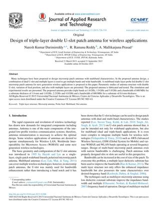
  • 6. N.K. Darimireddy et al. / Journal of Applied Research and Technology 13 (2015) 526–534 531 1.00 2.50 –7.50 –10.00 –12.50 –15.00 –17.50 –20.00 –2.50 –5.00 0.00 2.00 3.00 4.00 5.00 6.00 Freq [GHz] XY Plot 1 dB(St(coax_pin_T1,coax_pin_T1)) 7.00 8.00 9.00 10.00 Patch_Antenna_ADKv1 Curve info dB(St(coax_pin_T1,coax_pin_T1)) Setup1: Sweep Fig. 9. Return Loss plot when the patch is shifted 2 mm downwards. 1.00 2.00 3.00 4.00 5.00 6.00 Freq [GHz] XY Plot 4 7.00 8.00 9.00 10.00 –2.50 –7.50 –10.00 –12.50 –15.00 –17.50 –5.00 0.00 dB(St(coax_pin_T1,coax_pin_T1)) Patch_Antenna_ADKv1 Curve info dB(St(coax_pin_T1,coax_pin_T1)) Setup1: Sweep Fig. 10. Simulated Return Loss for 0.6 mm substrate thickness. 4.4. Simulated results of variable substrate thickness Varying the thickness of the substrate for top and bottom layers, the dual-band and sufficient impedance bandwidth characteristics are obtained. The optimum thickness of the substrate is 0.6 mm. But practically, fabrication of antenna with such less thickness is complex, so the thickness of 1.6 mm is considered. Figs. 10 and 11 show the Return Loss of antenna with thickness of 0.6 mm and 1.6 mm respectively. • Return Loss From Fig. 10 the Return Loss is −17.41 dB at 1.8 GHz, −17.42 dB at 2.2 GHz and −12.1 dB at 4.8 GHz. The impedance 1.00 –7.50 Name m1 m2 m3 X 1.6000 1.9000 3.8000 Y –10.7948 –15.9132 –20.1501 m1 m2 –12.50 –17.50 –22.50 2.00 3.00 4.00 5.00 6.00 Freq [GHz] XY Plot 1 dB(St(coax_pin_T1,coax_pin_T1)) 7.00 8.00 9.00 10.00 m3 Patch_Antenna_ADKv1 Curve info dB(St(coax_pin_T1,coax_pin_T1)) Setup1: Sweep Fig. 11. Simulated Return Loss for 1.6 mm substrate thickness.
  • 7. 532 N.K. Darimireddy et al. / Journal of Applied Research and Technology 13 (2015) 526–534 1.00 80.00 60.00 40.00 20.00 0.00 m1 m2 m3 2.00 3.00 4.00 5.00 6.00 Freq [GHz] XY Plot 2 7.00 8.00 9.00 10.00 Patch_Antenna_ADKv1 Curve info VSWRt(coax_pin_T1) Setup1: Sweep VSWRt(coax_pin_T1)Name m1 m2 m3 X 1.6000 1.9000 3.8000 Y 1.8113 1.3814 1.2180 Fig. 12. Simulated VSWR plot. Fig. 13. Fabricated structure of the patch. bandwidth obtained is 800 MHz with substrate thickness of 0.6 mm. From Fig. 11 it is observed that with substrate thick- ness of 1.6 mm the resonant frequencies of 1.6 GHz, 1.9 GHz and 3.8 GHz are obtained. • VSWR Fig. 12 shows that the VSWR values of the proposed antenna are 1.8113 at 1.6 GHz, 1.3814 at 1.9 GHz and 1.2180 at 3.8 GHz. Fig. 14. Fabricated structure of ground. Fig. 15. Side view of triple-layer fabricated antenna. From Figs. 10 and 11 it is observed that, with the variation of substrate thickness triple bands are obtained with improved bandwidth. It is difficult to provide the substrate with 0.6 mm thickness, so the design of antenna is carried out with substrate thickness of 1.6 mm. Fig. 12 shows that the VSWR is lesser than 2 at consequent resonant frequencies. 5. Fabricated structure and practical results The fabricated antenna with three layers is shown in Figs. 13–15 with patch and ground planes. Fig. 16 shows the experimental setup with Vector Network Analyzer (VNA). Fig. 16. Experimental setup of fabricated antenna.
  • 8. N.K. Darimireddy et al. / Journal of Applied Research and Technology 13 (2015) 526–534 533 Fig. 17. Return Loss of fabricated antenna. Fig. 18. VSWR graph of fabricated antenna. • Return Loss Fig. 17 shows the Return Loss curve of fabricated antenna displayed on VNA. The obtained simulated resonant frequen- cies are 1.6 GHz, 1.9 GHz and 3.8 GHz. The tested results of fabricated antenna with Vector Network Analyzer (VNA) are nearly same as the simulated results and they are 1.54 GHz, 1.89 GHz and 3.81 GHz. The obtained impedance bandwidth of fabricated antenna is 600 MHz from 3.6 GHz to 4.2 GHz at center frequency 3.8 GHz.
  • 9. 534 N.K. Darimireddy et al. / Journal of Applied Research and Technology 13 (2015) 526–534 • VSWR Fig. 18 shows that the VSWR values at 1.54 GHz, 1.9 GHz and 3.78 GHz are 1.906, 1.722 and 1.909 respectively. 6. Conclusions The design of multilayer microstrip patch antenna has been proposed in this paper. The proposed triple-layer structure of the antenna can be used for multiple wireless applications. The inclusion of three layers in the antenna structure increases the bandwidth and it leads to the more coverage of frequencies. The proposed triple-layer double U-slot patch antenna is simulated in HFSS solver and fabricated using thermo-lithography pro- cess. It is observed from the extensive parametric study that the antennapossessestriplebandsinmostofthecases.Theproposed antenna has triple bands at 1.6 GHz, 1.9 GHz and 3.8 GHz and a bandwidth of 600 MHz. The experimental results are in close agreement with the simulated results. Conflict of interest The authors have no conflicts of interest to declare. References Balanis, C. A. (2005). Antenna theory analysis and design (3rd ed.). Wiley Publication. Ghassemi, N., Neshati, M. H., Rashed-Mohassel, J. (2007). Investigation of multi layer probe-fed microstrip antenna for ultra wideband operation. In Proceedings of Asia-Pacific microwave conference IEEE. Hoorfar, A. (1992). Accurate modeling of multi-layer microstrip antennas. In Proceedings of Asia-Pacific microwave conference Adelaide, IEEE, (pp. 207–210). Huynh, T., Lee, K.-F. (1995). Single-layer single-patch wideband microstrip antenna. Electronics Letters, 1310–1312. Kraus, J. D. (1988). Antennas (2nd ed.). New York, NY: McGraw-Hill. Kushwah, R. P. S., Dubey, M., Singhal, P. K. (2006). Design of a triple layer microstrip patch antenna. In 2006 IEEE international workshop on antenna technology, IWAT 2006 – Small antennas and novel metamaterials, 2006 (pp. 49–52). Lee, C. S., Nalbandian, V. (1993). Impedance matching of a dual-frequency microstrip antenna with an air gap. IEEE Transactions on Antennas and Propagation, 41(5), 680–682. Lee, K. F., Luk, K. M., Mak, K. M., Yang, S. L. S. (2011). On the use of U- slots in the design of dual- and triple-band patch antennas. IEEE Antennas and Propagation Magazine, 53(3), 60–74. Lee, K. F., Steven Yang, S. L., Kishk, A. A., Luk, K. M. (2010). The versatile U-slot patch antenna. IEEE Antennas and Propagation Magazine, 52(1), 71–88. Raju, G. S. N. (2005). Antennas and wave propagation. New Delhi: Pearson Education (Singapore) Pvt. Ltd. Ramesh, G., Prakash, B., Inder, B., Apisak, I. (2001). Microstrip antenna design handbook. Boston, London: Artech House Publications. Rao, N., Kumar, V. D. (2011). Gain and bandwidth enhancement of a microstrip antenna using partial substrate removal in multiple-layer dielec- tricsubstrate.InProgresselectromagneticsresearchsymposiumproceedings Suzhou, China, (pp. 1285–1289). Singh, V. K., Ali, Z., Singh, A. K., Ayub, S. (2013). Dual band microstrip antenna for UMTS/WLAN/WIMAX applications. In 2013 international conference on communication systems and network technologies (CSNT). IEEE (pp. 47–50). Vedaprabhu, B., Vinoy, K. J. (2010). An integrated wideband multifunctional antenna using a micro strip patch with two U-slots. Progress in Electromag- netics Research B, 22, 221–235. Wong, K. L. (2002). Compact and broadband microstrip antennas. Wiley Pub- lication.