Ch 25 measurement of lines & surfaces
•Download as PPTX, PDF•
6 likes•2,682 views

production

Recommended
More Related Content
What's hot
What's hot (20)
Similar to Ch 25 measurement of lines & surfaces
Similar to Ch 25 measurement of lines & surfaces (20)
More from Nandan Choudhary
More from Nandan Choudhary (20)
Recently uploaded
Recently uploaded (20)
Ch 25 measurement of lines & surfaces
- 1. Measurement of Lines & Surfaces By S K Mondal
- 2. Linear measurements Some of the instruments used for the linear measurements are: Rules (Scale) Vernier Micrometer (Most widely used, Working Standard) Height gauge Bore gauge Dial indicator Slip gauges or gauge blocks (Most accurate, End Standard)
- 3. Vernier Caliper A vernier scale is an auxiliary scale that slides along the main scale. The vernier scale is that a certain number n of divisions on the vernier scale is equal in length to a different number (usually one less) of main-scale divisions. nV = (n −1)S where n = number of divisions on the vernier scale V = The length of one division on the vernier scale and S = Length of the smallest main-scale division Least count is applied to the smallest value that can be read directly by use of a vernier scale. Least count = S − V = 1 S n
- 6. Metric Micrometer A micrometer allows a measurement of the size of a body. It is one of the most accurate mechanical devices in common use. It consists a main scale and a thimble Method of Measurement Step-I: Find the whole number of mm in the barrel Step-I: Find the reading of barrel and multiply by 0.01 Step-III: Add the value in Step-I and Step-II
- 7. Micrometer
- 8. ISRO-2009, 2011 In a simple micrometer with screw pitch 0.5 mm and divisions on thimble 50, the reading corresponding to 5 divisions on barrel and 12 divisions on thimble is (a) 2.620 mm (b) 2.512 mm (c) 2.120 mm (d) 5.012 mm
- 9. Bore Gauge: used for measuring bores of different sizes ranging from small-to-large sizes. Provided with various extension arms that can be added for different sizes.
- 10. Dial indicator: Converts a linear displacement into a radial movement to measure over a small range of movement for the plunger. The typical least count that can be obtained with suitable gearing dial indicators is 0.01 mm to 0.001 mm. It is possible to use the dial indicator as a comparator by mounting it on a stand at any suitable height. Principle of a dial indicator
- 11. Applications of dial indicator include: centering workpices to machine tool spindles offsetting lathe tail stocks aligning a vice on a milling machine checking dimensions
- 12. GATE – 2008 S-1 A displacement sensor (a dial indicator) measures the lateral displacement of a mandrel mounted on the taper hole inside a drill spindle. The mandrel axis is an extension of the drill spindle taper hole axis and the protruding portion of the mandrel surface is perfectly cylindrical. Measurements are taken with the sensor placed at two positions P and Q as shown in the figure. The readings are recorded as Rx = maximum deflection minus minimum deflection, corresponding to sensor position at X, over one rotation.
- 13. GATE – 2008 contd… from S-2 If Rp= RQ>0, which one of the following would be consistent with the observation? (A) The drill spindle rotational axis is coincident with the drill spindle taper hole axis (B) The drill spindle rotational axis intersects the drill spindle taper hole axis at point P (C) The drill spindle rotational axis is parallel to the drill spindle taper hole axis (D) The drill spindle rotational axis intersects the drill spindle taper hole axis at point Q
- 14. Slip Gauges or Gauge blocks These are small blocks of alloy steel. Used in the manufacturing shops as length standards. Not to be used for regular and continuous measurement. Rectangular blocks with thickness representing the dimension of the block. The cross-section of the block is usually 32 mm x 9 mm. Are hardened and finished to size. The measuring surfaces of the gauge blocks are finished to a very high degree of finish, flatness and accuracy.
- 15. Come in sets with different number of pieces in a given set to suit the requirements of measurements. A typical set consisting of 88 pieces for metric units is shown in. To build any given dimension, it is necessary to identify a set of blocks, which are to be put together. Number of blocks used should always be the smallest. Generally the top and bottom Slip Gauges in the pile are 2 mm wear gauges. This is so that they will be the only ones that will wear down, and it is much cheaper to replace two gauges than a whole set.
- 16. To make up a Slip Gauge pile to 41.125 mm A Slip Gauge pile is set up with the use of simple maths. Decide what height you want to set up, in this case 41.125mm. Take away the thickness of the two wear gauges, and then use the gauges in the set to remove each place of decimal in turn, starting with the lowest.
- 17. 41.125 -4.000 ______ 37.125 -1.005 _______ 36.120 -1.020 _______ 35.100 -1.100 _______ 34.000 -4.000 _______ 30.000 -30.000 _______ 0.000 To make up a Slip Gauge pile to 41.125 mm
- 19. A Metric slip gauge set (88 Pieces) Slip gauges size or range, mm Increment, mm Number of Pieces 1.005 1.001 to 1.009 1.010 to 1.490 0.500 to 9.500 10 to 100 - 0.001 0.010 0.500 10.000 1 9 49 19 10
- 20. Comparators Comparator is another form of linear measuring method, which is quick and more convenient for checking large number of identical dimensions. During the measurement, a comparator is able to give the deviation of the dimension from the set dimension. Cannot measure absolute dimension but can only compare two dimensions. Highly reliable. To magnify the deviation, a number of principles are used such as mechanical, optical, pneumatic and electrical.
- 21. Fig. Principle of a comparator
- 22. GATE – 2007 (PI) Which one of the following instruments is a comparator ? (a) Tool Maker’s Microscope (b) GO/NO GO gauge (c) Optical Interferometer (d) Dial Gauge
- 23. Mechanical Comparators The Mikrokator principle greatly magnifies any deviation in size so that even small deviations produce large deflections of the pointer over the scale.
- 24. Sigma Mechanical Comparator The Sigma Mechanical Comparator uses a partially wrapped band wrapped about a driving drum to turn a pointer needle. The assembly provides a frictionless movement with a resistant pressure provided by the springs.
- 26. Mechanical Comparators The Eden-Rolt Reed system uses a pointer attached to the end of two reeds. One reed is pushed by a plunger, while the other is fixed. As one reed moves relative to the other, the pointer that they are commonly attached to will deflect.
- 27. Optical Comparators These devices use a plunger to rotate a mirror. A light beam is reflected off that mirror, and simply by the virtue of distance, the small rotation of the mirror can be converted to a significant translation with little friction.
- 28. Pneumatic Comparators Flow type: The float height is essentially proportional to the air that escapes from the gauge head Master gauges are used to find calibration points on the scales The input pressure is regulated to allow magnification adjustment
- 30. IFS-2015 Define a comparator. Write at least six desirable features it should possess. Also name four types of comparators. [ 8 Marks]
- 31. Angular Measurement This involves the measurement of angles of tapers and similar surfaces. The most common angular measuring tools are: Bevel protractor Sine bar
- 32. Bevel Protractor Is part of the machinist's combination square. The flat base of the protractor helps in setting it firmly on the workpiece and then by rotating the rule, it is possible to measure the angle. It will typically have a discrimination of one degree.
- 34. Sine Bar When a reference for a non-square angle is required, a sine bar can be used. Basically a sine bar is a bar of known length. When gauge blocks are placed under one end, the sine bar will tilt to a specific angle. Knowing the height differential of the two rollers in alignment with the workpiece ,the angle can be calculated using the sine formula. A sine bar is specified by the distance between the centre of the two rollers, i.e. 100 mm, 200 mm, & 300 mm. the various part of sine bar are hardened before grinding & lapping.
- 35. sin H L
- 36. GATE -2012 (PI) A sine bar has a length of 250 mm. Each roller has a diameter of 20 mm. During taper angle measurement of a component, the height from the surface plate to the centre of a roller is 100 mm. The calculated taper angle (in degrees) is (a) 21.1 (b) 22.8 (c) 23.6 (d) 68.9
- 37. Thread Measurements Threads are normally specified by the major diameter. Though there are a large variety of threads used in engineering, the most common thread encountered is the metric V-thread shown in Fig.
- 38. The parameters that are normally measured are: Major diameter Micrometer Pitch diameter Floating Carriage micrometer Wire method (Three wire and two wire) Pitch Screw pitch gauge Pitch measuring machine Thread form Optical projector
- 39. Three-Wire Method Three wires of equal diameter placed in thread, two on one side and one on other side Standard micrometer used to measure distance over wires (M) Different sizes and pitches of threads require different sizes of wires
- 41. The Three-Wire Method of Measuring Threads , pD pitchdiameter or Effectivediameter p pitchof thread and thread angle
- 42. Distance W over the outer edge Best wire size 1 cosec cot 2 2 2 For ISOmetricthread, 60 0.6496 3 1.5156 p p p W D d and D D p W D d p sec 2 2 For ISOmetricthread, 60 0.5774 p d d p
- 43. Two-Wire Method Two wires of equal diameter placed in thread, two on one side and one on other side
- 44. Pitch Diameter or Effective Dia. Best wire size cot cosec 1 2 2 2 Dimensionsunder thewire iameterof masterorstandardcylinder Micrometer readingoverstandardcylinder with two wire D Micrometer readingover theplugscrew gaugew p m s m s D T P p T d T D D D D D D ith thewire P= Pitch value sec 2 2 p d
- 45. GATE – 2011 (PI) The best wire size (in mm) for measuring effective diameter of a metric thread (included angle is 60o) of 20 mm diameter and 2.5 mm pitch using two wire method is (a) 1.443 (b) 0.723 (c) 2.886 (d) 2.086
- 46. GATE-2013 A metric thread of pitch 2 mm and thread angle 60 inspected for its pitch diameter using 3-wire method. The diameter of the best size wire in mm is (a) 0.866 (b) 1.000 (c) 1.154 (d) 2.000
- 47. GATE – 2011 (PI) To measure the effective diameter of an external metric thread (included angle is 60o) of 3.5 mm pitch, a cylindrical standard of 30.5 mm diameter and two wires of 2 mm diameter each are used. The micrometer readings over the standard and over the wires are 16.532 mm and 15.398 mm, respectively. The effective diameter (in mm) of the thread is (a) 33.366 (b) 30.397 (c) 29.366 (d) 26.397
- 49. Surfaces No surface is perfectly smooth, but the better the surface quality, the longer a product generally lasts, and the better is performs. Surface texture can be difficult to analyse quantitatively. Two surfaces may be entirely different, yet still provide the same CLA (Ra) value.
- 50. Surface geometry can be quantified a few different ways. Real surfaces are rarely so flat, or smooth, but most commonly a combination of the two.
- 51. Roughness height: is the parameter with which generally the surface finish is indicated. It is specified either as arithmetic average value or the root mean square value. Roughness width: is the distance parallel to the nominal part surface within which the peaks and valleys, which constitutes the predominant pattern of the roughness. Roughness width cut-off: is the maximum width of the surface that is included in the calculation of the roughness height.
- 54. Waviness: refers to those surface irregularities that have a greater spacing than that of roughness width. Determined by the height of the waviness and its width. The greater the width, the smoother is the surface and thus is more desirable. Lay direction: is the direction of the predominant surface pattern produced on the workpiece by the tool marks. Flaw: are surface irregularities that are present which are random and therefore will not be considered.
- 55. Diagram Symbol Description Parallel lay: Lay parallel to the Surface. Surface is produced by shaping, planning etc. Perpendicular lay: Lay perpendicular to the Surface. Surface is produced by shaping and planning Crossed lay: Lay angular in both directions. Surface is produced by knurling, honing. Lay
- 56. Diagram Symbol Description Multidirectional lay: Lay multidirectional. Surface is produced by grinding, lapping, super finishing. Circular lay: Approximately circular relative to the center. Surface is produced by facing. Radial lay: Approximately radial relative to the center of the nominal surface. Lay Contd..
- 57. Representation of Surface Roughness
- 58. Roughness Roughness Grade Number Roughness Symbol 50 N12 - 25 N11 12.5 N10 6.3 N9 3.2 N8 1.6 N7 0.8 N6 0.4 N5 0.2 N4 0.1 N3 0.05 N2 0.025 N1 ( )aR m
- 59. IES - 1992 Which grade symbol represents surface rough of broaching? (a) N12 (b) N8 (c) N4 (d) N1
- 60. Waviness height - the distance from a peak to a valley Waviness width - the distance between peaks or valleys Roughness width cutoff - a value greater than the maximum roughness width that is the largest separation of surface irregularities included in the measurements. Typical values are (0.003”, 0.010”, 0.030”, 0.100”, 0.300”) Lay - the direction the roughness pattern should follow Stylus travel is perpendicular to the lay specified.
- 61. Evaluation of Surface Roughness 1. Centre line average (CLA) or arithmetic mean deviation denoted as Ra. 2. Root mean square value (Rg) : rms value 3. Maximum peak to valley roughness (hmax) 4. The average of the five highest peak and five deepst valleys in the sample. 5. The average or leveling depth of the profile.
- 62. Determination of Mean Line M-System: After plotting the characteristic of any surface a horizontal line is drawn by joining two points. This line is shifts up and down in such a way that 50% area is above the line and 50% area is below the line
- 63. Determination of Mean Line E-System: (Envelop System) A sphere of 25 mm diameter is rolled over the surface and the locus of its centre is being traced out called envelope. This envelope is shifted in downward direction till the area above the line is equal to the area below the line. This is called mean envelope and the system of datum is called E- system.
- 64. Arithmetical Average: Measured for a specified area and the figures are added together and the total is then divided by the number of measurements taken to obtain the mean or arithmetical average (AA). It is also sometimes called the centre line average or CLA value. This in equation form is given by 0 1 1 ( ) L a iR y x dx y L N
- 65. GATE-2016 (PI) The roughness profile of a surface is depicted below. The surface roughness parameter Ra (in μm) is _______
- 66. The other parameter that is used sometimes is the root mean square value of the deviation in place of the arithmetic average , This in expression form is Fig. Surface roughness parameters 21 RMS iR y N
- 67. ISRO-2011 CLA value and RMS values are used for measurement of (a) Metal hardness (b) Sharpness of tool edge (c) Surface dimensions (d) Surface roughness
- 68. IES - 2008
- 69. Methods of measuring Surface Roughness There are a number of useful techniques for measuring surface roughness: Observation and touch - the human finger is very perceptive to surface roughness stylus based equipment - very common Interferometry - uses light wave interference patterns (discussed later)
- 70. Observation Methods Human perception is highly relative. To give the human tester a reference for what they are touching, commercial sets of standards are available. Comparison should be made against matched identical processes. One method of note is the finger nail assessment of roughness and touch method.
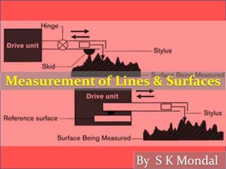
- 71. Stylus Equipment uses a stylus that tracks small changes in surface height, and a skid that follows large changes in surface height. The relative motion between the skid and the stylus is measured with a magnetic circuit and induction coils. One example of this is the Brown & Sharpe Surfcom unit.
- 74. Profilometer Measuring instrument used to measure a surface's profile, in order to quantify its roughness. Vertical resolution is usually in the nanometre level, though lateral resolution is usually poorer.
- 75. Contact profilometers A diamond stylus is moved vertically in contact with a sample and then moved laterally across the sample for a specified distance and specified contact force. A profilometer can measure small surface variations in vertical stylus displacement as a function of position. The radius of diamond stylus ranges from 20 nanometres to 25 μm.
- 76. Non-contact Profilometers An optical profilometer is a non-contact method for providing much of the same information as a stylus based profilometer. There are many different techniques which are currently being employed, such as laser triangulation (triangulation sensor), confocal microscopy and digital holography.
- 77. Advantages of optical Profilometers Because the non-contact profilometer does not touch the surface the scan speeds are dictated by the light reflected from the surface and the speed of the acquisition electronics. Optical profilometers do not touch the surface and therefore cannot be damaged by surface wear or careless operators.
- 78. Optical Flats Optical-grade clear fused quartz or glass structures lapped and polished to be extremely flat on one or both sides. Used with a monochromatic light to determine the flatness of other optical surfaces by interference. When a flat surface of another optic is placed on the optical flat, interference fringes are seen due to interference in the tiny gap between the two surfaces. The spacing between the fringes is smaller where the gap is changing more rapidly, indicating a departure from flatness in one of the two surfaces, in a similar way to the contour lines on a map.
- 82. When the fringes are perfectly straight and same fringe width for dark and bright band we conclude that the surface is perfectly flat. For convex surface the fringes curve around the point of contact. For concave surface the fringes curve away from the point of contact. th Thedistanceof air gapbetween twosuccessivefringesisgiven by 2 Distanceof air gapof interferencefringeof n orderis 2 n
- 83. GATE-2016 Two optically flat plates of glass are kept at a small angle θ as shown in the figure. Monochromatic light is incident vertically. If the wavelength of light used to get a fringe spacing of 1 mm is 450 nm, the wavelength of light (in nm) to get a fringe spacing of 1.5 mm is _______
- 84. For IES Only
- 85. Optical flat as a comparator
- 86. 2 n l h separation of edges n number of fringes / cm The difference of height between gauges wevlength of monochomaticlight Wherel h
- 87. GATE - 2003 Two slip gauges of 10 mm width measuring 1.000 mm and 1.002 mm are kept side by side in contact with each other lengthwise. An optical flat is kept resting on the slip gauges as shown in the figure. Monochromatic light of wavelength 0.0058928 mm is used in the inspection. The total number of straight fringes that can be observed on both slip gauges is (a) 2 (b) 6 (c) 8 (d) 13
- 88. GATE – 2011 (PI) Observation of a slip gauge on a flatness interferometer produced fringe counts numbering 10 and 14 for two readings. The second reading is taken by rotating the set-up by 180o. Assume that both faces of the slip gauge are flat and the wavelength of the radiation is 0.5086 µm. The parallelism error (in µm) between the two faces of the slip gauge is (a) 0.2543 (b) 1.172 (c) 0.5086 (d) 0.1272
- 89. Talysurf It is based upon measuring the generated noise due to dry friction of a metallic blade which travels over the surface under consideration. If the frictional force is made small enough to excite the blade, and not the entire system, then the noise will be proportional to surface roughness, and independent of the measured specimen size and material. The specimen surface roughness was measured by a widely used commercial instrument (Talysurf 10), and the prototype transducer.
- 91. @ Facebook Profile: Swapan Kumar Mondal www.facebook.com/SKMondalIES 09582314327 E-mail: swapan_mondal_01@yahoo.co.in
- 92. Ans. (d)