Downloaded 5,840 times
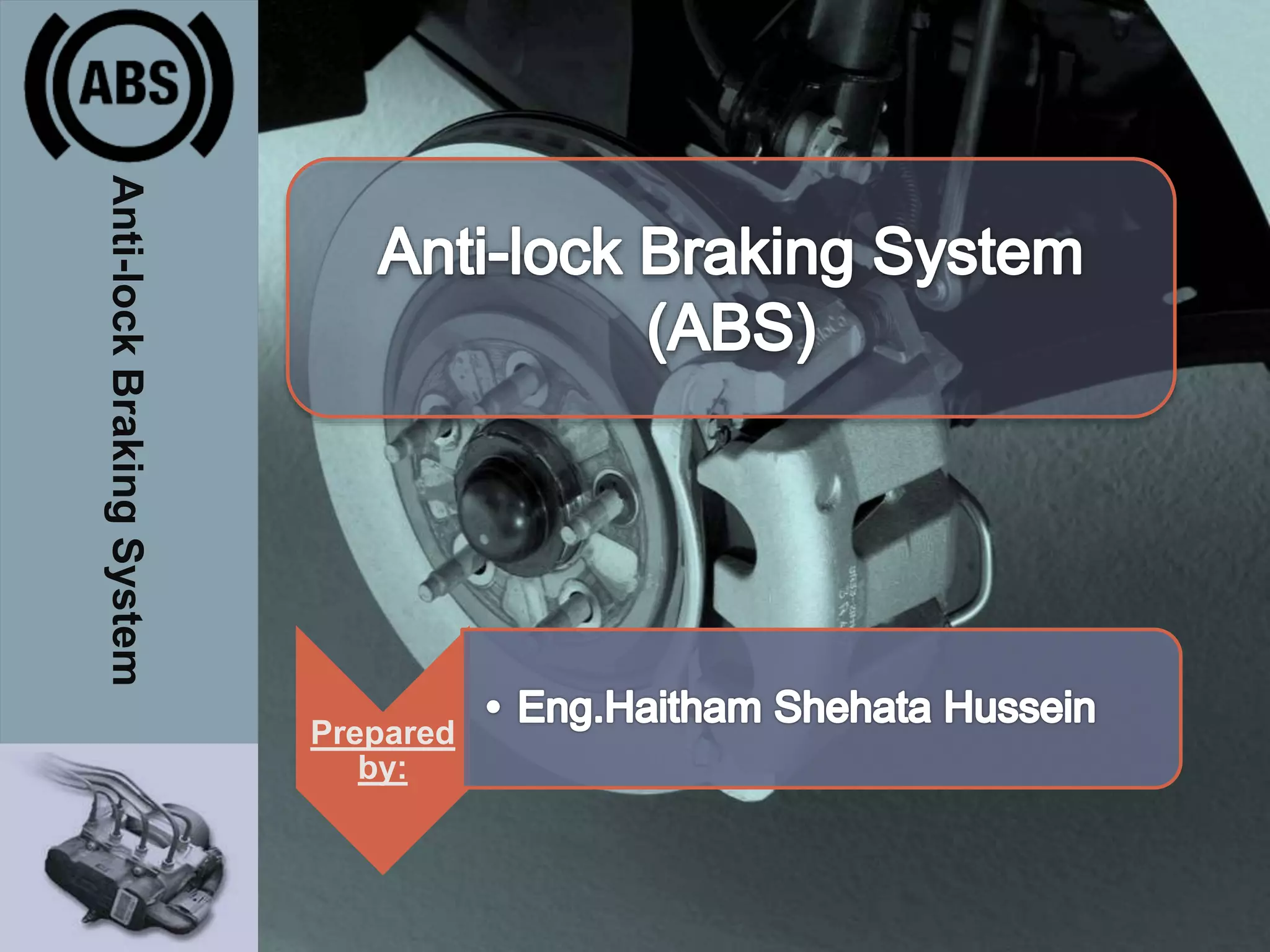

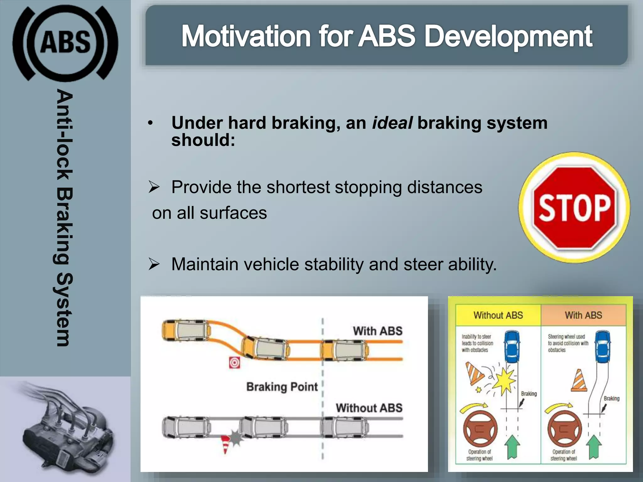


The document provides a comprehensive overview of the Anti-Lock Braking System (ABS), detailing its history, components, operation principles, and types of configurations. It explains how ABS prevents wheel locking during braking to maintain vehicle control and safety, while highlighting its advantages and disadvantages. Additionally, it addresses common concerns and problems associated with ABS, including maintenance challenges and sensor issues.


