11. Turnouts on Concrete Sleepers
Sleeper Orientation
Switch Portion-
Perpendicular to main line
Lead Portion-
Laid with their axis at an angle of /2 with the perpendicular to the main line
where, is the angle between the perpendicular to main line and the
perpendicular to the tangent drawn on gauge face of outer rail of turnout at
that point ( goes on increasing towards crossing)
Crossing Portion-
Sleepers axis perpendicular to bisector of crossing angle.
(spacing along the bisector of crossing angle)
22. 6
28
6
22
12R
Q
Bottom of Tongue Rail
Bottom of Stock Rail
Top of
Tongue Rail
Top of Stock
Rail
JOH
13
6 mm High
Tongue Rail
144
156.4 172
1682
5840
Head Width 13mm
Vertical Planning Of Tongue Rail
60 Kg UIC, 1 in 12 Turn Out
4244
166
Level Point
Head Width 43.3 mm
43.3
23. 1 in 12 Curved Switch (RDSO/T-4218, 60kg,PSC)
Pre-Curving of Tongue and Stock Rail
ATS
SRJ
ATS
26. Points and Crossings are laid without Cant
Approach rails are Canted (1 in 20)
Improper fishing at SRJ and Heel of Crossing
Reverse canting of sleepers in 4 sleepers
On all three sides
1AS, 2AS, 3A, and 4A (Before SRJ)
1E, 2E, 3E, and 4E (Beyond Heel of Crossing)
(on both Straight and Turnout side)
Running out Cant on Approaches
28. Running out level difference between
SR and TR behind Heel of switch
29. PROVISIONS IN IRPWM
• The tongue rail and stock rail shall be fabricated in workshop as
per standard RDSO drawings. Field officials should check the
curvature of Stock Rail and Tongue Rail before laying. In case
of Turn out taking off from curve suitable curvature as per
resultant lead radius to be provided both in Stock Rail and
Tongue Rail.
• The versine at each station in lead curve and turn in curve
should not be beyond 3 mm, from its design value, as a good
maintenance practice.
33. Check Rail Clearance
Tighter clearance causes wear on check rail & slackness
causes wheels to strike ANC & wear of nose of crossing.
34. • Check Rail Clearance c < G – g – tmax
For Gauge 1676 mm = 1676 - 1600 - 28.5
= 47.5 mm ( max.)
(Limits as per SOD 48 to 44 mm)
For Gauge 1673 mm = 1673 – 1600 – 28.5
= 44.5 mm
(Limits as per SOD 45 to 41 mm)
Check Rail clearance
35. Various factors limiting speeds over turnouts are as follows:
A-Kink in the turnout route at the toe of switch rail
B-Entry from straight to curve without transition – This is eliminated in curved switches
C- Lead curve without super-elevation
D-Entry from curve to straight without transition
E-Gap at the V of crossing
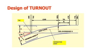
40. 2- Turnout with Curved
Switches
The lead curves in
these layouts starts
at toe of switch, are
tangential to the
switch angle and
meets the straight
leg of crossing at a
distance ‘w’ from
the TNC of the
crossing
iiikkkkkkkkkkkkkkkkkkkkk
kkkkkkkkkkkkkkkkkkkkkk
kkkkkkkkkkkkkkkkkkkkkk
kkkkkkkkkkkkkkkkkkkkkk
kkkkkkkkkkkkkkkkkkkkkk
kkkkkkkkkkkkkkkkkkkkkk
kkkkkkkkkkkkkkkkkkkkkk
kkkkkkkkkkkkkkkkkkkkkk
kkkkkkkkkkkkkkkkkkkkkk
kkkkkkk
41. At toe of switch, thickness of tongue rail is ‘t’. Derivation for
lead curve radius will be same as for straight switches. The same
can be derived by substituting ‘t’ (toe thickness) for ‘d’ (the heel
divergence).