1. Design of Combined Footing 2018
Miss. Shinde B.M. (Asst. Prof. Civil Engg. Dept. Sanjivaini College of Engineering, Kopargaon)
Design of Combined Footing
1. Introduction
Footings are structural members used to support columns and walls and to transmit and
distribute their loads to the soil in such a way that the load bearing capacity of the soil is
not exceeded, excessive settlement, differential settlement, or rotation are prevented
and adequate safety against overturning or sliding is maintained. The footing that
supports two or more columns is called as Combined Footing.
2. Need for Combined Footing
The combined footing is mainly provided in following circumstances,
a. When the foundation of the two columns is overlapped i.e. the distance between the
columns is very less.
b. When the safe bearing capacity of soil is too low.
c. When the exterior column is near about the property line.
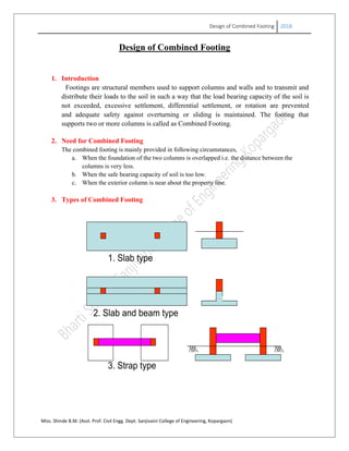
3. Types of Combined Footing
2. Slab and beam type
3. Strap type
1. Slab type
2. Design of Combined Footing 2018
Miss. Shinde B.M. (Asst. Prof. Civil Engg. Dept. Sanjivaini College of Engineering, Kopargaon)
The slab type of combined footing is provided into two shapes, rectangular and
trapezoidal as,
Rectangular Combined Footing Trapezoidal Combined Footing
4. Forces acting on Combined Footing
Longitudinally, the footing acts as an upward loaded beam spanning between
columns and cantilevering beyond.
Using statics, the shear force and bending moment diagrams in the longitudinal
direction are drawn.
The footing is also subjected to transverse bending
3. Design of Combined Footing 2018
Miss. Shinde B.M. (Asst. Prof. Civil Engg. Dept. Sanjivaini College of Engineering, Kopargaon)
In case of combined footing ,due to two point loading of columns it is get divided into three parts
along the longitudinal side, cantilever along the sides of columns A and B and middle portion
between column AB. The sagging bending moment is occurred in cantilever side which develops
tension along bottom face of footing and hogging bending moment is occurred along middle
portion of column A & B which develops tension along top face of footing. Hence with respect
to the tension developed the main reinforcement is provided in combined footing as shown in
above fig. as,
Cantilever side of column A & B – Bottom Face
In between of Column A & B – Top face.
Also along the transverse direction the transverse bending moment is occurred below the column
A & B hence the transverse reinforcement is provided below the columns at bottom face.
Design of Slab type Rectangular Combined Footing
Design Parameters and Steps:
1. Find out the area of footing (Af) and decide the dimensions of footing (Lf X Bf )
1.1*Totalworkingloadon column Aand B
SafeBearingCapacityof soil
fA
2. Find out the offset distances as shown in fig. by using that the center of load and the centre of
footing is coincide, so that the uniform upward pressure from soil over the entire area.
1 22
fL
x a l x a
3. Find the depth of footing
Draw the shear force and bending moment diagram and find the sagging and hogging bending
moment below column A & B and between Column AB respectively. Then for the maximum
bending moment find the depth.
4. Check the depth for two way shear.
4. Design of Combined Footing 2018
Miss. Shinde B.M. (Asst. Prof. Civil Engg. Dept. Sanjivaini College of Engineering, Kopargaon)
5. Find the area of reinforcement for sagging and hogging bending moment in longitudinal direction
and provide along tension face. Further apply the development length check as per IS 456-2000,
and curtail the reinforcement.
1
0 d
M
L L
V
6. Find the transverse reinforcement below the column A & B. The transverse action of the footing
is occurring on width of (b+2d) called bandwidth, where b-is the width of column and d- is the
depth of footing.
7. Check for one way shear and if it is unsafe provide the shear reinforcement as per IS 456-2000.
8. Draw the sections along the longitudinal and transverse direction and show the reinforcement
details.
Example 1
Design a reinforced concrete combined rectangular footing for two columns A & B
carrying working loads 450KN & 650KN respectively. Column A is 300mm x 300mm
and column B is 300mm x 400mm size. The center to center distance of column is 3.5m.
Safe bearing capacity of soil is 180KN/m2
Use M20 and Fe415 materials. Draw all
details of reinforcement.
Ans:
Given-
Data Column A Column B
Size 300mm x 300mm 300mm x 400mm
Working load 450KN 650KN
Ultimate load (w)
(F.S=1.5)
675KN 975KN
C/C distance (l) 3.5m
SBC 180KN/m2
Materials M20 and Fe415
Design constants Kumax=0.48, Rumax=2.76,
Ptmax=0.96%
1. Determination of dimensions of footing (Lf x Bf)-
2
1.1*Totalworkingloadon column Aand B
SafeBearingCapacityof soil
1.1* 450 650
180
6.72
f
f
f
A
A
A m
Assume Bf= 1.5m,
5. Design of Combined Footing 2018
Miss. Shinde B.M. (Asst. Prof. Civil Engg. Dept. Sanjivaini College of Engineering, Kopargaon)
6.72
4.48
1.5
fL m
Provide Combined Footing of size (lf x Bf)= (4.5m x 1.5m)
2. Find offset distances (a1, a2)
2
1 2
*
975*3.5
675 675
2.068
w l
x
w w
x
x m
using,
1 2
1 2
1 2
2
4.52.068 3.5 2.068
2
0.182 0.818
fL
x a l x a
a a
a m a m
3. Determination of upward soil pressure-
1 2
2 2
*
675 975
1.5*4.5
244.44KN/m 1.5* 270KN/m
244.44*1.5 366.67KN/m alonglength
244.44*4.5 1099.98KN/m along width
u
u
u
u
u
w w
q
Bf Lf
q
q SBC
q
q
4. Shear force and bending moment diagram-
6. Design of Combined Footing 2018
Miss. Shinde B.M. (Asst. Prof. Civil Engg. Dept. Sanjivaini College of Engineering, Kopargaon)
675kN 975kN
366.67 kN/m
0.182 m 0.818 m3.5 m
C
A B
D
E
ME=498.45 kN-m
MA=6.072 kN-m
+
_
.+
X=0.10 m 0.182m
MB=122.99 kN-mBMD at Ultimate
V1=66.73 kN
V4=299.92 kN
V2=608.26 kN
V3=675.08 kN
SFD at Ultimate
+
+
-
X1=1.84 m X2=2.66 m
E
-
5. Determination of depth of footing-
6
max
max*
498.45 10
2.76 1500
346.98
M
d
Ru Bf
X
d
X
d mm
Provide D= 500 mm
d = D-dc’= 500 – 50= 450 mm
Provide overall depth of Combined Footing (D)= 500mm
d = 450mm
7. Design of Combined Footing 2018
Miss. Shinde B.M. (Asst. Prof. Civil Engg. Dept. Sanjivaini College of Engineering, Kopargaon)
6. Check depth for two way shear-
For column B load is more, hence consider check for column B
Critical section for two way shear is taken at a distance of d/2 from face of
column B.
0
0
0 0
3
300 750
2 2
400 850
2 2
,
675 975
975 0.75 0.85
1.5 4.5
819.17
2 3200
,
819.17 10
3200 450
0.568
u
u
u
u
u
d d
L mm
d d
B mm
Punching Shear Force
V X
X
V KN
Perimeter L B mm
Punching Shear Stress
V X
PerimeterX d X
MPa
As per clause 31.6.3.1 page 58 & 59
0.5
0.3
0.5
0.4
1.25 1.0
1.0
0.25 0.25 20 1.118
* 1.118
c
c c
short sizeof column
Ks
long sizeof column
Ks
Ks
Ks
X fck X MPa
Ks PMPa
8. Design of Combined Footing 2018
Miss. Shinde B.M. (Asst. Prof. Civil Engg. Dept. Sanjivaini College of Engineering, Kopargaon)
, 0.568 1.118u ccomparing safe
7. Design of Longitudinal Reinforcement-
a. Ast Below Column A-
MA=6.072KN.m
min
min
min
2
6
2
2 2
( 26.5.2.1 .48)
4.60.5 0.12
1 1
100
0.5 20 4.6 6.072 10 0.12
1 1 450 1500 1500 500
415 20 1500 450 100
37.43 900
900
u
st st
st st
st st
st
clause Pg
X MX fck
A d X Bf A X Bf X D
fy fck X Bf Xd
X X X
A X A X X
X X
A mm A mm
A m
2
16
900
. 4.47 5
201
st
st
m
Assume mm
A
No of bars
a
check for development length-
Clause 26.2.3.3 page 44
1
0
1 0
0
1
47 47 16 752
12 450
int co t
608.26 366.67 0.1 571.59
571.59 752 450 172.62 .
. . .6.072 . 5
. .
d
d
d
M
L L
V
M V L L
L X mm
L d or whichever is greater mm
V Shear forceat po of n raflexure
V X KN
M KN m
No of bars for B M KN m
No of bars for B
.172.62 . 5M KN m
Provide 5 no. of 16mm dia. Bars cantilever side of column A and extend all bars upto
another edge of footing towards column B at bottom face.
9. Design of Combined Footing 2018
Miss. Shinde B.M. (Asst. Prof. Civil Engg. Dept. Sanjivaini College of Engineering, Kopargaon)
b. Ast Below Column B-
MA=122.99KN.m
min
min
min
2
6
2
2 2
( 26.5.2.1 .48)
4.60.5 0.12
1 1
100
0.5 20 4.6 122.99 10 0.12
1 1 450 1500 1500 500
415 20 1500 450 100
775.87 900
90
u
st st
st st
st st
st
clause Pg
X MX fck
A d X Bf A X Bf X D
fy fck X Bf Xd
X X X
A X A X X
X X
A mm A mm
A
2
0
16
900
. 4.47 5
201
st
st
mm
Assume mm
A
No of bars
a
check for development length-
Clause 26.2.3.3 page 44
1
0
1 0
0
1
47 47 16 752
12 450
int co t
675.08 366.67 0.182 608.35
608.35 752 450 183.72 .
. . .122.99 . 5
.
d
d
d
M
L L
V
M V L L
L X mm
L d or whichever is greater mm
V Shear forceat po of n raflexure
V X KN
M KN m
No of bars for B M KN m
No of bars fo
. .183.72 . 5r B M KN m
Provide 5 no. of 16mm dia. Bars cantilever side of column B and extend all bars upto
another edge of footing towards column A at bottom face.
10. Design of Combined Footing 2018
Miss. Shinde B.M. (Asst. Prof. Civil Engg. Dept. Sanjivaini College of Engineering, Kopargaon)
c. Ast Between Column A and Column B-
MA=498.45KN.m
min
min
min
2
6
2
2 2
( 26.5.2.1 .48)
4.60.5 0.12
1 1
100
0.5 20 4.6 498.45 10 0.12
1 1 450 1500 1500 500
415 20 1500 450 100
3435.29 900
3
u
st st
st st
st st
st
clause Pg
X MX fck
A d X Bf A X Bf X D
fy fck X Bf Xd
X X X
A X A X X
X X
A mm A mm
A
2
435.29
20
3435.29
. 10.9 11
314
st
st
mm
Assume mm
A
No of bars
a
check for development length-
Clause 26.2.3.3 page 44
1
0
1 0
0
1
47 47 16 752
12 450
int co t
608.26 366.67 0.1 571.59
571.59 752 450 172.62 .
. . .498.95 . 11
.
d
d
d
M
L L
V
M V L L
L X mm
L d or whichever is greater mm
V Shear forceat po of n raflexure
V X KN
M KN m
No of bars for B M KN m
No of bars for
172.62
. .172.62 . 11 3.8 4
498.95
B M KN m X
Provide11 no. of 20mm dia. Bars in between column A and B and extend 4 no. of bars upto
edge of footing on both sides of footing at top face.
9. Design of reinforcement along transverse direction-
The transverse reinforcement is provided below column A and column B for a length of
bandwidth.
11. Design of Combined Footing 2018
Miss. Shinde B.M. (Asst. Prof. Civil Engg. Dept. Sanjivaini College of Engineering, Kopargaon)
Bw = b+d+d or available distance whichever is less.
a. Below Column A
2
6
6
300 450 182 300 / 2 782 790
int ,
675
569.62
1.5 0.79
0.6 0.6 / 2 0.79
80.99 .
80.99 10
2.76 790
192.72 450
0.5 20 4.6 80.99 10
1 1
415
w
u
uA u
uA
st
B mm mm
Upward pressure ensity
q KN m
X
M q X X
M KN m
check for depthd
X
d
X
d mm mm Safe
X X X
A
min
min
2
2 2
2
0.12
450 790 790 500
20 790 450 100
514.16 426.6
514.41
12
514.41
. 4.55 5
113
st
st st
st
st
st
X A X X
X X
A mm A mm
A mm
Assume mm
A
No of bars
a
Provide 5 no. of 12mm dia. Bars below column A in a width of 790mm along the
transverse direction at bottom face.
b. Below Column A
12. Design of Combined Footing 2018
Miss. Shinde B.M. (Asst. Prof. Civil Engg. Dept. Sanjivaini College of Engineering, Kopargaon)
2
6
300 450 450 1200
int ,
975
541.67
1.5 1.2
0.55 0.55 / 2 1.2
98.31 .
98.31 10
2.76 1200
172.29 450
w
u
uA u
uA
B mm
Upward pressure ensity
q KN m
X
M q X X
M KN m
check for depthd
X
d
X
d mm mm Safe
min
min
6
2
2 2
2
0.5 20 4.6 98.31 10 0.12
1 1 450 1200 1200 500
415 20 1200 450 100
620.16 720
720
12
720
. 6.37 7
113
st st
st st
st
st
st
X X X
A X A X X
X X
A mm A mm
A mm
Assume mm
A
No of bars
a
Provide 7 no. of 12mm dia. Bars below column B in a width of 1200mm along the
transverse direction at bottom face.
10. Check for one way shear-
In case of check for one way shear the critical section is taken at a distance d or at point
of contraflexure whichever is less.
a. In between column A and B
Critical section is taken at a distance of 182mm from face of column B
13. Design of Combined Footing 2018
Miss. Shinde B.M. (Asst. Prof. Civil Engg. Dept. Sanjivaini College of Engineering, Kopargaon)
2
300
675.08 366.67 182
2
553.34
100 100 314
0.51%
1500 450
19, .73, 456 2000
0.483 /
0.483 1500 450
326.16 553.34
Pr inf
uD
uD
c
uc c
uc uD
V
V KN
Ast X
Pt
bd X
fromTable Pg IS
N mm
V bd X X
V KN V KN
ovide shear re orcement
A
3
10 ,2
40.4 .73
0.87* * *
0.75
227.18 0.75 450
0.87 415 157.1 450
337.5
227.18 10
112.52
v
uD uc
v
v
ssume mm legged vertical stirrups HYSD Steel
clause Pg
fy Asv d
S d
Vs
Vs V V KN X
X X X
S mm
X
S mm
Provide 2-legged 10mm dia. HYSD steel bar @ 110mm C/C in between col. A & B
b. In cantilever side of column A & B
Critical section is taken at a distance of 450mm from face of column B
2
300
300 366.67 450
2
80
100 100 201
0.148%
1500 450
19, .73, 456 2000
0.26 /
0.26 1500 450
182.25 80
Pr min inf
uD
uD
c
uc c
uc uD
V
V KN
Ast X
Pt
bd X
fromTable Pg IS
N mm
V bd X X
V KN V KN
ovide imum shear re orcement
Provide 2-legged 10mm dia. HYSD steel bar @ 250mm C/C in cantilever side
col. A & B
11. Summery-
14. Design of Combined Footing 2018
Miss. Shinde B.M. (Asst. Prof. Civil Engg. Dept. Sanjivaini College of Engineering, Kopargaon)
Description
Size of Footing 4.5M x 1.5M
Depth of footing D=500mm
d=450mm
Cantilever Col. A Between Col. A & B Cantilever Col. A
Long. R/F 5 no. of 16mm dia. 11 no. 20mm dia. 5 no. of 16mm dia.
Transverse R/F 5 no. of 12mm dia. ---- 7 no. of 12mm dia.
Shear R/F 2-legged 10mm dia.
HYSD steel bar @
250mm C/C
2-legged 10mm dia.
HYSD steel bar @
110mm C/C
2-legged 10mm dia.
HYSD steel bar @
250mm C/C
12. Reinforcement Details-
Design of Slab and Beam type Rectangular Combined Footing
Design Parameters and Steps:
1. Find out the area of footing (Af) and decide the dimensions of footing (Lf X Bf )
1.1*Totalworkingloadon column Aand B
SafeBearingCapacityof soil
fA
2. Find out the offset distances as shown in fig. by using that the center of load and the centre of
footing is coincide, so that the uniform upward pressure from soil over the entire area.
15. Design of Combined Footing 2018
Miss. Shinde B.M. (Asst. Prof. Civil Engg. Dept. Sanjivaini College of Engineering, Kopargaon)
1 22
fL
x a l x a
3. Design of Base Slab
Find net upward pressure,
21 2
/
*1.0 /
u
u u
w w
q KN m
Af
q q m KN m
2
2
offset distanceof col.Aor col.whicheverismore
Find Depth of Slab, d=
Check for one wayshear
Find Area of Main reinforcement and area of distribution steel
u
u
u
u
q l
M
l
M
R b
4. Design of Central Beam
Find net upward pressure,
21 2
/
* /
* /
u
u u
u u
w w
q KN m
Af
q q Bf KN m along length
q q Lf KN m along width
Draw the shear force and bending moment diagram and find the sagging and hogging bending
moment below column A & B and between Column AB respectively. Then for the maximum
bending moment find the depth.
5. Check the depth for two way shear.
6. Design the c/s of beam as ,
If Sagging B.M. > Hogging B.M. T section in cantilever of Col. A & B
□
Rectangular section in between col. A and B
If Hogging B.M. > Sagging B.M. □ Section in cantilever of Col. A & B
Inverted
T section in between col. A and B
Find the area of reinforcement for sagging and hogging bending moment in longitudinal direction
and provide along tension face. Further apply the development length check as per IS 456-2000,
and curtail the reinforcement.
1
0 d
M
L L
V
7. Check for one way shear and if it is unsafe provide the shear reinforcement as per IS 456-2000.
8. Draw the R/F in beam along the longitudinal direction and in cross section. Draw reinforcement
details of base slab.
Copy protected with Online-PDF-No-Copy.com