
Recommended
Recommended
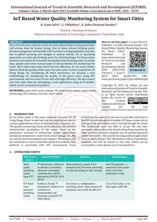
More Related Content
What's hot
What's hot (20)
Similar to IoT Based Water Quality Monitoring System for Smart Cities
Similar to IoT Based Water Quality Monitoring System for Smart Cities (20)
More from YogeshIJTSRD
More from YogeshIJTSRD (20)
Recently uploaded
Recently uploaded (20)
IoT Based Water Quality Monitoring System for Smart Cities
- 1. International Journal of Trend in Scientific Research and Development (IJTSRD) Volume 5 Issue 3, March-April 2021 Available Online: www.ijtsrd.com e-ISSN: 2456 – 6470 @ IJTSRD | Unique Paper ID – IJTSRD40058 | Volume – 5 | Issue – 3 | March-April 2021 Page 986 IoT Based Water Quality Monitoring System for Smart Cities A. Guna Selvi1, S. Vibhithra1, A. John Clement Sunder2 1Student, 2Assistant Professor, 1,2Bannari Amman Institute of Technology, Coimbatore, Tamil Nadu, India ABSTRACT Since from the last centuries, water has been affectedduetomanyparameters and actions done by human beings. Due to these actions drinking water becomes dangerous and harmful with increase in living population and also due to global warming and changes in natural climate. So, in upcoming generation we need safe drinking water for all living things. For these safety measures we need to first monitor the quality of the drinking water. In earlier days, people used some manual types of measurements for monitoring the water. But it takes more time and it has less efficiency. So, we need a better idea to check the quality of the water because water is more essential for all living things. By considering all these necessities, we develop a new methodology for monitoring the quality of the given water using IOT environment with low level of cost and with high efficiency. We also ensure real time data value by developing a web application using wi-fi module, which can be accessed at anywhere. KEYWORDS: water level, water leakage, Ph, temperature sensor, water quality monitoring, IOT, arduino, real time sensor values How to cite this paper: A. Guna Selvi | S. Vibhithra | A. John Clement Sunder "IoT Based Water Quality Monitoring System for Smart Cities" Published in International Journal of Trend in Scientific Research and Development(ijtsrd), ISSN: 2456-6470, Volume-5 | Issue-3, April 2021, pp.986-991, URL: www.ijtsrd.com/papers/ijtsrd40058.pdf Copyright © 2021 by author (s) and International Journal ofTrendinScientific Research and Development Journal. This is an Open Access article distributed under the terms of the Creative CommonsAttribution License (CC BY 4.0) (http://creativecommons.org/licenses/by/4.0) 1. INTRODUCTION As we know water is the major essential necessity for all living things. Water is used not only for drinking but also for various applications such as in industry field, irrigation, etc., The quality monitoring checks all the physical and chemical characteristic parameters of the water. Some of the parameters accessed in monitoring system applications include ph, temperature, water level, water leakage, etc., We use sensors for accessing these parameters. The sensors will be connected to a micro-controller which is an arduino. This platform is associated with IOT environment. From connecting the sensors to the micro-controller and then to the IOT device through wi-fimodule,IOTplaysamajorrolein linking all the parameters and in storing through the cloud. The authorized users are able to access the real time parameter values, that is the storedvaluesfromanywhereby login into their accounts using the user id and the password on the web server. This is done by using android application such as smart phones. The information will be transmitted, analyzed and will be stored in real time, which can be accessed by a smart phone user from anywhere. 2. LITERATURE SURVEY IJTSRD40058
- 2. International Journal of Trend in Scientific Research and Development (IJTSRD) @ www.ijtsrd.com eISSN: 2456-6470 @ IJTSRD | Unique Paper ID – IJTSRD40058 | Volume – 5 | Issue – 3 | March-April 2021 Page 987 3. NEED FOR THE WORK In the previous existing model, There is high cost of implementation and maintenance. No real time application No storage for sensor data Lacks accuracy and small coverage By considering all these limitations of previous existing model, our water quality monitoring system uses cloud storage technique for storing the data, so that it prevents loss of data and uses real time web application which can be accessed by the authorized users by login into their accounts which can be seen through smart phones from anywhere. 4. PROPOSED METHODOLOGY In this system, we are using arduino as the microcontroller. The whole system is designed in embedded-C and simulating the written code usingArduino IDE. For data collection on PH,waterlevel,temperatureandleakageofthesurroundingatmosphere, the water quality monitoring system employs sensors. These data’s can be accessed by authorized users by using a user ID and password on the web server by logging into their accounts. The gathered information is stored andanalyzedandtransmittedin real-time. A rectifier, relay and a transformer are connected with the microcontroller. The ESP8266 is a low cost wi-fi module consists of a full TCP/IP stack wi-fi chip and a microcontroller chip arduino, which facilitates the data storage in IOT cloud. The wi-fi module uses transmitter and receiver serial pins for sending and receiving data, for changing wireless module settings and for changing the serial query commands. The data from the sensors will be displayed on the LCD display. The code boots from external flash directly during the processing of the program, thereby increasing the system performance and storage requirements due to their optimized cache capacity. Finally, we can access the data on the web application using personal android phones. Fig 1 Block diagram of proposed system
- 3. International Journal of Trend in Scientific Research and Development (IJTSRD) @ www.ijtsrd.com eISSN: 2456-6470 @ IJTSRD | Unique Paper ID – IJTSRD40058 | Volume – 5 | Issue – 3 | March-April 2021 Page 988 5. CIRCUIT DESIGN Fig 2 Circuit diagram of proposed system 6. SYSTEM DESIGN A. ARDUINO (MICRO-CONTROLLER) Arduino Uno is known as Atmega328 whichisanAVR micro- controller. This has 2KB SRAM, flash memory of 32KB and 1KB of EEPROM. The arduino board has both digital and analog pins. It has 14 digital and 6 analog pins. For patterning these pins ON-chipADCisused.16Mhzfrequency crystal oscillator is used on the board. Figure 3 Arduino board There are many I/O digital and analog pins operating at 5V. These pins have ranging between 20mA to 40mA. Internal pull-up resistors are used, which limits the modern day exceeding from the given running conditions. However, too lots enlarge makes these resisters vain and will damagesthe device. Arduino Uno has built-in LED which is related through pin 13, which provide high price to the pin will make it ON and low will make it OFF. Vin, it is the entering voltage supplied to the Arduino Board. It is unique than 5V provided through a USB port. If a voltage is supplied via electricity jack, it can be accessed through this pin. 5V pin is used to furnish output regulated voltage. The board is powered up the usage of three approaches i.e., USB, Vin pin or DC energy jack. USB helps voltage round 5V and Vin and Power jack guide a voltage stage between 7V to 20V. It is operated at 5V. It is vital to notice that, if a voltage is furnished through 5V or 3.3V pins, they end result in by passing the voltage law that can injury the board if voltage surpasses from its limit. GND, these are floorpins.Morethan one floor pins are supplied on the board which can be used as per requirement. Reset, this pin is integratedonthe board which resets the application walkingontheboard.Insteadof bodily reset on the board, IDE comes with a characteristic of resetting the board through programming. IOREF, thispinis very beneficial for supplying voltage reference to the board. A protect is used to examine the voltage throughout this pin which then pick the applicable strength source. PWM is furnished through 3,5,6,9,10, 11pins. These pins are configured to provided 8-bit output PWM. Four pins 10(SS), 11(MOSI), 12(MISO), 13(SCK) grant SPI verbal exchange with the assist of SPI library. AREF, it is referred toasAnalog Reference. This pin is used for imparting a reference voltage to the analog inputs. TWI, it is known as Two-wire Interface. TWI verbal exchange is accessed through Wire Library. A4 and A5 pins are used for this purpose. Serial conversation is carried out between two pins known as Pin zero (Rx) and Pin 1 (Tx). Rx pin is used to acquire information whilst Tx pin is used to transmit data. Pin two and three are used for imparting exterior interrupts. An interrupt is known as by means of offering minimum or altering value. B. PH SENSOR PH is an electronic device which is used for measuring the pH level in water. It consists of threetypesofprobes(i)Glass electrode (ii) Reference electrode (iii) combination of gel electrode. pH is defined as the negative logarithm of hydrogen ion concentration in water. pH=-log[H+] A pH meter consists of special probes which are connected to an electronic meter that would display the reading. If the pH level is less than 7 then it is acidic in nature, if the pH level is greater than 7 then it is alkaline in nature, and generally the range of pH is 0-14pH. Operating range: 0-14. Operating temperature: 0-45. Operating voltage: -5 to 5 v. Output voltage: analog. Fig 4 PH sensor
- 4. International Journal of Trend in Scientific Research and Development (IJTSRD) @ www.ijtsrd.com eISSN: 2456-6470 @ IJTSRD | Unique Paper ID – IJTSRD40058 | Volume – 5 | Issue – 3 | March-April 2021 Page 989 C. TEMPERATURE SENSOR Temperature sensor is an integrated circuit sensor. The output voltage is linearly proportional to the centigrade temperature. The LM35 sensor is used in this project because the user cannot convert Kelvin to centigrade temperature. It is not suitable for remote applications and directly measures in Celsius. The applications of the temperature sensor are in microwave, fridges, household devices and air conditioners. It measures not only the heat but also measures cold temperature. They are two types of sensors; they are non-contact temperature sensor and contact temperature sensor. Contact temperature sensor is again divided into three types, they are electro mechanical, resistive resistance temperature detectors, and semiconductor based LM35, DS1820 etc. Fig 5 Temperature sensor D. WATER LEAKAGE SENSOR Water leakage sensor is designed for detectingwaterlevel in reservoir and overhead tanks. This is widely used in sensing the water leakage, water level and the rainfall. It consists of mainly three parts: 1MΩ resistor, an electronic brick connector and several lines of bare conducting wires. It works by having a series of exposed traces which are connected to ground. This is also interlaced between grounded traces and the sunstrokes. A weak pull up resistor of 1MΩ is present. 1MΩ resistor pulls up the sensor value until a drop of water shorts the sensor trace to the grounded trace. This can measure the water droplet/water size by using a series of exposed parallel wires. The characteristics are it has low power consumption and high sensitivity. Fig 6 Water leakage sensor E. Wi-Fi MODULE The WI-FI module used in this project is ESP8266. It follows TCP/IP stack and is a microchip which is less in cost. This microchip allows microcontroller to connect to a WI-FI network, by using Hayes style command connections are done or made throughTCP/IPconnection.ESP8266has1MB of built in flash, single chip devices able to connect WI-FI. Espressif systems are the manufacturers of this module, it is a 32-bit microcontroller. There are 16 GPIO pins in this module. This module follows RISC processor. It has 10-bit DAC. Later Espressif systems released a software development kit (SDK) which is used to programme on the chip, so that another microcontrollerisnotused.Someofthe SDK’s are Node MCU, Arduino, Micro Python, Zerynth and Mongoose OS. SPI, I2C, I2S, UART are used for communicating between two sensors or modules. Fig 7 Wi-Fi module F. LCD DISPLAY Liquid Crystal Display (LCD) screen is an electronic display module. An LCD has a wide range of applications in electronics. The most basic and commonly used LCD in circuits is the16x2 display. LCDs are commonly preferred in display because they are cheap, easy to programme and can display a wide range of characters and animations. A 16x2 LCD have two display lines each capable of displaying 16characters. This LCD has Command and Data registers. The command registers do command instructions given to the LCD while the Data register stores the data to bed is played by the LCD. Fig 8 LCD display 7. WORKING OF THE SYSTEM The system is based on IOT environment.Theset-upismade as per the circuit diagram. The power supply is given from the switch board and connected to the transformer which is a step-down transformer. The step-down transformer is used to convert 220volt power supply to 12-15volt supply. This is then connected to a bridge rectifier that is a full wave rectifier. This rectifier is used to convert AC current supply to DC supply. This is connectedtothemicro-controllerwhich is the arduino board. To know the water quality parameters such as PH, temperature, water level and leakage of the surrounding atmosphere we use sensors namely PH sensor, temperature sensor, water level and water leakage sensor. The PHsensor consists of measuring and reference electrode. These two electrodes when lifted in water shows some differences in their value. So, we will take some of the readings and took average for them. This will be done in the coding part. We can also measure moist, light and PH. In the outputsetup we have a black box connected to the PH which is the internal source to convert Ph meter to pulse wave. If the value is less than 7, it will be acidic in nature and more than 7 will be alkaline in nature. The temperature sensor used is LM35. This is used to show the value in degree Celsius. Othertemperaturesensorwill be measured in Fahrenheit and we have to convert it to degree Celsius. This will be a long process. So, we use LM35. It can measure approximately from -55 to 150 degree Celsius. The water leakage sensor detects when the voltage is low. That means when the voltage is low, there is some water leakage. The water float sensor is set to know the water level.Wewill set some saturated level, if the flow of water is above the saturated level, then there is high water flow. If the flow of water is below the saturated level, then there is low water
- 5. International Journal of Trend in Scientific Research and Development (IJTSRD) @ www.ijtsrd.com eISSN: 2456-6470 @ IJTSRD | Unique Paper ID – IJTSRD40058 | Volume – 5 | Issue – 3 | March-April 2021 Page 990 flow. From high current flow to low current flow, this will be controlled by using relay. If there is an open circuit, there will be no current flow. If any one of the sensor values is not detected or not in range, we will have a buzzer sound. The values from sensors are displayed on the LCD display. These values will be analysed, transmitted and stored in the cloud using the Wi-Fi module. The real time parameter values can be seen by the authorized users byloginintotheir accounts using the user id and password through the smart phone web application. 8. RESULT AND ANALYSIS A. HARDWARE OUTPUT Fig 9 Hardware output The hardware set up is made as per the above figure. When the current supply is given to the set-up, the step-down transformer reduces to 12-15V and the bridge rectifier will convert Ac to Dc supply. This is connected to the arduino micro-controller. The values from the sensors namely Ph, temperature, water level and water leakage sensors will be displayed on the LCD display which is connected to the micro-controller. The values are analysed, transmitted and stored in cloud using wi-fi module for real time applications. B. REAL TIME SENSOR VALUES Fig 10 Real time sensor values The real time sensor values from the web application is listed in the above figure. The values of four sensors which are Ph, temperature, water leakage and water level are calculated and displayed on the web screen. From these values, we can able to qualify and monitor the quality of the taken water. It displays with date and time so that we can able to know the real time values of each sensors. We already set some saturated value, if the value is above the saturation it displays high and if it is below the saturation it displays as low for water level values. The Ph defines the acidic or alkaline characteristics of the water. These values from the above figure has the significance in deciding the quality of water. This can be accessed from anywhere at any time using the web application. From this, we can conclude the safety in drinking water. 9. ADVANTAGES A. Real time application is made by using cloud storage technique, so that authorized users can use it from anywhere. B. More accuracy in data values. C. Cost implemented is less D. Interfacing of all the sensors in one system. 10. FUTURE SCOPE: In the upcoming generation, this proposed system by embedding artificial intelligence will be useful inmakingthe system autonomous with defining some sort of rules and regulations with high standards. This will bring use of automatic and smart distribution of waterwithouttheuseof human invention. The problem arising can be easily sorted out with automatic notification to the remote handling device to the accessed user. It can be used in industrial purposes. In industry, we can use ultrasonic sensorsin place of metallic wires which gives more accurate information. It may also be used in the flood prone regions and in dams for the people to be safe by knowing the water level quality and it can be informed by a notification. Therefore, if the level of water is above the saturated level, it will send notification upon the app so that we can alert the people. From this, many communication technologies can be introducedbased on our need of requirements. 11. CONCLUSION In this project, it explains about detail of the project and the use of the sensors and cloudstoragetechniqueandtoolsused for the smartcitieswaterqualitymonitoringsystemusingthe IOT platform. We used PH, temperature, water level and water leakage sensor for the measuring and knowing the quality of the present water. The datavaluesofthesensorare received and is displayed on the LCD screen display. The future techniquesand ideas can bedevelopedfromthisbasis. It is done in communication technologies and can be introduced as a software interface for further uses. So that it helps people to carry their own work at the same time and can view the real time data values fromany-whereandatany time using the smart mobile phones. It cost less and is small in size. It can be used at anywhere even in industrial level. It checks water level and quality of all different tanks with different liquids. We can alsouse this in higherlevel projects. The main advantage is that it provides adequate supply of water with good quality for safe drinking. By implementing this method of idea, there will be safe drinking of water in future and the quality of the water is monitored and checked where ever we are. 12. REFERENCES [1] An Internet of Things Based Model for Smart Water Distribution with Quality Monitoring, Joy Shah, P.G. Student, Department of Information Technology, Dharmsinh Desai University, Nadiad, Gujarat, India, International Journal of Innovative Research in Science, Engineering and Technology(An ISO 3297:
- 6. International Journal of Trend in Scientific Research and Development (IJTSRD) @ www.ijtsrd.com eISSN: 2456-6470 @ IJTSRD | Unique Paper ID – IJTSRD40058 | Volume – 5 | Issue – 3 | March-April 2021 Page 991 2007 Certified Organization) Website: www.ijirset.com, Vol. 6, Issue 3, March 2017. [2] Smart Water Management UsingIOT,SayaliWadekar, Vinayak Vakare, Ramratan Prajapati, Shivam Yadav, Vijaypal Yadav,978-1-5090-0893-3/16/$31.00,2016 IEEE. [3] 4th International Conference on Advances in Electrical, Electronics, Information, Communication and Bio-Informatics,Dr.Nageswara RaoMoparthi,Ch. Mukesh, Dr. P. Vidya Sagar, (AEEICB-18)978-1-5386- 4606-9, 2018 IEEE Water Quality Monitoring System Using IOT. [4] IoT based Water Parameter Monitoring System, Krishna S, Sarath TV, Proceedings of the Fifth International Conference on Communication and Electronics Systems (ICCES 2020) IEEE Conference Record # 48766; IEEE Xplore ISBN: 978-1-7281- 5371-1.