Pc controlled robot
•Download as DOCX, PDF•
0 likes•624 views

This document describes a PC controlled robot that uses a microcontroller, USB to TTL converter, motor driver IC, DC motor, and wheels. The PC sends commands to the microcontroller via USB and UART using X-CTU software. The microcontroller controls the motor driver IC which controls the DC motor direction and movement based on the received commands.

Recommended
More Related Content
What's hot
What's hot (19)
Viewers also liked
Viewers also liked (20)
Similar to Pc controlled robot
Similar to Pc controlled robot (20)
More from UVSofts Technologies
Recently uploaded
Recently uploaded (20)
Pc controlled robot
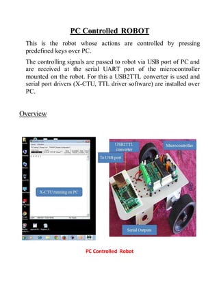
- 1. PC Controlled ROBOT This is the robot whose actions are controlled by pressing predefined keys over PC. The controlling signals are passed to robot via USB port of PC and are received at the serial UART port of the microcontroller mounted on the robot. For this a USB2TTL converter is used and serial port drivers (X-CTU, TTL driver software) are installed over PC. Overview PC Controlled Robot
- 2. Hardware components required and their purpose: 1. Microcontroller (ATMega8) development board 2. PC with a free USB port and X-CTU software 3. USB2TTL converter 4. DC motor 5. Motor driver IC (L293D) 6. Wheels 7. Power adopter Microcontroller (ATMega8) development board: This is the brain of this robot in which the program is loaded to do the required functioning and is interfaced with Bluetooth module and the motor driver to make the system work as required. PC with a free USB port and X-CTU software: This software is used to send the commands to robot using PC over its USB Port in ASCII format. These commands are defined in the program burnt into microcontroller. Commands are first operated by USB2TTL converter which then passes the commands in serial form over the microcontroller’s UART port. X-CTU Software
- 3. USB2TTL converter: This USB-to-Serial converter module converts USB signals (3.3 or 5V depending on the jumper setting) to serial TTL level signals (RX,TX, RTS, CTS, RI, DTR, DSR and DCD).The TTL signals are available on a single-row, 0.1" spaced, though-hole solder pads. The TX and RX signals can also be accessed via a mounted male header. Please note that this module converts the signals to TTL level and not to RS232 level. The intended usage of this module is to directly connect it to microcontroller’s Rx-Tx lines to interface it with the USB port of a PC. USB2TTL Converter DC Motor: This motor is controlled with DC voltages and can move in forward and backward direction according to the polarity of the voltage applied. Motor driver IC (L293D): Microcontrollers can’t supply the current required by DC motor to run. So, to fulfill this requirement these motor driver ICs are used.
- 4. DC motors with Driver IC Power adopter: This is used to give appropriate dc power supply to microcontroller, driver IC sensors and the other passive components of the robot. Wheels: In it three wheels are employed, two at rear end and one at front end. Rear wheels are attached with the motors and also control the steering of robot. Front wheel is the loose steered wheel which moves in the direction of the pressure applied to it.
- 5. Block Diagram: PC Controlled Robot Description For designing this robot, PC is first made to be equipped with required software (X-CTU, TTL driver, AVR compiler and burner). X-CTU sends commands in ASCII format which are received at UART port of microcontroller.
- 6. The commands are defined in the program burnt into microcontroller and on getting the specified command; the microcontroller sends the appropriate signals to the motor driver IC which in turn make the motor run in forward or backward direction or take a turn or to stop. Programming I/O port of ATMega8: Each port has three i/o registers associated with it which are designated as DDRx, PORTx, PINx. Port Registers in ATMega8
- 7. DDRx register: It stands for data direction register. This register is of 8 bits. Value of this register decides whether the port will act as input port or as output port. To make any port as input port, the contents of the associated DDRx register are made 0x00 and to make any port as output port, the contents of the associated DDRx register are made 0xff. PORTx register: This register is responsible for outputting any data to the port. Data to be outputted to any port is loaded to the corresponding PORTx register after making the direction of that port as output. For example: To send 0x14 to PORTA:- DDRA=0xFF; PORTA=0x14; PINx register: This register is responsible for inputting data from any port. Data to be inputted from any port is taken from the corresponding PINx register after making the direction of that port as input. For example: To get data from PORTB:- DDRA=0x00; var=PINB; //’var’ is a character type variable