More Related Content
Similar to Voltage to-frequency frequency-to-voltage converter (20)
Voltage to-frequency frequency-to-voltage converter
- 1. AN795
DS00795A-page 1© 2002 Microchip Technology, Inc.
Voltage-to-Frequency/Frequency-to-Voltage Converter
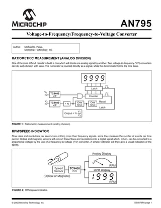
FIGURE 1: Ratiometric measurement (analog division).
Author: Michael O. Paiva,
Microchip Technology, Inc.
RATIOMETRIC MEASUREMENT (ANALOG DIVISION)
One of the most difficult circuits to build is one which will divide one analog signal by another. Two voltage-to-frequency (V/F) converters
can do such division with ease. The numerator is counted directly as a signal, while the denominator forms the time base.
Counter
Latch
V1
Output = N
Reset
TC9400
V/F
N
One
Shot
TC9400
V/F
Latch
÷
V2 One
Shot
V1
V2
TC9400
F/V
Speed
Sensor
(Optical or Magnetic)
Analog Display
DVM Display
RPM
RPM
RPM/SPEED INDICATOR
Flow rates and revolutions per second are nothing more than frequency signals, since they measure the number of events per time
period. Optical and magnetic sensors will convert these flows and revolutions into a digital signal which, in turn, can be converted to a
proportional voltage by the use of a frequency-to-voltage (F/V) converter. A simple voltmeter will then give a visual indication of the
speed.
FIGURE 2: RPM/speed indicator.
- 2. AN795
© 2002 Microchip Technology, Inc.DS00795A-page 2
MOTOR SPEED CONTROL
The motor's speed is measured with the F/V converter, which converts RPM into a proportional voltage. This voltage is used in a
negative feedback system to maintain the motor at the controlled setting.
Motor
+
–
Speed
Set
TC9400
F/V
Op
Amp
Pulse Type
Tachometer
(Optical or
Magnetic)
V+
FIGURE 3: Motor speed control.
PROPORTIONAL FLOW-RATE CONTROLLER
A TC9400 F/V converter can be used to regulate the amount of liquid or gas flowing through a pipeline. The flow-rate detector generates
a pulse train whose frequency is proportional to the rate of flow through it. The F/V converts this frequency to a proportional analog
voltage which is used to drive the valve controller. The valve controller regulates the valve so that the flow is steady, even though
pipeline pressure goes up and down. A voltmeter connected to the F/V converter output will indicate the actual instantaneous flow rate.
Flow Rate
Meter
Pulse Output
Flow
Set
Valve
Flow Rate
Detector
TC9400
F/V
Valve
Controller
FIGURE 4: Proportional flow-rate controller.
- 3. DS00795A-page 3© 2002 Microchip Technology, Inc.
AN795
TEMPERATURE METER
A temperature meter using the voltage output of a probe, such as one of the three shown, can be economically and straightforwardly
implemented with the TC9400 V/F converter. The V/F output is simply counted to display the temperature. For long-distance data
transmission, the TC9400 can be used to modulate an RF transmitter.
TC9400
V/F
Temperature Display
ResetLatchGate
Temp
Probe
50/60Hz
Gate
Latch
Reset
Temperature
Probes
A. Thermocouple B. Thermistor C. Transistor
Junction
One
Shot
One
Shot
Preamp
PreampPreamp Preamp
FIGURE 5: Temperature meter.
A/D CONVERSION WITH A MICROCONTROLLER
There are two schemes that can be utilized to accomplish A/D conversion with a microcontroller:
1. Depending on the number of digits of resolution required, VIN is measured by counting the FOUT frequency for 1ms, 10ms,
100ms, or 1 second. The final count is then directly proportional to VIN. (The microcontroller provides the time base.)
2. VIN is measured by determining the time between two pulses (negative edges). FOUT is used as a gate for counting the
microcontroller's clock. The final count will then be inversely proportional to VIN.
By taking the one's complement (changing 1's to 0's and 0's to 1's) of the final binary count, a value directly proportional to VIN will result.
This technique will give a faster conversion time when resolution is very important, but dynamic range is limited.
Digital
Output
VIN
TC9400
V/F
PIC
MicrocontrollerFOUT
FIGURE 6: A/D conversion with a microcontroller.
- 4. AN795
© 2002 Microchip Technology, Inc.DS00795A-page 4
13-BIT A/D CONVERTER
A 13-bit binary A/D converter can be built by combining the TC9400 V/F converter with a counter, latch, and time base. When the V/F
converter is set up for 10kHz full scale, a 1-second time base will provide one conversion per second.
4-DIGIT VOLTMETER WITH OPTOISOLATED INPUT
The use of a frequency counter will give a display of the V/F converter's frequency, which is directly proportional to the input voltage.
When the V/F converter is running at 10kHz full scale, a 1-second time base will give 4-digit resolution with 1 reading per second.
The optoisolator is used for transmitting the frequency, so there is no DC path to the frequency counter. This is especially useful in
medical applications, where a voltage probe should not be directly connected to the human body.
LONG-TERM INTEGRATOR WITH INFINITE HOLD
This system will integrate an input signal for minutes or days, and hold its output indefinitely. The data is held in a digital counter and
stays there until the counter is reset. Typical applications involve controlling the amount of surface metal deposited in a plating system
or how much charge a battery has taken on.
VIN
TC9400
V/F
Gate
Reset
Latch
Time
Base
13-bit Latch
13-bit Binary Counter
121110 9 8 7 6 5 4 3 2 1 0Bit
1MΩ
VIN
TC9400
V/F
Battery or
Transformer
Isolated
Supply Frequency Counter
+
V+
1MΩ
TC9400
V/F
Digital Display
VOUT
Reset
α
t
o∫
Binary
or BCD
Counter
D/A
Converter
VIN
VIN dtVOUT
FIGURE 7: 13-Bit A/D converter.
FIGURE 8: 4-Digit voltmeter with optoisolated input.
FIGURE 9: Long-term integrator with infinite hold.
- 5. DS00795A-page 5© 2002 Microchip Technology, Inc.
AN795
LONG-TERM INTEGRATOR FOR BIPOLAR (±) SIGNALS
When the input signal is negative as well as positive, there has to be a way of generating "negative" frequencies. An absolute value
circuit accomplishes this by giving the V/F converter a positive voltage only; and also telling the counter to count up for a positive
voltage and to count down for a negative voltage.
ANALOG SIGNAL TRANSMISSION OVER TELEPHONE LINES
The TC9400's square-wave output is ideal for transmitting analog data over telephone lines. A square wave is actually preferred over
a pulse waveform for data transmission, since the square wave takes up less frequency spectrum.
The square wave's spectrum can be further reduced by use of low-pass filters.
At the other end of the telephone line, the TC9400 converts the frequency signal back into a voltage output linearly proportional to the
original input voltage.
VIN
Reset
Up/Down
Counter
Up/Down
TC9400
V/F
+
–
+
–
Op
Amp
Absolute Value Circuit
Op
Amp
1MΩ
47kΩ
47kΩ 500kΩ
VIN
TC9400
F/V
9400
V/F
Telephone
System Linearity 0.03%~
Telephone VOUT
FIGURE 10: Long-term integrator for bipolar (±) signals.
FIGURE 11: Analog signal transmission over telephone lines.
- 6. AN795
© 2002 Microchip Technology, Inc.DS00795A-page 6
TELEMETRY
In a telemetry system, the TC9400 converts the analog input (VIN) into frequencies (10Hz to 100kHz) which can be used to modulate
an RF transmitter.
At the other end, a receiver picks up the RF signal and demodulates it back into the 10Hz to 100kHz spectrum. A frequency counter
connected to this signal then gives a count linearly proportional to the original analog voltage (VIN).
If a linearly-proportional analog output voltage is required, the counter can be replaced by a TC9400 used in the F/V mode.
HIGH NOISE IMMUNITY DATA TRANSMISSION
When transmitting analog data over long distances, it is advantageous to convert the analog signal into a digital signal, which is less
susceptible to noise pick-up.
In the system shown below, the TC9400 converts the input voltage into a pulse or square wave which is transmitted on a pair of wires
by use of a line driver and receiver. At the other end, the original voltage (VIN), can be digitally displayed on a frequency counter or
converted back to an analog voltage by use of a TC9400 F/V converter.
VIN
Digital Display
Gate Latch Reset
Time Base
CounterTC9400
V/F
RF
Transmitter
RF
Receiver
VIN
Analog Display
Digital Display
Gate Latch Reset
Time Base
Counter
Twisted
Pair Cable
Differential
Driver
Differential
Line
Receiver
TC9400
V/F
9400
F/V
FIGURE 12: Telemetry.
FIGURE 13: High noise immunity data transmission.
- 7. DS00795A-page 7© 2002 Microchip Technology, Inc.
AN795
FREQUENCY SHIFT KEYING (FSK) GENERATION AND DECODING
Frequency Shift Keying (FSK) is a simple means of transmitting digital data over a signal path (two wires, telephone lines, AM or FM
transmitters).
Typically, only two frequencies are transmitted. One corresponds to a logical "0," the other to a logical "1." A TC9400 V/F converter will
generate these two frequencies when connected as shown below. The potentiometer sets the V/F converter to the lower frequency.
The digital input then determines which frequency is selected. A "0" selects the lower frequency, a "1" selects the upper frequency.
The digital frequency signal is converted back into a digital format by a TC9400 used in the F/V mode.
ULTRALINEAR FREQUENCY MODULATOR
Since the TC9400 is a very linear V/F converter, an FM modulator is very easy to build.
The potentiometer determines the center frequency, while VIN determines the amount of modulation (FM deviation) around the center
frequency. VIN can be negative as well as positive.
Center
Frequency
VIN
V+
TC9400
V/F
Frequency Output
TC9400
F/V
Frequency
Offset
Center
Frequency
Digital
OutputInput
V+
0
1
0 0 0 0
1
TC9400
V/F
1
0 0 0 0
1
V+
FIGURE 16: Ultralinear frequency modulator.
FIGURE 15: Frequency Shift Keying (FSK) generation and decoding.
DC RESPONSE DATA RECORDING SYSTEM
Low-frequency analog data (DC to 10kHz) can be recorded anywhere, stored, and then reproduced. By varying the playback speed,
the frequency spectrum of the original data can be shifted up or down.
FIGURE 14: DC response data recording system.
V1
TC9400
V/F
TC9400
F/V
TC9400
F/V
TC9400
V/F
L
R
L
R
Cassette or
Reel-to-Reel
Recorder
V1
V2 V2
- 8. AN795
© 2002 Microchip Technology, Inc.DS00795A-page 8
FREQUENCY METER
The TC9400 will convert any frequency below 100kHz into an output voltage, which is linearly proportional to the input frequency. The
equivalent frequency is then displayed on an analog meter. If the incoming frequency is above 100kHz, a frequency divider in front of the
TC9400 can be used to scale the frequency down into the 100kHz region.
Analog Meter
FIN TC9400
F/V
VOUT
FIGURE 17: Frequency meter.
TACHOMETER BAR GRAPH DISPLAY
A tachometer can be constructed by using the TC9400 in the F/V mode to convert the frequency information (RPM) into a a linearly-
proportional voltage. This voltage is then compared to one of "n" comparators (8 in this example). When the voltage exceeds the trip
point of a comparator, the respective LED lights up and will continue to stay lit as long as the voltage exceeds the trip point. This gives
a bar-graph-type display, with the height of the bar being proportional to RPM.
FIGURE 18: Tachometer bar graph display.
Display
FIN
Visible
LEDs
Two TC1027
Quad Comparators
+
–
+
–
+
–
+
–
+
–
+
–
+
–
+
–
TC9400
F/V
V+
TC1027 VREF
- 9. DS00795A-page 9© 2002 Microchip Technology, Inc.
AN795
FREQUENCY/TONE DECODER
The frequency, or tone, to be detected is converted into a proportional analog voltage by the TC9400 F/V converter. The quad
comparators sense when the voltage (frequency) exceeds any of the four preset frequency limits. A logical "1" at any of the five
outputs indicates the frequency is within those limits.
This system is useful for determining which frequency band a signal is in, or for remote control, where each frequency band
corresponds to a different command.
FM DEMODULATION WITH A PHASE-LOCKED LOOP
The high linearity of the TC9400 (0.01%) is used to greatly improve the performance of a phase-locked loop, resulting in very precise
tracking of VOUT with respect to FIN.
FIGURE 19: Frequency/tone decoder.
FIGURE 20: FM demodulation with a phase-locked loop.
FIN
+
–
TC9400
F/V
+
–
+
–
+
–
Quad
Comparator
Frequency Set
VREF
V4 V3 V2 V1
FIN > F4 F4 < F
F3 < F < F4
F2 < F < F3
F1 < F < F2
0 < F < F1
FIN > F3
FIN > F2
FIN > F1
FIN
TC9400
V/F
VOUT
Frequency
Comparator
Loop
Filter
- 10. AN795
© 2002 Microchip Technology, Inc.DS00795A-page 10
ANALOG DATA TRANSMISSION ON DC SUPPLY LINES (TWO-WAY TRANSMITTER)
By converting an analog voltage to a linearly-proportional pulse train of short duration, it is possible to transmit this data on the same
wires used to energize the V/F converter.
The TC9400 V/F converter shorts out the DC supply for 3µsec out of each period. At 100kHz, the supply line is down 30% of the
10µsec period. As the frequency is lowered, the down-time decreases, so that at 1kHz the line is down only 0.3% of the time.
Two precautions are necessary to assure that the system does not stop functioning during the shorting period. At the power supply
end, a 1.2k resistor limits the current to 10mA on a 15V supply line. This prevents the TC9400 from being operated beyond its output
rating and at the same time prevents the supply from being shorted out. At the V/F end, a capacitor is used to keep the TC9400
energized, while the diode keeps the capacitor from being discharged.
Since the TC9400 requires only 2mA of current, a 1µF capacitor ensures a stable voltage (the ripple is only 6mV). Since the 3µsec
pulses appear at the left side of the 1.2kΩ resistor, it is easy to sense the signal here and convert the data back into a recognizable
format. A frequency counter connected at this point will directly display the input voltage by counting the frequency.
If an analog output is required, a TC9400 in the F/V mode can be used to convert the frequency back into a voltage. The overall
linearity is on the order of 0.03%, when both V/F and F/V are used. If only the V/F is used, 0.01% linearity can easily be achieved.
DIGITALLY CONTROLLED FREQUENCY SOURCE
This system generates frequencies controlled by a microcontroller counter, register, or thumb-wheel switches. Applications for such a
system include computer-controlled test equipment and numerically-controlled machine tools.
FIGURE 21: Analog data transmission on DC supply lines (two-way transmitter).
FIGURE 22: Digitally controlled frequency source.
Frequency
Counter
+
Remote Sensor
Analog Display
Analog
Input
TC9400
V/F
Digital Display
+
–
4 9
8
14
+
1µF
1.2kΩ 8-15V
DC
Power
Supply
3
–
TC9400
F/V
8
10
FOUT
1/2 FOUT
D/A TC9400
V/F
Digital
Signal
Source
- 11. DS00795A-page 11© 2002 Microchip Technology, Inc.
AN795
WIDE FREQUENCY RANGE PULSE GENERATOR
The TC9400 V/F converter is useful in the laboratory as a portable, battery-operated, low-cost frequency source. The TC9400
provides both pulse and square-wave outputs. By adding an op-amp integrator, a triangular waveform can also be generated. The
outputs can be frequency-modulated via the FM input.
FREQUENCY MULTIPLIER/DIVIDER WITH INFINITE RESOLUTION
Frequency scaling can easily be performed by first converting the incoming frequency into a proportional DC voltage. This is
accomplished by using the TC9400 in the F/V mode. Once the frequency is in a voltage format, it is easy to scale this voltage up or
down by use of a single potentiometer. The resultant voltage is then applied to a TC9400 V/F converter, which generates a
proportional output frequency.
Since the potentiometer is infinitely variable, the division/multiplication factor can be any number, including fractions (K1 is simply
VOUT/FIN, while K2 is FOUT/VIN).
FIGURE 23: Wide frequency range pulse generator.
FIGURE 24: Frequency multiplier/divider with infinite resolution.
V+
TC9400
V/F
FOUT
1/2 FOUT
FM
Input
Frequency
Adjust
Op
Amp
+
–
FIN
TC9400
V/F
TC9400
F/V
)
)
FOUT
VOUT
VIN
R2
R1
FOUT = K1 K2
R2
R1 + R2
FIN
- 12. AN795
© 2002 Microchip Technology, Inc.DS00795A-page 12
FREQUENCY DIFFERENCE MEASUREMENT
Frequency-difference measurement is accomplished by using two TC9400's in the F/V mode to convert both frequencies into two
proportional analog voltages (V1 and V2). V2 is inverted by a unity gain inverter. V1 and –V2 are then added by the summing op-amp
to give a voltage proportional to the frequency difference between F2 and F1.
Since the TC9400 V/F input is actually the summing junction to an op-amp, V1 and –V2 can be summed at the TC9400 input to
generate a frequency output proportional to the difference between F1 and F2.
CONVERTERS SIMPLIFY DESIGN OF FREQUENCY MULTIPLIER*
By using a programmable digital-to-analog converter in combination with frequency-to-voltage and voltage-to-frequency converters, this
circuit can multiply an input frequency by any number. Because it needs neither combinational logic nor a high-speed counter, it is more
flexible than competing designs, uses fewer parts, and is simpler to build.
As shown in the figure on the next page, the V/F converter, a TC9400, transforms the input frequency into a corresponding voltage. An
inexpensive device, the converter, requires only a few external components for setting its upper operating frequency as high as 100kHz.
Next the signal is applied to the reference port of the DAC-03 D/A converter, where it is amplified by the frequency-multiplying factor
programmed into the converter by thumbwheel switches or a microcontroller. The D/A converter's output is the product of the analog
input voltage and the digital gain factor.
R3 sets the gain of the op-amp to any value, providing trim adjustment or a convenient way to scale the D/A converter's output to a much
higher or lower voltage for the final stage, a TC9400 converter that operates in the voltage-to-frequency mode. The op-amp and R3 can
also be used to set circuit gain to non-integer values. The V/F device then converts the input voltage into a proportionally higher or lower
frequency.
FIGURE 25: Frequency difference measurement.
+
–
F2
TC9400
F/V
TC9400
F/V
TC9400
V/F
Op
Amp
–1
F1
V2
V1
–V2
FOUT = K1 (F1 – F2)
VOUT = K2 (F2 – F1)
- 13. DS00795A-page 13© 2002 Microchip Technology, Inc.
AN795
FIGURE 26: Circuit uses frequency-to-voltage-to-frequency conversion, with intermediate stage of gain between conversions, for
multiplyinginputfrequencybyanynumber.Digital-to-analogconverterisprogrammeddigitally,bythumbwheelswitchesormicrocontroller,
for coarse selection of frequency-multiplying factor; op-amp provides fine gain, enables choice of non-integer multiplication values.
*Reprinted with permission from Electronics, October 12, 1978; Copyright © Mc-Graw-Hill, Inc., 1978. All rights reserved.
TC9400
Frequency-
to-Voltage
Converter
Comp In
Offset
Gnd
Amp
Out
DAC-03
Digital-to-Analog
Converter
Offset
Gnd
Out
Amp Out
Comp In
Gnd
Analog
Gnd
V+
MSB
LSB
+
–
1
2
3
4
5
6
7
8
9
10 +5V
Digital
Gain Factor
(Programmable)
–5V
100kΩ
10kΩ
10
14
6
1
7
4
50kΩ
14
6
3
2
–15V
+15V
12
11
3
5
180pF
180pF
9
2
6
2
14
+5V
+5V
1
7
4
11
20kΩ
5
3
12
47pF
0.1
µF
1MΩ
15
1MΩ
100kΩ
TC9400
Frequency-
to-Voltage
Converter
17
18
16
12
11
13
+15V
–15V
MSB = Most Significant Bit
LSB = Least Significant Bit
100kΩ
2.2kΩ
REFOUT
IBIAS
VREF
VSS
VDD
fIN
IIN
RGAIN
10kΩ
VDD
OUTGND
IBIAS
REFOUT
IIN
VSS
VREF
510kΩ
fOUT
REFOUT
V–
REFIN VOUT Op
Amp
- 14. 2002 Microchip Technology Inc. DS00795A - page 14
Information contained in this publication regarding device
applications and the like is intended through suggestion only
and may be superseded by updates. It is your responsibility to
ensure that your application meets with your specifications.
No representation or warranty is given and no liability is
assumed by Microchip Technology Incorporated with respect
to the accuracy or use of such information, or infringement of
patents or other intellectual property rights arising from such
use or otherwise. Use of Microchip’s products as critical com-
ponents in life support systems is not authorized except with
express written approval by Microchip. No licenses are con-
veyed, implicitly or otherwise, under any intellectual property
rights.
Trademarks
The Microchip name and logo, the Microchip logo, FilterLab,
KEELOQ, microID, MPLAB, PIC, PICmicro, PICMASTER, PIC-
START, PRO MATE, SEEVAL and The Embedded Control Solu-
tions Company are registered trademarks of Microchip
Technology Incorporated in the U.S.A. and other countries.
dsPIC, ECONOMONITOR, FanSense, FlexROM, fuzzyLAB,
In-Circuit Serial Programming, ICSP, ICEPIC, microPort,
Migratable Memory, MPASM, MPLIB, MPLINK, MPSIM,
MXDEV, PICC, PICDEM, PICDEM.net, rfPIC, Select Mode
and Total Endurance are trademarks of Microchip Technology
Incorporated in the U.S.A.
Serialized Quick Turn Programming (SQTP) is a service mark
of Microchip Technology Incorporated in the U.S.A.
All other trademarks mentioned herein are property of their
respective companies.
© 2002, Microchip Technology Incorporated, Printed in the
U.S.A., All Rights Reserved.
Printed on recycled paper.
Microchip received QS-9000 quality system
certification for its worldwide headquarters,
design and wafer fabrication facilities in
Chandler and Tempe, Arizona in July 1999. The
Company’s quality system processes and
procedures are QS-9000 compliant for its
PICmicro®
8-bit MCUs, KEELOQ®
code hopping
devices, Serial EEPROMs and microperipheral
products. In addition, Microchip’s quality
system for the design and manufacture of
development systems is ISO 9001 certified.
- 15. DS00795A-page 15 2002 Microchip Technology Inc.
M
AMERICAS
Corporate Office
2355 West Chandler Blvd.
Chandler, AZ 85224-6199
Tel: 480-792-7200 Fax: 480-792-7277
Technical Support: 480-792-7627
Web Address: http://www.microchip.com
Rocky Mountain
2355 West Chandler Blvd.
Chandler, AZ 85224-6199
Tel: 480-792-7966 Fax: 480-792-7456
Atlanta
500 Sugar Mill Road, Suite 200B
Atlanta, GA 30350
Tel: 770-640-0034 Fax: 770-640-0307
Boston
2 Lan Drive, Suite 120
Westford, MA 01886
Tel: 978-692-3848 Fax: 978-692-3821
Chicago
333 Pierce Road, Suite 180
Itasca, IL 60143
Tel: 630-285-0071 Fax: 630-285-0075
Dallas
4570 Westgrove Drive, Suite 160
Addison, TX 75001
Tel: 972-818-7423 Fax: 972-818-2924
Detroit
Tri-Atria Office Building
32255 Northwestern Highway, Suite 190
Farmington Hills, MI 48334
Tel: 248-538-2250 Fax: 248-538-2260
Kokomo
2767 S. Albright Road
Kokomo, Indiana 46902
Tel: 765-864-8360 Fax: 765-864-8387
Los Angeles
18201 Von Karman, Suite 1090
Irvine, CA 92612
Tel: 949-263-1888 Fax: 949-263-1338
New York
150 Motor Parkway, Suite 202
Hauppauge, NY 11788
Tel: 631-273-5305 Fax: 631-273-5335
San Jose
Microchip Technology Inc.
2107 North First Street, Suite 590
San Jose, CA 95131
Tel: 408-436-7950 Fax: 408-436-7955
Toronto
6285 Northam Drive, Suite 108
Mississauga, Ontario L4V 1X5, Canada
Tel: 905-673-0699 Fax: 905-673-6509
ASIA/PACIFIC
Australia
Microchip Technology Australia Pty Ltd
Suite 22, 41 Rawson Street
Epping 2121, NSW
Australia
Tel: 61-2-9868-6733 Fax: 61-2-9868-6755
China - Beijing
Microchip Technology Consulting (Shanghai)
Co., Ltd., Beijing Liaison Office
Unit 915
Bei Hai Wan Tai Bldg.
No. 6 Chaoyangmen Beidajie
Beijing, 100027, No. China
Tel: 86-10-85282100 Fax: 86-10-85282104
China - Chengdu
Microchip Technology Consulting (Shanghai)
Co., Ltd., Chengdu Liaison Office
Rm. 2401, 24th Floor,
Ming Xing Financial Tower
No. 88 TIDU Street
Chengdu 610016, China
Tel: 86-28-6766200 Fax: 86-28-6766599
China - Fuzhou
Microchip Technology Consulting (Shanghai)
Co., Ltd., Fuzhou Liaison Office
Unit 28F, World Trade Plaza
No. 71 Wusi Road
Fuzhou 350001, China
Tel: 86-591-7503506 Fax: 86-591-7503521
China - Shanghai
Microchip Technology Consulting (Shanghai)
Co., Ltd.
Room 701, Bldg. B
Far East International Plaza
No. 317 Xian Xia Road
Shanghai, 200051
Tel: 86-21-6275-5700 Fax: 86-21-6275-5060
China - Shenzhen
Microchip Technology Consulting (Shanghai)
Co., Ltd., Shenzhen Liaison Office
Rm. 1315, 13/F, Shenzhen Kerry Centre,
Renminnan Lu
Shenzhen 518001, China
Tel: 86-755-2350361 Fax: 86-755-2366086
Hong Kong
Microchip Technology Hongkong Ltd.
Unit 901-6, Tower 2, Metroplaza
223 Hing Fong Road
Kwai Fong, N.T., Hong Kong
Tel: 852-2401-1200 Fax: 852-2401-3431
India
Microchip Technology Inc.
India Liaison Office
Divyasree Chambers
1 Floor, Wing A (A3/A4)
No. 11, O’Shaugnessey Road
Bangalore, 560 025, India
Tel: 91-80-2290061 Fax: 91-80-2290062
Japan
Microchip Technology Japan K.K.
Benex S-1 6F
3-18-20, Shinyokohama
Kohoku-Ku, Yokohama-shi
Kanagawa, 222-0033, Japan
Tel: 81-45-471- 6166 Fax: 81-45-471-6122
Korea
Microchip Technology Korea
168-1, Youngbo Bldg. 3 Floor
Samsung-Dong, Kangnam-Ku
Seoul, Korea 135-882
Tel: 82-2-554-7200 Fax: 82-2-558-5934
Singapore
Microchip Technology Singapore Pte Ltd.
200 Middle Road
#07-02 Prime Centre
Singapore, 188980
Tel: 65-6334-8870 Fax: 65-6334-8850
Taiwan
Microchip Technology Taiwan
11F-3, No. 207
Tung Hua North Road
Taipei, 105, Taiwan
Tel: 886-2-2717-7175 Fax: 886-2-2545-0139
EUROPE
Denmark
Microchip Technology Nordic ApS
Regus Business Centre
Lautrup hoj 1-3
Ballerup DK-2750 Denmark
Tel: 45 4420 9895 Fax: 45 4420 9910
France
Microchip Technology SARL
Parc d’Activite du Moulin de Massy
43 Rue du Saule Trapu
Batiment A - ler Etage
91300 Massy, France
Tel: 33-1-69-53-63-20 Fax: 33-1-69-30-90-79
Germany
Microchip Technology GmbH
Gustav-Heinemann Ring 125
D-81739 Munich, Germany
Tel: 49-89-627-144 0 Fax: 49-89-627-144-44
Italy
Microchip Technology SRL
Centro Direzionale Colleoni
Palazzo Taurus 1 V. Le Colleoni 1
20041 Agrate Brianza
Milan, Italy
Tel: 39-039-65791-1 Fax: 39-039-6899883
United Kingdom
Arizona Microchip Technology Ltd.
505 Eskdale Road
Winnersh Triangle
Wokingham
Berkshire, England RG41 5TU
Tel: 44 118 921 5869 Fax: 44-118 921-5820
03/01/02
*DS00795A*
WORLDWIDE SALES AND SERVICE