SlideShare a Scribd company logo
1 of 15
Download to read offline
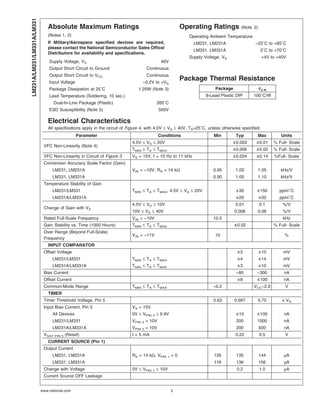
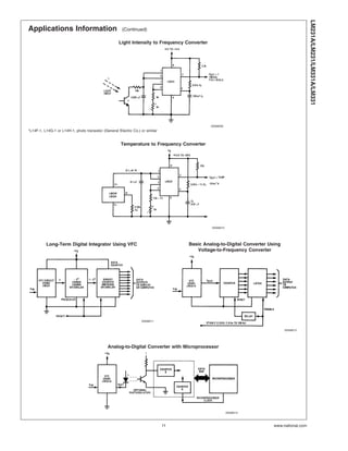
LM231A/LM231/LM331A/LM331
Precision Voltage-to-Frequency Converters
General Description
The LM231/LM331 family of voltage-to-frequency converters
are ideally suited for use in simple low-cost circuits for
analog-to-digital conversion, precision frequency-to-voltage
conversion, long-term integration, linear frequency modula-
tion or demodulation, and many other functions. The output
when used as a voltage-to-frequency converter is a pulse
train at a frequency precisely proportional to the applied
input voltage. Thus, it provides all the inherent advantages of
the voltage-to-frequency conversion techniques, and is easy
to apply in all standard voltage-to-frequency converter appli-
cations. Further, the LM231A/LM331A attain a new high
level of accuracy versus temperature which could only be
attained with expensive voltage-to-frequency modules. Ad-
ditionally the LM231/331 are ideally suited for use in digital
systems at low power supply voltages and can provide low-
cost analog-to-digital conversion in microprocessor-
controlled systems. And, the frequency from a battery pow-
ered voltage-to-frequency converter can be easily channeled
through a simple photo isolator to provide isolation against
high common mode levels.
The LM231/LM331 utilize a new temperature-compensated
band-gap reference circuit, to provide excellent accuracy
over the full operating temperature range, at power supplies
as low as 4.0V. The precision timer circuit has low bias
currents without degrading the quick response necessary for
100 kHz voltage-to-frequency conversion. And the output
are capable of driving 3 TTL loads, or a high voltage output
up to 40V, yet is short-circuit-proof against VCC.
Features
n Guaranteed linearity 0.01% max
n Improved performance in existing voltage-to-frequency
conversion applications
n Split or single supply operation
n Operates on single 5V supply
n Pulse output compatible with all logic forms
n Excellent temperature stability: ±50 ppm/˚C max
n Low power consumption: 15 mW typical at 5V
n Wide dynamic range, 100 dB min at 10 kHz full scale
frequency
n Wide range of full scale frequency: 1 Hz to 100 kHz
n Low cost
Connection Diagram
Dual-In-Line Package
00568021
Order Number LM231AN, LM231N, LM331AN,
or LM331N
See NS Package Number N08E
Ordering Information
Device Temperature Range Package
LM231N −25˚C ≤ TA ≤ +85˚C N08E (DIP)
LM231AN −25˚C ≤ TA ≤ +85˚C N08E (DIP)
LM331N 0˚C ≤ TA ≤ +70˚C N08E (DIP)
LM331AN 0˚C ≤ TA ≤ +70˚C N08E (DIP)
Teflon® is a registered trademark of DuPont
April 2006
LM231A/LM231/LM331A/LM331PrecisionVoltage-to-FrequencyConverters
© 2006 National Semiconductor Corporation DS005680 www.national.com
Absolute Maximum Ratings
(Notes 1, 2)
If Military/Aerospace specified devices are required,
please contact the National Semiconductor Sales Office/
Distributors for availability and specifications.
Supply Voltage, VS 40V
Output Short Circuit to Ground Continuous
Output Short Circuit to VCC Continuous
Input Voltage −0.2V to +VS
Package Dissipation at 25˚C 1.25W (Note 3)
Lead Temperature (Soldering, 10 sec.)
Dual-In-Line Package (Plastic) 260˚C
ESD Susceptibility (Note 5) 500V
Operating Ratings (Note 2)
Operating Ambient Temperature
LM231, LM231A −25˚C to +85˚C
LM331, LM331A 0˚C to +70˚C
Supply Voltage, VS +4V to +40V
Package Thermal Resistance
Package θJ-A
8-Lead Plastic DIP 100˚C/W
Electrical Characteristics
All specifications apply in the circuit of Figure 4, with 4.0V ≤ VS ≤ 40V, TA=25˚C, unless otherwise specified.
Parameter Conditions Min Typ Max Units
VFC Non-Linearity (Note 4)
4.5V ≤ VS ≤ 20V ±0.003 ±0.01 % Full- Scale
TMIN ≤ TA ≤ TMAX ±0.006 ±0.02 % Full- Scale
VFC Non-Linearity in Circuit of Figure 3 VS = 15V, f = 10 Hz to 11 kHz ±0.024 ±0.14 %Full- Scale
Conversion Accuracy Scale Factor (Gain)
LM231, LM231A VIN = −10V, RS = 14 kΩ 0.95 1.00 1.05 kHz/V
LM331, LM331A 0.90 1.00 1.10 kHz/V
Temperature Stability of Gain
LM231/LM331 TMIN ≤ TA ≤ TMAX, 4.5V ≤ VS ≤ 20V ±30 ±150 ppm/˚C
LM231A/LM331A ±20 ±50 ppm/˚C
Change of Gain with VS
4.5V ≤ VS ≤ 10V 0.01 0.1 %/V
10V ≤ VS ≤ 40V 0.006 0.06 %/V
Rated Full-Scale Frequency VIN = −10V 10.0 kHz
Gain Stability vs. Time (1000 Hours) TMIN ≤ TA ≤ TMAX ±0.02 % Full- Scale
Over Range (Beyond Full-Scale)
Frequency
VIN = −11V 10 %
INPUT COMPARATOR
Offset Voltage ±3 ±10 mV
LM231/LM331 TMIN ≤ TA ≤ TMAX ±4 ±14 mV
LM231A/LM331A TMIN ≤ TA ≤ TMAX ±3 ±10 mV
Bias Current −80 −300 nA
Offset Current ±8 ±100 nA
Common-Mode Range TMIN ≤ TA ≤ TMAX −0.2 VCC−2.0 V
TIMER
Timer Threshold Voltage, Pin 5 0.63 0.667 0.70 x VS
Input Bias Current, Pin 5 VS = 15V
All Devices 0V ≤ VPIN 5 ≤ 9.9V ±10 ±100 nA
LM231/LM331 VPIN 5 = 10V 200 1000 nA
LM231A/LM331A VPIN 5 = 10V 200 500 nA
VSAT PIN 5 (Reset) I = 5 mA 0.22 0.5 V
CURRENT SOURCE (Pin 1)
Output Current
LM231, LM231A RS = 14 kΩ, VPIN 1 = 0 126 135 144 µA
LM331, LM331A 116 136 156 µA
Change with Voltage 0V ≤ VPIN 1 ≤ 10V 0.2 1.0 µA
Current Source OFF Leakage
LM231A/LM231/LM331A/LM331
www.national.com 2
Electrical Characteristics (Continued)
All specifications apply in the circuit of Figure 4, with 4.0V ≤ VS ≤ 40V, TA=25˚C, unless otherwise specified.
Parameter Conditions Min Typ Max Units
CURRENT SOURCE (Pin 1)
LM231, LM231A, LM331, LM331A 0.02 10.0 nA
All Devices TA = TMAX 2.0 50.0 nA
Operating Range of Current (Typical) (10 to 500) µA
REFERENCE VOLTAGE (Pin 2)
LM231, LM231A 1.76 1.89 2.02 VDC
LM331, LM331A 1.70 1.89 2.08 VDC
Stability vs. Temperature ±60 ppm/˚C
Stability vs. Time, 1000 Hours ±0.1 %
LOGIC OUTPUT (Pin 3)
VSAT
I = 5 mA 0.15 0.50 V
I = 3.2 mA (2 TTL Loads),
TMIN ≤ TA ≤ TMAX
0.10 0.40 V
OFF Leakage ±0.05 1.0 µA
SUPPLY CURRENT
LM231, LM231A
VS = 5V 2.0 3.0 4.0 mA
VS = 40V 2.5 4.0 6.0 mA
LM331, LM331A
VS = 5V 1.5 3.0 6.0 mA
VS = 40V 2.0 4.0 8.0 mA
Note 1: Absolute Maximum Ratings indicate limits beyond which damage to the device may occur. DC and AC electrical specifications do not apply when operating
the device beyond its specified operating conditions.
Note 2: All voltages are measured with respect to GND = 0V, unless otherwise noted.
Note 3: The absolute maximum junction temperature (TJmax) for this device is 150˚C. The maximum allowable power dissipation is dictated by TJmax, the
junction-to-ambient thermal resistance (θJA), and the ambient temperature TA, and can be calculated using the formula PDmax = (TJmax - TA) / θJA. The values for
maximum power dissipation will be reached only when the device is operated in a severe fault condition (e.g., when input or output pins are driven beyond the power
supply voltages, or the power supply polarity is reversed). Obviously, such conditions should always be avoided.
Note 4: Nonlinearity is defined as the deviation of fOUT from VIN x (10 kHz/−10 VDC) when the circuit has been trimmed for zero error at 10 Hz and at 10 kHz, over
the frequency range 1 Hz to 11 kHz. For the timing capacitor, CT, use NPO ceramic, Teflon®, or polystyrene.
Note 5: Human body model, 100 pF discharged through a 1.5 kΩ resistor.
LM231A/LM231/LM331A/LM331
www.national.com3
Functional Block Diagram
00568002
Pin numbers apply to 8-pin packages only.
FIGURE 1.
LM231A/LM231/LM331A/LM331
www.national.com 4
Typical Performance Characteristics
(All electrical characteristics apply for the circuit of Figure 4, unless otherwise noted.)
Nonlinearity Error
as Precision V-to-F
Converter (Figure 4) Nonlinearity Error
00568025
00568026
Nonlinearity Error vs. Power
Supply Voltage Frequency vs. Temperature
00568027 00568028
VREF vs. Temperature
Output Frequency vs.
VSUPPLY
00568029 00568030
LM231A/LM231/LM331A/LM331
www.national.com5
Typical Performance Characteristics (Continued)
100 kHz Nonlinearity Error
(Figure 5)
Nonlinearity Error
(Figure 3)
00568031 00568032
Input Current (Pins 6,7) vs.
Temperature Power Drain vs. VSUPPLY
00568033 00568034
Output Saturation Voltage vs.
IOUT (Pin 3)
Nonlinearity Error, Precision
F-to-V Converter (Figure 7)
00568035 00568036
LM231A/LM231/LM331A/LM331
www.national.com 6
Applications Information
PRINCIPLES OF OPERATION
The LM231/331 are monolithic circuits designed for accu-
racy and versatile operation when applied as voltage-to-
frequency (V-to-F) converters or as frequency-to-voltage (F-
to-V) converters. A simplified block diagram of the LM231/
331 is shown in Figure 2 and consists of a switched current
source, input comparator, and 1-shot timer.
Simplified Voltage-to-Frequency Converter
The operation of these blocks is best understood by going
through the operating cycle of the basic V-to-F converter,
Figure 2, which consists of the simplified block diagram of
the LM231/331 and the various resistors and capacitors
connected to it.
The voltage comparator compares a positive input voltage,
V1, at pin 7 to the voltage, Vx, at pin 6. If V1 is greater, the
comparator will trigger the 1-shot timer. The output of the
timer will turn ON both the frequency output transistor and
the switched current source for a period t=1.1 RtCt. During
this period, the current i will flow out of the switched current
source and provide a fixed amount of charge, Q = i x t, into
the capacitor, CL. This will normally charge Vx up to a higher
level than V1. At the end of the timing period, the current i will
turn OFF, and the timer will reset itself.
Now there is no current flowing from pin 1, and the capacitor
CL will be gradually discharged by RL until Vx falls to the level
of V1. Then the comparator will trigger the timer and start
another cycle.
The current flowing into CL is exactly IAVE = i x (1.1xRtCt) x f,
and the current flowing out of CL is exactly Vx/RL . VIN/RL.
If VIN is doubled, the frequency will double to maintain this
balance. Even a simple V-to-F converter can provide a fre-
quency precisely proportional to its input voltage over a wide
range of frequencies.
Detail of Operation, Functional Block
Diagram (Figure 1)
The block diagram shows a band gap reference which pro-
vides a stable 1.9 VDC output. This 1.9 VDC is well regulated
over a VS range of 3.9V to 40V. It also has a flat, low
temperature coefficient, and typically changes less than 1⁄2%
over a 100˚C temperature change.
The current pump circuit forces the voltage at pin 2 to be at
1.9V, and causes a current i=1.90V/RS to flow. For Rs=14k,
i=135 µA. The precision current reflector provides a current
equal to i to the current switch. The current switch switches
the current to pin 1 or to ground, depending upon the state of
the RS flip-flop.
The timing function consists of an RS flip-flop and a timer
comparator connected to the external RtCt network. When
the input comparator detects a voltage at pin 7 higher than
pin 6, it sets the RS flip-flop which turns ON the current
switch and the output driver transistor. When the voltage at
pin 5 rises to 2⁄3 VCC, the timer comparator causes the RS
flip-flop to reset. The reset transistor is then turned ON and
the current switch is turned OFF.
However, if the input comparator still detects pin 7 higher
than pin 6 when pin 5 crosses 2⁄3 VCC, the flip-flop will not be
reset, and the current at pin 1 will continue to flow, trying to
make the voltage at pin 6 higher than pin 7. This condition
will usually apply under start-up conditions or in the case of
an overload voltage at signal input. During this sort of over-
load the output frequency will be 0. As soon as the signal is
restored to the working range, the output frequency will be
resumed.
The output driver transistor acts to saturate pin 3 with an ON
resistance of about 50Ω. In case of over voltage, the output
current is actively limited to less than 50 mA.
The voltage at pin 2 is regulated at 1.90 VDC for all values of
i between 10 µA to 500 µA. It can be used as a voltage
reference for other components, but care must be taken to
ensure that current is not taken from it which could reduce
the accuracy of the converter.
Basic Voltage-to-Frequency Converter (Figure 3)
The simple stand-alone V-to-F converter shown in Figure 3
includes all the basic circuitry of Figure 2 plus a few compo-
nents for improved performance.
A resistor, RIN=100 kΩ ±10%, has been added in the path to
pin 7, so that the bias current at pin 7 (−80 nA typical) will
cancel the effect of the bias current at pin 6 and help provide
minimum frequency offset.
The resistance RS at pin 2 is made up of a 12 kΩ fixed
resistor plus a 5 kΩ (cermet, preferably) gain adjust rheostat.
The function of this adjustment is to trim out the gain toler-
ance of the LM231/331, and the tolerance of Rt, RL and Ct.
For best results, all the components should be stable low-
temperature-coefficient components, such as metal-film re-
sistors. The capacitor should have low dielectric absorption;
depending on the temperature characteristics desired, NPO
ceramic, polystyrene, Teflon or polypropylene are best
suited.
A capacitor CIN is added from pin 7 to ground to act as a filter
for VIN. A value of 0.01 µF to 0.1 µF will be adequate in most
cases; however, in cases where better filtering is required, a
1 µF capacitor can be used. When the RC time constants are
matched at pin 6 and pin 7, a voltage step at VIN will cause
a step change in fOUT. If CIN is much less than CL, a step at
VIN may cause fOUT to stop momentarily.
00568004
FIGURE 2. Simplified Block Diagram of Stand-Alone
Voltage-to-Frequency Converter and
External Components
LM231A/LM231/LM331A/LM331
www.national.com7
Applications Information (Continued)
A 47Ω resistor, in series with the 1 µF CL, provides hyster-
esis, which helps the input comparator provide the excellent
linearity.
Details of Operation: Precision V-To-F Converter
(Figure 4)
In this circuit, integration is performed by using a conven-
tional operational amplifier and feedback capacitor, CF.
When the integrator’s output crosses the nominal threshold
level at pin 6 of the LM231/331, the timing cycle is initiated.
The average current fed into the op-amp’s summing point
(pin 2) is i x (1.1 RtCt) x f which is perfectly balanced with
−VIN/RIN. In this circuit, the voltage offset of the LM231/331
input comparator does not affect the offset or accuracy of the
V-to-F converter as it does in the stand-alone V-to-F con-
verter; nor does the LM231/331 bias current or offset cur-
rent. Instead, the offset voltage and offset current of the
operational amplifier are the only limits on how small the
signal can be accurately converted. Since op-amps with
voltage offset well below 1 mV and offset currents well below
2 nA are available at low cost, this circuit is recommended for
best accuracy for small signals. This circuit also responds
immediately to any change of input signal (which a stand-
alone circuit does not) so that the output frequency will be an
accurate representation of VIN, as quickly as 2 output pulses’
spacing can be measured.
In the precision mode, excellent linearity is obtained be-
cause the current source (pin 1) is always at ground potential
and that voltage does not vary with VIN or fOUT. (In the
stand-alone V-to-F converter, a major cause of non-linearity
is the output impedance at pin 1 which causes i to change as
a function of VIN).
The circuit of Figure 5 operates in the same way as Figure 4,
but with the necessary changes for high speed operation.
00568001
*Use stable components with low temperature coefficients. See Typical
Applications section.
**0.1µF or 1µF, See “Principles of Operation.”
FIGURE 3. Simple Stand-Alone V-to-F Converter
with ±0.03% Typical Linearity (f = 10 Hz to 11 kHz)
00568005
*Use stable components with low temperature coefficients. See Typical Applications section.
**This resistor can be 5 kΩ or 10 kΩ for VS=8V to 22V, but must be 10 kΩ for VS=4.5V to 8V.
***Use low offset voltage and low offset current op-amps for A1: recommended type LF411A
FIGURE 4. Standard Test Circuit and Applications Circuit, Precision Voltage-to-Frequency Converter
LM231A/LM231/LM331A/LM331
www.national.com 8
Applications Information (Continued)
DETAILS OF OPERATION: F-to-V CONVERTERS
(Figure 6 and Figure 7)
In these applications, a pulse input at fIN is differentiated by
a C-R network and the negative-going edge at pin 6 causes
the input comparator to trigger the timer circuit. Just as with
a V-to-F converter, the average current flowing out of pin 1 is
IAVERAGE = i x (1.1 RtCt) x f.
In the simple circuit of Figure 6, this current is filtered in the
network RL = 100 kΩ and 1 µF. The ripple will be less than 10
mV peak, but the response will be slow, with a 0.1 second
time constant, and settling of 0.7 second to 0.1% accuracy.
In the precision circuit, an operational amplifier provides a
buffered output and also acts as a 2-pole filter. The ripple will
be less than 5 mV peak for all frequencies above 1 kHz, and
the response time will be much quicker than in Figure 6.
However, for input frequencies below 200 Hz, this circuit will
have worse ripple than Figure 6. The engineering of the filter
time-constants to get adequate response and small enough
ripple simply requires a study of the compromises to be
made. Inherently, V-to-F converter response can be fast, but
F-to-V response can not.
00568006
*Use stable components with low temperature coefficients.
See Typical Applications section.
**This resistor can be 5 kΩ or 10 kΩ for VS=8V to 22V, but must be 10 kΩ for VS=4.5V to 8V.
***Use low offset voltage and low offset current op-amps for A1: recommended types LF411A or LF356.
FIGURE 5. Precision Voltage-to-Frequency Converter,
100 kHz Full-Scale, ±0.03% Non-Linearity
LM231A/LM231/LM331A/LM331
www.national.com9
Applications Information (Continued)
00568007
*Use stable components with low temperature coefficients.
FIGURE 6. Simple Frequency-to-Voltage Converter,
10 kHz Full-Scale, ±0.06% Non-Linearity
00568008
*Use stable components with low temperature coefficients.
FIGURE 7. Precision Frequency-to-Voltage Converter,
10 kHz Full-Scale with 2-Pole Filter, ±0.01%
Non-Linearity Maximum
LM231A/LM231/LM331A/LM331
www.national.com 10
Applications Information (Continued)
Light Intensity to Frequency Converter
00568009
*L14F-1, L14G-1 or L14H-1, photo transistor (General Electric Co.) or similar
Temperature to Frequency Converter
00568010
Long-Term Digital Integrator Using VFC
00568011
Basic Analog-to-Digital Converter Using
Voltage-to-Frequency Converter
00568012
Analog-to-Digital Converter with Microprocessor
00568013
LM231A/LM231/LM331A/LM331
www.national.com11
Applications Information (Continued)
Remote Voltage-to-Frequency Converter with 2-Wire Transmitter and Receiver
00568014
Voltage-to-Frequency Converter with Square-Wave Output Using ÷ 2 Flip-Flop
00568015
Voltage-to-Frequency Converter with Isolators
00568016
LM231A/LM231/LM331A/LM331
www.national.com 12
Applications Information (Continued)
Voltage-to-Frequency Converter with Isolators
00568017
Voltage-to-Frequency Converter with Isolators
00568018
Voltage-to-Frequency Converter with Isolators
00568019
LM231A/LM231/LM331A/LM331
www.national.com13
SchematicDiagram
00568022
LM231A/LM231/LM331A/LM331
www.national.com 14
Physical Dimensions inches (millimeters) unless otherwise noted
Dual-In-Line Package (N)
Order Number LM231AN, LM231N, LM331AN, or LM331N
NS Package N08E
National does not assume any responsibility for use of any circuitry described, no circuit patent licenses are implied and National reserves
the right at any time without notice to change said circuitry and specifications.
For the most current product information visit us at www.national.com.
LIFE SUPPORT POLICY
NATIONAL’S PRODUCTS ARE NOT AUTHORIZED FOR USE AS CRITICAL COMPONENTS IN LIFE SUPPORT DEVICES OR SYSTEMS
WITHOUT THE EXPRESS WRITTEN APPROVAL OF THE PRESIDENT AND GENERAL COUNSEL OF NATIONAL SEMICONDUCTOR
CORPORATION. As used herein:
1. Life support devices or systems are devices or systems
which, (a) are intended for surgical implant into the body, or
(b) support or sustain life, and whose failure to perform when
properly used in accordance with instructions for use
provided in the labeling, can be reasonably expected to result
in a significant injury to the user.
2. A critical component is any component of a life support
device or system whose failure to perform can be reasonably
expected to cause the failure of the life support device or
system, or to affect its safety or effectiveness.
BANNED SUBSTANCE COMPLIANCE
National Semiconductor manufactures products and uses packing materials that meet the provisions of the Customer Products
Stewardship Specification (CSP-9-111C2) and the Banned Substances and Materials of Interest Specification (CSP-9-111S2) and contain
no ‘‘Banned Substances’’ as defined in CSP-9-111S2.
Leadfree products are RoHS compliant.
National Semiconductor
Americas Customer
Support Center
Email: new.feedback@nsc.com
Tel: 1-800-272-9959
National Semiconductor
Europe Customer Support Center
Fax: +49 (0) 180-530 85 86
Email: europe.support@nsc.com
Deutsch Tel: +49 (0) 69 9508 6208
English Tel: +44 (0) 870 24 0 2171
Français Tel: +33 (0) 1 41 91 8790
National Semiconductor
Asia Pacific Customer
Support Center
Email: ap.support@nsc.com
National Semiconductor
Japan Customer Support Center
Fax: 81-3-5639-7507
Email: jpn.feedback@nsc.com
Tel: 81-3-5639-7560
www.national.com
LM231A/LM231/LM331A/LM331PrecisionVoltage-to-FrequencyConverters

More Related Content

What's hot

Icel os 21-mesco_ao-1221_minipa_mo-1225_yb4328_2x5mv,20mhz_portable_oscillosc...
Icel os 21-mesco_ao-1221_minipa_mo-1225_yb4328_2x5mv,20mhz_portable_oscillosc...Icel os 21-mesco_ao-1221_minipa_mo-1225_yb4328_2x5mv,20mhz_portable_oscillosc...
Icel os 21-mesco_ao-1221_minipa_mo-1225_yb4328_2x5mv,20mhz_portable_oscillosc...vobetinha
 
TPS720xx: LDO Linear Regulators
TPS720xx: LDO Linear RegulatorsTPS720xx: LDO Linear Regulators
TPS720xx: LDO Linear RegulatorsPremier Farnell
 
Transformer overcurrent
Transformer overcurrentTransformer overcurrent
Transformer overcurrentmichaeljmack
 
Unit- 4 inverters (part-2)
Unit- 4 inverters (part-2)Unit- 4 inverters (part-2)
Unit- 4 inverters (part-2)johny renoald
 
Low Power Quad Operational Amplifiers
Low Power Quad Operational AmplifiersLow Power Quad Operational Amplifiers
Low Power Quad Operational AmplifiersVinsion Chan
 
Original High Performance Off-Line Controller IC ACT30 CT30 30 New Active-Semi
Original High Performance Off-Line Controller IC ACT30 CT30 30 New Active-SemiOriginal High Performance Off-Line Controller IC ACT30 CT30 30 New Active-Semi
Original High Performance Off-Line Controller IC ACT30 CT30 30 New Active-SemiAUTHELECTRONIC
 
Lm 324 datasheet
Lm 324 datasheetLm 324 datasheet
Lm 324 datasheetAndy Medina
 
Study of vco_Voltage controlled Oscillator
Study of vco_Voltage controlled OscillatorStudy of vco_Voltage controlled Oscillator
Study of vco_Voltage controlled OscillatorNeha Mannewar
 
LT1965 - Low Noise LDO Linear Regulator
LT1965 - Low Noise LDO Linear RegulatorLT1965 - Low Noise LDO Linear Regulator
LT1965 - Low Noise LDO Linear RegulatorPremier Farnell
 
Unit 4 inverters (part-1)
Unit 4 inverters (part-1)Unit 4 inverters (part-1)
Unit 4 inverters (part-1)johny renoald
 

What's hot (20)

Icel os 21-mesco_ao-1221_minipa_mo-1225_yb4328_2x5mv,20mhz_portable_oscillosc...
Icel os 21-mesco_ao-1221_minipa_mo-1225_yb4328_2x5mv,20mhz_portable_oscillosc...Icel os 21-mesco_ao-1221_minipa_mo-1225_yb4328_2x5mv,20mhz_portable_oscillosc...
Icel os 21-mesco_ao-1221_minipa_mo-1225_yb4328_2x5mv,20mhz_portable_oscillosc...
 
Datasheet
DatasheetDatasheet
Datasheet
 
Unit2
Unit2Unit2
Unit2
 
TPS720xx: LDO Linear Regulators
TPS720xx: LDO Linear RegulatorsTPS720xx: LDO Linear Regulators
TPS720xx: LDO Linear Regulators
 
Transformer overcurrent
Transformer overcurrentTransformer overcurrent
Transformer overcurrent
 
Unit- 4 inverters (part-2)
Unit- 4 inverters (part-2)Unit- 4 inverters (part-2)
Unit- 4 inverters (part-2)
 
Low Power Quad Operational Amplifiers
Low Power Quad Operational AmplifiersLow Power Quad Operational Amplifiers
Low Power Quad Operational Amplifiers
 
Original High Performance Off-Line Controller IC ACT30 CT30 30 New Active-Semi
Original High Performance Off-Line Controller IC ACT30 CT30 30 New Active-SemiOriginal High Performance Off-Line Controller IC ACT30 CT30 30 New Active-Semi
Original High Performance Off-Line Controller IC ACT30 CT30 30 New Active-Semi
 
Lm 324 datasheet
Lm 324 datasheetLm 324 datasheet
Lm 324 datasheet
 
Study of vco_Voltage controlled Oscillator
Study of vco_Voltage controlled OscillatorStudy of vco_Voltage controlled Oscillator
Study of vco_Voltage controlled Oscillator
 
LT1965 - Low Noise LDO Linear Regulator
LT1965 - Low Noise LDO Linear RegulatorLT1965 - Low Noise LDO Linear Regulator
LT1965 - Low Noise LDO Linear Regulator
 
Voltage controllers
Voltage controllersVoltage controllers
Voltage controllers
 
Unit 4 inverters (part-1)
Unit 4 inverters (part-1)Unit 4 inverters (part-1)
Unit 4 inverters (part-1)
 
2 cell smart power selector 1760fa 1
2 cell smart power selector 1760fa 12 cell smart power selector 1760fa 1
2 cell smart power selector 1760fa 1
 
Testing
TestingTesting
Testing
 
Unit 3 betl 305
Unit 3 betl 305Unit 3 betl 305
Unit 3 betl 305
 
Unit 3 betl 305
Unit 3 betl 305Unit 3 betl 305
Unit 3 betl 305
 
Digital timer
Digital timerDigital timer
Digital timer
 
Ne555
Ne555Ne555
Ne555
 
Sg
SgSg
Sg
 

Similar to Lm331

Unit-5 AC-AC Cycloconverter
Unit-5 AC-AC CycloconverterUnit-5 AC-AC Cycloconverter
Unit-5 AC-AC Cycloconverterjohny renoald
 
Voltage to-frequency and frequency-to-voltage converter
Voltage to-frequency and frequency-to-voltage converterVoltage to-frequency and frequency-to-voltage converter
Voltage to-frequency and frequency-to-voltage converterThe Hoa Nguyen
 
Lm 337 datasheet
Lm 337 datasheetLm 337 datasheet
Lm 337 datasheetAndy Medina
 
Chapter 3 Controlled Rectifier.pdf
Chapter 3 Controlled Rectifier.pdfChapter 3 Controlled Rectifier.pdf
Chapter 3 Controlled Rectifier.pdfLiewChiaPing
 
Original Opto TLP2309 P2309 2309 SOP-5 New
Original Opto TLP2309 P2309 2309 SOP-5 NewOriginal Opto TLP2309 P2309 2309 SOP-5 New
Original Opto TLP2309 P2309 2309 SOP-5 Newauthelectroniccom
 
Original Transistor NPN MJE13003 KSE13003 E13003 13003 1.5A 400V TO-126 New
Original Transistor NPN MJE13003 KSE13003 E13003 13003 1.5A 400V TO-126 NewOriginal Transistor NPN MJE13003 KSE13003 E13003 13003 1.5A 400V TO-126 New
Original Transistor NPN MJE13003 KSE13003 E13003 13003 1.5A 400V TO-126 NewAUTHELECTRONIC
 
AD654 DataSheet - (ic-component.com)
AD654 DataSheet - (ic-component.com)AD654 DataSheet - (ic-component.com)
AD654 DataSheet - (ic-component.com)JamesLai60
 
Variable Regulated Power Supply
Variable Regulated Power SupplyVariable Regulated Power Supply
Variable Regulated Power SupplyBhanu Bhawesh
 
Original Opto NEC8701 PS8701 8701 SOP-5 New
Original Opto NEC8701 PS8701 8701 SOP-5 NewOriginal Opto NEC8701 PS8701 8701 SOP-5 New
Original Opto NEC8701 PS8701 8701 SOP-5 NewAUTHELECTRONIC
 
Stk4192 stereo aplifier
Stk4192 stereo aplifierStk4192 stereo aplifier
Stk4192 stereo aplifierhliaslat
 
ADR34xx Micro-Power, High-Accuracy Voltage References
ADR34xx Micro-Power, High-Accuracy Voltage ReferencesADR34xx Micro-Power, High-Accuracy Voltage References
ADR34xx Micro-Power, High-Accuracy Voltage ReferencesPremier Farnell
 

Similar to Lm331 (20)

Spx29300 t 2.5-tr
Spx29300 t 2.5-trSpx29300 t 2.5-tr
Spx29300 t 2.5-tr
 
Unit-5 AC-AC Cycloconverter
Unit-5 AC-AC CycloconverterUnit-5 AC-AC Cycloconverter
Unit-5 AC-AC Cycloconverter
 
Voltage to-frequency and frequency-to-voltage converter
Voltage to-frequency and frequency-to-voltage converterVoltage to-frequency and frequency-to-voltage converter
Voltage to-frequency and frequency-to-voltage converter
 
Ucc 3895 dw
Ucc 3895 dwUcc 3895 dw
Ucc 3895 dw
 
Lm 337 datasheet
Lm 337 datasheetLm 337 datasheet
Lm 337 datasheet
 
Chapter 3 Controlled Rectifier.pdf
Chapter 3 Controlled Rectifier.pdfChapter 3 Controlled Rectifier.pdf
Chapter 3 Controlled Rectifier.pdf
 
Original Opto TLP2309 P2309 2309 SOP-5 New
Original Opto TLP2309 P2309 2309 SOP-5 NewOriginal Opto TLP2309 P2309 2309 SOP-5 New
Original Opto TLP2309 P2309 2309 SOP-5 New
 
Tlv3491 556299
Tlv3491 556299Tlv3491 556299
Tlv3491 556299
 
Original Transistor NPN MJE13003 KSE13003 E13003 13003 1.5A 400V TO-126 New
Original Transistor NPN MJE13003 KSE13003 E13003 13003 1.5A 400V TO-126 NewOriginal Transistor NPN MJE13003 KSE13003 E13003 13003 1.5A 400V TO-126 New
Original Transistor NPN MJE13003 KSE13003 E13003 13003 1.5A 400V TO-126 New
 
Lm555
Lm555Lm555
Lm555
 
Datasheet ni
Datasheet niDatasheet ni
Datasheet ni
 
AD654 DataSheet - (ic-component.com)
AD654 DataSheet - (ic-component.com)AD654 DataSheet - (ic-component.com)
AD654 DataSheet - (ic-component.com)
 
Lm555
Lm555Lm555
Lm555
 
Lm 3915
Lm 3915Lm 3915
Lm 3915
 
Variable Regulated Power Supply
Variable Regulated Power SupplyVariable Regulated Power Supply
Variable Regulated Power Supply
 
Original Opto NEC8701 PS8701 8701 SOP-5 New
Original Opto NEC8701 PS8701 8701 SOP-5 NewOriginal Opto NEC8701 PS8701 8701 SOP-5 New
Original Opto NEC8701 PS8701 8701 SOP-5 New
 
Stk4192 stereo aplifier
Stk4192 stereo aplifierStk4192 stereo aplifier
Stk4192 stereo aplifier
 
Ad598
Ad598Ad598
Ad598
 
Datasheet lm358
Datasheet lm358Datasheet lm358
Datasheet lm358
 
ADR34xx Micro-Power, High-Accuracy Voltage References
ADR34xx Micro-Power, High-Accuracy Voltage ReferencesADR34xx Micro-Power, High-Accuracy Voltage References
ADR34xx Micro-Power, High-Accuracy Voltage References
 

Recently uploaded

UNIT-IV-STEERING, BRAKES AND SUSPENSION SYSTEMS.pptx
UNIT-IV-STEERING, BRAKES AND SUSPENSION SYSTEMS.pptxUNIT-IV-STEERING, BRAKES AND SUSPENSION SYSTEMS.pptx
UNIT-IV-STEERING, BRAKES AND SUSPENSION SYSTEMS.pptxDineshKumar4165
 
Beautiful Vip Call Girls Punjabi Bagh 9711199012 Call /Whatsapps
Beautiful Vip  Call Girls Punjabi Bagh 9711199012 Call /WhatsappsBeautiful Vip  Call Girls Punjabi Bagh 9711199012 Call /Whatsapps
Beautiful Vip Call Girls Punjabi Bagh 9711199012 Call /Whatsappssapnasaifi408
 
定制(Plymouth文凭证书)普利茅斯大学毕业证毕业证成绩单学历认证原版一比一
定制(Plymouth文凭证书)普利茅斯大学毕业证毕业证成绩单学历认证原版一比一定制(Plymouth文凭证书)普利茅斯大学毕业证毕业证成绩单学历认证原版一比一
定制(Plymouth文凭证书)普利茅斯大学毕业证毕业证成绩单学历认证原版一比一fhhkjh
 
UNIT-III-TRANSMISSION SYSTEMS REAR AXLES
UNIT-III-TRANSMISSION SYSTEMS REAR AXLESUNIT-III-TRANSMISSION SYSTEMS REAR AXLES
UNIT-III-TRANSMISSION SYSTEMS REAR AXLESDineshKumar4165
 
UNIT-1-VEHICLE STRUCTURE AND ENGINES.ppt
UNIT-1-VEHICLE STRUCTURE AND ENGINES.pptUNIT-1-VEHICLE STRUCTURE AND ENGINES.ppt
UNIT-1-VEHICLE STRUCTURE AND ENGINES.pptDineshKumar4165
 
( Best ) Genuine Call Girls In Mandi House =DELHI-| 8377087607
( Best ) Genuine Call Girls In Mandi House =DELHI-| 8377087607( Best ) Genuine Call Girls In Mandi House =DELHI-| 8377087607
( Best ) Genuine Call Girls In Mandi House =DELHI-| 8377087607dollysharma2066
 
定制昆士兰大学毕业证(本硕)UQ学位证书原版一比一
定制昆士兰大学毕业证(本硕)UQ学位证书原版一比一定制昆士兰大学毕业证(本硕)UQ学位证书原版一比一
定制昆士兰大学毕业证(本硕)UQ学位证书原版一比一fjjhfuubb
 
如何办理爱尔兰都柏林大学毕业证(UCD毕业证) 成绩单原版一比一
如何办理爱尔兰都柏林大学毕业证(UCD毕业证) 成绩单原版一比一如何办理爱尔兰都柏林大学毕业证(UCD毕业证) 成绩单原版一比一
如何办理爱尔兰都柏林大学毕业证(UCD毕业证) 成绩单原版一比一mjyguplun
 
Call Girl Service Global Village Dubai +971509430017 Independent Call Girls G...
Call Girl Service Global Village Dubai +971509430017 Independent Call Girls G...Call Girl Service Global Village Dubai +971509430017 Independent Call Girls G...
Call Girl Service Global Village Dubai +971509430017 Independent Call Girls G...kexey39068
 
FULL ENJOY - 9953040155 Call Girls in Sector 61 | Noida
FULL ENJOY - 9953040155 Call Girls in Sector 61 | NoidaFULL ENJOY - 9953040155 Call Girls in Sector 61 | Noida
FULL ENJOY - 9953040155 Call Girls in Sector 61 | NoidaMalviyaNagarCallGirl
 
(办理学位证)墨尔本大学毕业证(Unimelb毕业证书)成绩单留信学历认证原版一模一样
(办理学位证)墨尔本大学毕业证(Unimelb毕业证书)成绩单留信学历认证原版一模一样(办理学位证)墨尔本大学毕业证(Unimelb毕业证书)成绩单留信学历认证原版一模一样
(办理学位证)墨尔本大学毕业证(Unimelb毕业证书)成绩单留信学历认证原版一模一样whjjkkk
 
UNIT-V-ELECTRIC AND HYBRID VEHICLES.pptx
UNIT-V-ELECTRIC AND HYBRID VEHICLES.pptxUNIT-V-ELECTRIC AND HYBRID VEHICLES.pptx
UNIT-V-ELECTRIC AND HYBRID VEHICLES.pptxDineshKumar4165
 
Not Sure About VW EGR Valve Health Look For These Symptoms
Not Sure About VW EGR Valve Health Look For These SymptomsNot Sure About VW EGR Valve Health Look For These Symptoms
Not Sure About VW EGR Valve Health Look For These SymptomsFifth Gear Automotive
 
如何办理迈阿密大学毕业证(UM毕业证)成绩单留信学历认证原版一比一
如何办理迈阿密大学毕业证(UM毕业证)成绩单留信学历认证原版一比一如何办理迈阿密大学毕业证(UM毕业证)成绩单留信学历认证原版一比一
如何办理迈阿密大学毕业证(UM毕业证)成绩单留信学历认证原版一比一ga6c6bdl
 
2024 TOP 10 most fuel-efficient vehicles according to the US agency
2024 TOP 10 most fuel-efficient vehicles according to the US agency2024 TOP 10 most fuel-efficient vehicles according to the US agency
2024 TOP 10 most fuel-efficient vehicles according to the US agencyHyundai Motor Group
 
UNIT-II-ENGINE AUXILIARY SYSTEMS &TURBOCHARGER
UNIT-II-ENGINE AUXILIARY SYSTEMS &TURBOCHARGERUNIT-II-ENGINE AUXILIARY SYSTEMS &TURBOCHARGER
UNIT-II-ENGINE AUXILIARY SYSTEMS &TURBOCHARGERDineshKumar4165
 
UNOSAFE ELEVATOR PRIVATE LTD BANGALORE BROUCHER
UNOSAFE ELEVATOR PRIVATE LTD BANGALORE BROUCHERUNOSAFE ELEVATOR PRIVATE LTD BANGALORE BROUCHER
UNOSAFE ELEVATOR PRIVATE LTD BANGALORE BROUCHERunosafeads
 
call girls in Jama Masjid (DELHI) 🔝 >༒9953330565🔝 genuine Escort Service 🔝✔️✔️
call girls in Jama Masjid (DELHI) 🔝 >༒9953330565🔝 genuine Escort Service 🔝✔️✔️call girls in Jama Masjid (DELHI) 🔝 >༒9953330565🔝 genuine Escort Service 🔝✔️✔️
call girls in Jama Masjid (DELHI) 🔝 >༒9953330565🔝 genuine Escort Service 🔝✔️✔️9953056974 Low Rate Call Girls In Saket, Delhi NCR
 

Recently uploaded (20)

UNIT-IV-STEERING, BRAKES AND SUSPENSION SYSTEMS.pptx
UNIT-IV-STEERING, BRAKES AND SUSPENSION SYSTEMS.pptxUNIT-IV-STEERING, BRAKES AND SUSPENSION SYSTEMS.pptx
UNIT-IV-STEERING, BRAKES AND SUSPENSION SYSTEMS.pptx
 
Beautiful Vip Call Girls Punjabi Bagh 9711199012 Call /Whatsapps
Beautiful Vip  Call Girls Punjabi Bagh 9711199012 Call /WhatsappsBeautiful Vip  Call Girls Punjabi Bagh 9711199012 Call /Whatsapps
Beautiful Vip Call Girls Punjabi Bagh 9711199012 Call /Whatsapps
 
定制(Plymouth文凭证书)普利茅斯大学毕业证毕业证成绩单学历认证原版一比一
定制(Plymouth文凭证书)普利茅斯大学毕业证毕业证成绩单学历认证原版一比一定制(Plymouth文凭证书)普利茅斯大学毕业证毕业证成绩单学历认证原版一比一
定制(Plymouth文凭证书)普利茅斯大学毕业证毕业证成绩单学历认证原版一比一
 
UNIT-III-TRANSMISSION SYSTEMS REAR AXLES
UNIT-III-TRANSMISSION SYSTEMS REAR AXLESUNIT-III-TRANSMISSION SYSTEMS REAR AXLES
UNIT-III-TRANSMISSION SYSTEMS REAR AXLES
 
UNIT-1-VEHICLE STRUCTURE AND ENGINES.ppt
UNIT-1-VEHICLE STRUCTURE AND ENGINES.pptUNIT-1-VEHICLE STRUCTURE AND ENGINES.ppt
UNIT-1-VEHICLE STRUCTURE AND ENGINES.ppt
 
( Best ) Genuine Call Girls In Mandi House =DELHI-| 8377087607
( Best ) Genuine Call Girls In Mandi House =DELHI-| 8377087607( Best ) Genuine Call Girls In Mandi House =DELHI-| 8377087607
( Best ) Genuine Call Girls In Mandi House =DELHI-| 8377087607
 
定制昆士兰大学毕业证(本硕)UQ学位证书原版一比一
定制昆士兰大学毕业证(本硕)UQ学位证书原版一比一定制昆士兰大学毕业证(本硕)UQ学位证书原版一比一
定制昆士兰大学毕业证(本硕)UQ学位证书原版一比一
 
如何办理爱尔兰都柏林大学毕业证(UCD毕业证) 成绩单原版一比一
如何办理爱尔兰都柏林大学毕业证(UCD毕业证) 成绩单原版一比一如何办理爱尔兰都柏林大学毕业证(UCD毕业证) 成绩单原版一比一
如何办理爱尔兰都柏林大学毕业证(UCD毕业证) 成绩单原版一比一
 
Call Girl Service Global Village Dubai +971509430017 Independent Call Girls G...
Call Girl Service Global Village Dubai +971509430017 Independent Call Girls G...Call Girl Service Global Village Dubai +971509430017 Independent Call Girls G...
Call Girl Service Global Village Dubai +971509430017 Independent Call Girls G...
 
FULL ENJOY - 9953040155 Call Girls in Sector 61 | Noida
FULL ENJOY - 9953040155 Call Girls in Sector 61 | NoidaFULL ENJOY - 9953040155 Call Girls in Sector 61 | Noida
FULL ENJOY - 9953040155 Call Girls in Sector 61 | Noida
 
(办理学位证)墨尔本大学毕业证(Unimelb毕业证书)成绩单留信学历认证原版一模一样
(办理学位证)墨尔本大学毕业证(Unimelb毕业证书)成绩单留信学历认证原版一模一样(办理学位证)墨尔本大学毕业证(Unimelb毕业证书)成绩单留信学历认证原版一模一样
(办理学位证)墨尔本大学毕业证(Unimelb毕业证书)成绩单留信学历认证原版一模一样
 
Call Girls In Kirti Nagar 📱 9999965857 🤩 Delhi 🫦 HOT AND SEXY VVIP 🍎 SERVICE
Call Girls In Kirti Nagar 📱  9999965857  🤩 Delhi 🫦 HOT AND SEXY VVIP 🍎 SERVICECall Girls In Kirti Nagar 📱  9999965857  🤩 Delhi 🫦 HOT AND SEXY VVIP 🍎 SERVICE
Call Girls In Kirti Nagar 📱 9999965857 🤩 Delhi 🫦 HOT AND SEXY VVIP 🍎 SERVICE
 
UNIT-V-ELECTRIC AND HYBRID VEHICLES.pptx
UNIT-V-ELECTRIC AND HYBRID VEHICLES.pptxUNIT-V-ELECTRIC AND HYBRID VEHICLES.pptx
UNIT-V-ELECTRIC AND HYBRID VEHICLES.pptx
 
Not Sure About VW EGR Valve Health Look For These Symptoms
Not Sure About VW EGR Valve Health Look For These SymptomsNot Sure About VW EGR Valve Health Look For These Symptoms
Not Sure About VW EGR Valve Health Look For These Symptoms
 
如何办理迈阿密大学毕业证(UM毕业证)成绩单留信学历认证原版一比一
如何办理迈阿密大学毕业证(UM毕业证)成绩单留信学历认证原版一比一如何办理迈阿密大学毕业证(UM毕业证)成绩单留信学历认证原版一比一
如何办理迈阿密大学毕业证(UM毕业证)成绩单留信学历认证原版一比一
 
2024 TOP 10 most fuel-efficient vehicles according to the US agency
2024 TOP 10 most fuel-efficient vehicles according to the US agency2024 TOP 10 most fuel-efficient vehicles according to the US agency
2024 TOP 10 most fuel-efficient vehicles according to the US agency
 
Indian Downtown Call Girls # 00971528903066 # Indian Call Girls In Downtown D...
Indian Downtown Call Girls # 00971528903066 # Indian Call Girls In Downtown D...Indian Downtown Call Girls # 00971528903066 # Indian Call Girls In Downtown D...
Indian Downtown Call Girls # 00971528903066 # Indian Call Girls In Downtown D...
 
UNIT-II-ENGINE AUXILIARY SYSTEMS &TURBOCHARGER
UNIT-II-ENGINE AUXILIARY SYSTEMS &TURBOCHARGERUNIT-II-ENGINE AUXILIARY SYSTEMS &TURBOCHARGER
UNIT-II-ENGINE AUXILIARY SYSTEMS &TURBOCHARGER
 
UNOSAFE ELEVATOR PRIVATE LTD BANGALORE BROUCHER
UNOSAFE ELEVATOR PRIVATE LTD BANGALORE BROUCHERUNOSAFE ELEVATOR PRIVATE LTD BANGALORE BROUCHER
UNOSAFE ELEVATOR PRIVATE LTD BANGALORE BROUCHER
 
call girls in Jama Masjid (DELHI) 🔝 >༒9953330565🔝 genuine Escort Service 🔝✔️✔️
call girls in Jama Masjid (DELHI) 🔝 >༒9953330565🔝 genuine Escort Service 🔝✔️✔️call girls in Jama Masjid (DELHI) 🔝 >༒9953330565🔝 genuine Escort Service 🔝✔️✔️
call girls in Jama Masjid (DELHI) 🔝 >༒9953330565🔝 genuine Escort Service 🔝✔️✔️
 

Lm331

  • 1. LM231A/LM231/LM331A/LM331 Precision Voltage-to-Frequency Converters General Description The LM231/LM331 family of voltage-to-frequency converters are ideally suited for use in simple low-cost circuits for analog-to-digital conversion, precision frequency-to-voltage conversion, long-term integration, linear frequency modula- tion or demodulation, and many other functions. The output when used as a voltage-to-frequency converter is a pulse train at a frequency precisely proportional to the applied input voltage. Thus, it provides all the inherent advantages of the voltage-to-frequency conversion techniques, and is easy to apply in all standard voltage-to-frequency converter appli- cations. Further, the LM231A/LM331A attain a new high level of accuracy versus temperature which could only be attained with expensive voltage-to-frequency modules. Ad- ditionally the LM231/331 are ideally suited for use in digital systems at low power supply voltages and can provide low- cost analog-to-digital conversion in microprocessor- controlled systems. And, the frequency from a battery pow- ered voltage-to-frequency converter can be easily channeled through a simple photo isolator to provide isolation against high common mode levels. The LM231/LM331 utilize a new temperature-compensated band-gap reference circuit, to provide excellent accuracy over the full operating temperature range, at power supplies as low as 4.0V. The precision timer circuit has low bias currents without degrading the quick response necessary for 100 kHz voltage-to-frequency conversion. And the output are capable of driving 3 TTL loads, or a high voltage output up to 40V, yet is short-circuit-proof against VCC. Features n Guaranteed linearity 0.01% max n Improved performance in existing voltage-to-frequency conversion applications n Split or single supply operation n Operates on single 5V supply n Pulse output compatible with all logic forms n Excellent temperature stability: ±50 ppm/˚C max n Low power consumption: 15 mW typical at 5V n Wide dynamic range, 100 dB min at 10 kHz full scale frequency n Wide range of full scale frequency: 1 Hz to 100 kHz n Low cost Connection Diagram Dual-In-Line Package 00568021 Order Number LM231AN, LM231N, LM331AN, or LM331N See NS Package Number N08E Ordering Information Device Temperature Range Package LM231N −25˚C ≤ TA ≤ +85˚C N08E (DIP) LM231AN −25˚C ≤ TA ≤ +85˚C N08E (DIP) LM331N 0˚C ≤ TA ≤ +70˚C N08E (DIP) LM331AN 0˚C ≤ TA ≤ +70˚C N08E (DIP) Teflon® is a registered trademark of DuPont April 2006 LM231A/LM231/LM331A/LM331PrecisionVoltage-to-FrequencyConverters © 2006 National Semiconductor Corporation DS005680 www.national.com
  • 2. Absolute Maximum Ratings (Notes 1, 2) If Military/Aerospace specified devices are required, please contact the National Semiconductor Sales Office/ Distributors for availability and specifications. Supply Voltage, VS 40V Output Short Circuit to Ground Continuous Output Short Circuit to VCC Continuous Input Voltage −0.2V to +VS Package Dissipation at 25˚C 1.25W (Note 3) Lead Temperature (Soldering, 10 sec.) Dual-In-Line Package (Plastic) 260˚C ESD Susceptibility (Note 5) 500V Operating Ratings (Note 2) Operating Ambient Temperature LM231, LM231A −25˚C to +85˚C LM331, LM331A 0˚C to +70˚C Supply Voltage, VS +4V to +40V Package Thermal Resistance Package θJ-A 8-Lead Plastic DIP 100˚C/W Electrical Characteristics All specifications apply in the circuit of Figure 4, with 4.0V ≤ VS ≤ 40V, TA=25˚C, unless otherwise specified. Parameter Conditions Min Typ Max Units VFC Non-Linearity (Note 4) 4.5V ≤ VS ≤ 20V ±0.003 ±0.01 % Full- Scale TMIN ≤ TA ≤ TMAX ±0.006 ±0.02 % Full- Scale VFC Non-Linearity in Circuit of Figure 3 VS = 15V, f = 10 Hz to 11 kHz ±0.024 ±0.14 %Full- Scale Conversion Accuracy Scale Factor (Gain) LM231, LM231A VIN = −10V, RS = 14 kΩ 0.95 1.00 1.05 kHz/V LM331, LM331A 0.90 1.00 1.10 kHz/V Temperature Stability of Gain LM231/LM331 TMIN ≤ TA ≤ TMAX, 4.5V ≤ VS ≤ 20V ±30 ±150 ppm/˚C LM231A/LM331A ±20 ±50 ppm/˚C Change of Gain with VS 4.5V ≤ VS ≤ 10V 0.01 0.1 %/V 10V ≤ VS ≤ 40V 0.006 0.06 %/V Rated Full-Scale Frequency VIN = −10V 10.0 kHz Gain Stability vs. Time (1000 Hours) TMIN ≤ TA ≤ TMAX ±0.02 % Full- Scale Over Range (Beyond Full-Scale) Frequency VIN = −11V 10 % INPUT COMPARATOR Offset Voltage ±3 ±10 mV LM231/LM331 TMIN ≤ TA ≤ TMAX ±4 ±14 mV LM231A/LM331A TMIN ≤ TA ≤ TMAX ±3 ±10 mV Bias Current −80 −300 nA Offset Current ±8 ±100 nA Common-Mode Range TMIN ≤ TA ≤ TMAX −0.2 VCC−2.0 V TIMER Timer Threshold Voltage, Pin 5 0.63 0.667 0.70 x VS Input Bias Current, Pin 5 VS = 15V All Devices 0V ≤ VPIN 5 ≤ 9.9V ±10 ±100 nA LM231/LM331 VPIN 5 = 10V 200 1000 nA LM231A/LM331A VPIN 5 = 10V 200 500 nA VSAT PIN 5 (Reset) I = 5 mA 0.22 0.5 V CURRENT SOURCE (Pin 1) Output Current LM231, LM231A RS = 14 kΩ, VPIN 1 = 0 126 135 144 µA LM331, LM331A 116 136 156 µA Change with Voltage 0V ≤ VPIN 1 ≤ 10V 0.2 1.0 µA Current Source OFF Leakage LM231A/LM231/LM331A/LM331 www.national.com 2
  • 3. Electrical Characteristics (Continued) All specifications apply in the circuit of Figure 4, with 4.0V ≤ VS ≤ 40V, TA=25˚C, unless otherwise specified. Parameter Conditions Min Typ Max Units CURRENT SOURCE (Pin 1) LM231, LM231A, LM331, LM331A 0.02 10.0 nA All Devices TA = TMAX 2.0 50.0 nA Operating Range of Current (Typical) (10 to 500) µA REFERENCE VOLTAGE (Pin 2) LM231, LM231A 1.76 1.89 2.02 VDC LM331, LM331A 1.70 1.89 2.08 VDC Stability vs. Temperature ±60 ppm/˚C Stability vs. Time, 1000 Hours ±0.1 % LOGIC OUTPUT (Pin 3) VSAT I = 5 mA 0.15 0.50 V I = 3.2 mA (2 TTL Loads), TMIN ≤ TA ≤ TMAX 0.10 0.40 V OFF Leakage ±0.05 1.0 µA SUPPLY CURRENT LM231, LM231A VS = 5V 2.0 3.0 4.0 mA VS = 40V 2.5 4.0 6.0 mA LM331, LM331A VS = 5V 1.5 3.0 6.0 mA VS = 40V 2.0 4.0 8.0 mA Note 1: Absolute Maximum Ratings indicate limits beyond which damage to the device may occur. DC and AC electrical specifications do not apply when operating the device beyond its specified operating conditions. Note 2: All voltages are measured with respect to GND = 0V, unless otherwise noted. Note 3: The absolute maximum junction temperature (TJmax) for this device is 150˚C. The maximum allowable power dissipation is dictated by TJmax, the junction-to-ambient thermal resistance (θJA), and the ambient temperature TA, and can be calculated using the formula PDmax = (TJmax - TA) / θJA. The values for maximum power dissipation will be reached only when the device is operated in a severe fault condition (e.g., when input or output pins are driven beyond the power supply voltages, or the power supply polarity is reversed). Obviously, such conditions should always be avoided. Note 4: Nonlinearity is defined as the deviation of fOUT from VIN x (10 kHz/−10 VDC) when the circuit has been trimmed for zero error at 10 Hz and at 10 kHz, over the frequency range 1 Hz to 11 kHz. For the timing capacitor, CT, use NPO ceramic, Teflon®, or polystyrene. Note 5: Human body model, 100 pF discharged through a 1.5 kΩ resistor. LM231A/LM231/LM331A/LM331 www.national.com3
  • 4. Functional Block Diagram 00568002 Pin numbers apply to 8-pin packages only. FIGURE 1. LM231A/LM231/LM331A/LM331 www.national.com 4
  • 5. Typical Performance Characteristics (All electrical characteristics apply for the circuit of Figure 4, unless otherwise noted.) Nonlinearity Error as Precision V-to-F Converter (Figure 4) Nonlinearity Error 00568025 00568026 Nonlinearity Error vs. Power Supply Voltage Frequency vs. Temperature 00568027 00568028 VREF vs. Temperature Output Frequency vs. VSUPPLY 00568029 00568030 LM231A/LM231/LM331A/LM331 www.national.com5
  • 6. Typical Performance Characteristics (Continued) 100 kHz Nonlinearity Error (Figure 5) Nonlinearity Error (Figure 3) 00568031 00568032 Input Current (Pins 6,7) vs. Temperature Power Drain vs. VSUPPLY 00568033 00568034 Output Saturation Voltage vs. IOUT (Pin 3) Nonlinearity Error, Precision F-to-V Converter (Figure 7) 00568035 00568036 LM231A/LM231/LM331A/LM331 www.national.com 6
  • 7. Applications Information PRINCIPLES OF OPERATION The LM231/331 are monolithic circuits designed for accu- racy and versatile operation when applied as voltage-to- frequency (V-to-F) converters or as frequency-to-voltage (F- to-V) converters. A simplified block diagram of the LM231/ 331 is shown in Figure 2 and consists of a switched current source, input comparator, and 1-shot timer. Simplified Voltage-to-Frequency Converter The operation of these blocks is best understood by going through the operating cycle of the basic V-to-F converter, Figure 2, which consists of the simplified block diagram of the LM231/331 and the various resistors and capacitors connected to it. The voltage comparator compares a positive input voltage, V1, at pin 7 to the voltage, Vx, at pin 6. If V1 is greater, the comparator will trigger the 1-shot timer. The output of the timer will turn ON both the frequency output transistor and the switched current source for a period t=1.1 RtCt. During this period, the current i will flow out of the switched current source and provide a fixed amount of charge, Q = i x t, into the capacitor, CL. This will normally charge Vx up to a higher level than V1. At the end of the timing period, the current i will turn OFF, and the timer will reset itself. Now there is no current flowing from pin 1, and the capacitor CL will be gradually discharged by RL until Vx falls to the level of V1. Then the comparator will trigger the timer and start another cycle. The current flowing into CL is exactly IAVE = i x (1.1xRtCt) x f, and the current flowing out of CL is exactly Vx/RL . VIN/RL. If VIN is doubled, the frequency will double to maintain this balance. Even a simple V-to-F converter can provide a fre- quency precisely proportional to its input voltage over a wide range of frequencies. Detail of Operation, Functional Block Diagram (Figure 1) The block diagram shows a band gap reference which pro- vides a stable 1.9 VDC output. This 1.9 VDC is well regulated over a VS range of 3.9V to 40V. It also has a flat, low temperature coefficient, and typically changes less than 1⁄2% over a 100˚C temperature change. The current pump circuit forces the voltage at pin 2 to be at 1.9V, and causes a current i=1.90V/RS to flow. For Rs=14k, i=135 µA. The precision current reflector provides a current equal to i to the current switch. The current switch switches the current to pin 1 or to ground, depending upon the state of the RS flip-flop. The timing function consists of an RS flip-flop and a timer comparator connected to the external RtCt network. When the input comparator detects a voltage at pin 7 higher than pin 6, it sets the RS flip-flop which turns ON the current switch and the output driver transistor. When the voltage at pin 5 rises to 2⁄3 VCC, the timer comparator causes the RS flip-flop to reset. The reset transistor is then turned ON and the current switch is turned OFF. However, if the input comparator still detects pin 7 higher than pin 6 when pin 5 crosses 2⁄3 VCC, the flip-flop will not be reset, and the current at pin 1 will continue to flow, trying to make the voltage at pin 6 higher than pin 7. This condition will usually apply under start-up conditions or in the case of an overload voltage at signal input. During this sort of over- load the output frequency will be 0. As soon as the signal is restored to the working range, the output frequency will be resumed. The output driver transistor acts to saturate pin 3 with an ON resistance of about 50Ω. In case of over voltage, the output current is actively limited to less than 50 mA. The voltage at pin 2 is regulated at 1.90 VDC for all values of i between 10 µA to 500 µA. It can be used as a voltage reference for other components, but care must be taken to ensure that current is not taken from it which could reduce the accuracy of the converter. Basic Voltage-to-Frequency Converter (Figure 3) The simple stand-alone V-to-F converter shown in Figure 3 includes all the basic circuitry of Figure 2 plus a few compo- nents for improved performance. A resistor, RIN=100 kΩ ±10%, has been added in the path to pin 7, so that the bias current at pin 7 (−80 nA typical) will cancel the effect of the bias current at pin 6 and help provide minimum frequency offset. The resistance RS at pin 2 is made up of a 12 kΩ fixed resistor plus a 5 kΩ (cermet, preferably) gain adjust rheostat. The function of this adjustment is to trim out the gain toler- ance of the LM231/331, and the tolerance of Rt, RL and Ct. For best results, all the components should be stable low- temperature-coefficient components, such as metal-film re- sistors. The capacitor should have low dielectric absorption; depending on the temperature characteristics desired, NPO ceramic, polystyrene, Teflon or polypropylene are best suited. A capacitor CIN is added from pin 7 to ground to act as a filter for VIN. A value of 0.01 µF to 0.1 µF will be adequate in most cases; however, in cases where better filtering is required, a 1 µF capacitor can be used. When the RC time constants are matched at pin 6 and pin 7, a voltage step at VIN will cause a step change in fOUT. If CIN is much less than CL, a step at VIN may cause fOUT to stop momentarily. 00568004 FIGURE 2. Simplified Block Diagram of Stand-Alone Voltage-to-Frequency Converter and External Components LM231A/LM231/LM331A/LM331 www.national.com7
  • 8. Applications Information (Continued) A 47Ω resistor, in series with the 1 µF CL, provides hyster- esis, which helps the input comparator provide the excellent linearity. Details of Operation: Precision V-To-F Converter (Figure 4) In this circuit, integration is performed by using a conven- tional operational amplifier and feedback capacitor, CF. When the integrator’s output crosses the nominal threshold level at pin 6 of the LM231/331, the timing cycle is initiated. The average current fed into the op-amp’s summing point (pin 2) is i x (1.1 RtCt) x f which is perfectly balanced with −VIN/RIN. In this circuit, the voltage offset of the LM231/331 input comparator does not affect the offset or accuracy of the V-to-F converter as it does in the stand-alone V-to-F con- verter; nor does the LM231/331 bias current or offset cur- rent. Instead, the offset voltage and offset current of the operational amplifier are the only limits on how small the signal can be accurately converted. Since op-amps with voltage offset well below 1 mV and offset currents well below 2 nA are available at low cost, this circuit is recommended for best accuracy for small signals. This circuit also responds immediately to any change of input signal (which a stand- alone circuit does not) so that the output frequency will be an accurate representation of VIN, as quickly as 2 output pulses’ spacing can be measured. In the precision mode, excellent linearity is obtained be- cause the current source (pin 1) is always at ground potential and that voltage does not vary with VIN or fOUT. (In the stand-alone V-to-F converter, a major cause of non-linearity is the output impedance at pin 1 which causes i to change as a function of VIN). The circuit of Figure 5 operates in the same way as Figure 4, but with the necessary changes for high speed operation. 00568001 *Use stable components with low temperature coefficients. See Typical Applications section. **0.1µF or 1µF, See “Principles of Operation.” FIGURE 3. Simple Stand-Alone V-to-F Converter with ±0.03% Typical Linearity (f = 10 Hz to 11 kHz) 00568005 *Use stable components with low temperature coefficients. See Typical Applications section. **This resistor can be 5 kΩ or 10 kΩ for VS=8V to 22V, but must be 10 kΩ for VS=4.5V to 8V. ***Use low offset voltage and low offset current op-amps for A1: recommended type LF411A FIGURE 4. Standard Test Circuit and Applications Circuit, Precision Voltage-to-Frequency Converter LM231A/LM231/LM331A/LM331 www.national.com 8
  • 9. Applications Information (Continued) DETAILS OF OPERATION: F-to-V CONVERTERS (Figure 6 and Figure 7) In these applications, a pulse input at fIN is differentiated by a C-R network and the negative-going edge at pin 6 causes the input comparator to trigger the timer circuit. Just as with a V-to-F converter, the average current flowing out of pin 1 is IAVERAGE = i x (1.1 RtCt) x f. In the simple circuit of Figure 6, this current is filtered in the network RL = 100 kΩ and 1 µF. The ripple will be less than 10 mV peak, but the response will be slow, with a 0.1 second time constant, and settling of 0.7 second to 0.1% accuracy. In the precision circuit, an operational amplifier provides a buffered output and also acts as a 2-pole filter. The ripple will be less than 5 mV peak for all frequencies above 1 kHz, and the response time will be much quicker than in Figure 6. However, for input frequencies below 200 Hz, this circuit will have worse ripple than Figure 6. The engineering of the filter time-constants to get adequate response and small enough ripple simply requires a study of the compromises to be made. Inherently, V-to-F converter response can be fast, but F-to-V response can not. 00568006 *Use stable components with low temperature coefficients. See Typical Applications section. **This resistor can be 5 kΩ or 10 kΩ for VS=8V to 22V, but must be 10 kΩ for VS=4.5V to 8V. ***Use low offset voltage and low offset current op-amps for A1: recommended types LF411A or LF356. FIGURE 5. Precision Voltage-to-Frequency Converter, 100 kHz Full-Scale, ±0.03% Non-Linearity LM231A/LM231/LM331A/LM331 www.national.com9
  • 10. Applications Information (Continued) 00568007 *Use stable components with low temperature coefficients. FIGURE 6. Simple Frequency-to-Voltage Converter, 10 kHz Full-Scale, ±0.06% Non-Linearity 00568008 *Use stable components with low temperature coefficients. FIGURE 7. Precision Frequency-to-Voltage Converter, 10 kHz Full-Scale with 2-Pole Filter, ±0.01% Non-Linearity Maximum LM231A/LM231/LM331A/LM331 www.national.com 10
  • 11. Applications Information (Continued) Light Intensity to Frequency Converter 00568009 *L14F-1, L14G-1 or L14H-1, photo transistor (General Electric Co.) or similar Temperature to Frequency Converter 00568010 Long-Term Digital Integrator Using VFC 00568011 Basic Analog-to-Digital Converter Using Voltage-to-Frequency Converter 00568012 Analog-to-Digital Converter with Microprocessor 00568013 LM231A/LM231/LM331A/LM331 www.national.com11
  • 12. Applications Information (Continued) Remote Voltage-to-Frequency Converter with 2-Wire Transmitter and Receiver 00568014 Voltage-to-Frequency Converter with Square-Wave Output Using ÷ 2 Flip-Flop 00568015 Voltage-to-Frequency Converter with Isolators 00568016 LM231A/LM231/LM331A/LM331 www.national.com 12
  • 13. Applications Information (Continued) Voltage-to-Frequency Converter with Isolators 00568017 Voltage-to-Frequency Converter with Isolators 00568018 Voltage-to-Frequency Converter with Isolators 00568019 LM231A/LM231/LM331A/LM331 www.national.com13
  • 15. Physical Dimensions inches (millimeters) unless otherwise noted Dual-In-Line Package (N) Order Number LM231AN, LM231N, LM331AN, or LM331N NS Package N08E National does not assume any responsibility for use of any circuitry described, no circuit patent licenses are implied and National reserves the right at any time without notice to change said circuitry and specifications. For the most current product information visit us at www.national.com. LIFE SUPPORT POLICY NATIONAL’S PRODUCTS ARE NOT AUTHORIZED FOR USE AS CRITICAL COMPONENTS IN LIFE SUPPORT DEVICES OR SYSTEMS WITHOUT THE EXPRESS WRITTEN APPROVAL OF THE PRESIDENT AND GENERAL COUNSEL OF NATIONAL SEMICONDUCTOR CORPORATION. As used herein: 1. Life support devices or systems are devices or systems which, (a) are intended for surgical implant into the body, or (b) support or sustain life, and whose failure to perform when properly used in accordance with instructions for use provided in the labeling, can be reasonably expected to result in a significant injury to the user. 2. A critical component is any component of a life support device or system whose failure to perform can be reasonably expected to cause the failure of the life support device or system, or to affect its safety or effectiveness. BANNED SUBSTANCE COMPLIANCE National Semiconductor manufactures products and uses packing materials that meet the provisions of the Customer Products Stewardship Specification (CSP-9-111C2) and the Banned Substances and Materials of Interest Specification (CSP-9-111S2) and contain no ‘‘Banned Substances’’ as defined in CSP-9-111S2. Leadfree products are RoHS compliant. National Semiconductor Americas Customer Support Center Email: new.feedback@nsc.com Tel: 1-800-272-9959 National Semiconductor Europe Customer Support Center Fax: +49 (0) 180-530 85 86 Email: europe.support@nsc.com Deutsch Tel: +49 (0) 69 9508 6208 English Tel: +44 (0) 870 24 0 2171 Français Tel: +33 (0) 1 41 91 8790 National Semiconductor Asia Pacific Customer Support Center Email: ap.support@nsc.com National Semiconductor Japan Customer Support Center Fax: 81-3-5639-7507 Email: jpn.feedback@nsc.com Tel: 81-3-5639-7560 www.national.com LM231A/LM231/LM331A/LM331PrecisionVoltage-to-FrequencyConverters