Downloaded 522 times
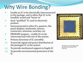
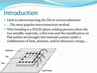

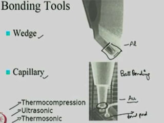
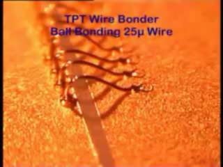

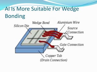

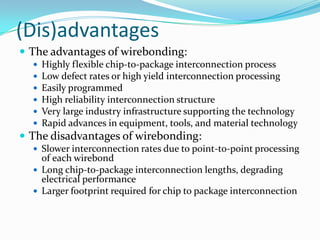


Wire bonding is used to electrically interconnect integrated circuits to packages so they can be handled, tested, and used in electronic products. There are two main types of wire bonding: ball bonding and wedge bonding. Ball bonding uses a capillary tool to form a ball bond on the chip and substrate, while wedge bonding uses a wedge tool. Wire bonding allows for high-speed, economical connections and is the most common interconnection method. It enables signals and power to be distributed from the packaged IC to the rest of the system while also providing mechanical support and environmental protection.