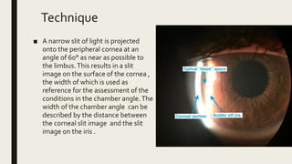
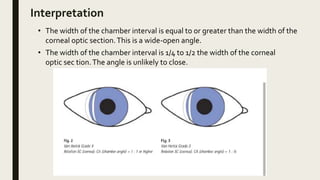
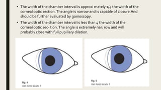
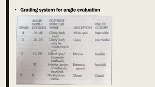
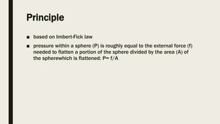
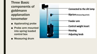
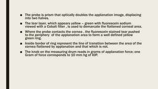
VAN HERICK ANGLE
ESTIMATION
Dr. Priyanka Sorathiya
1st year resident
Department of ophthlmology
Indication
■ To assess the depth of anterior chamber with slit
lamp without using gonioscopc lens
■ Routine comprehensive slit lamp examination
Slit lamp set up for van herick angle
estimation
• Beam angle : 60 degree
• Beam height : maximum
• Filter : none
• Illumination : medium
• Magnification : 10- 16 X
Technique
■ A narrow slit of light is projected
onto the peripheral cornea at an
angle of 60° as near as possible to
the limbus.This results in a slit
image on the surface of the cornea ,
the width of which is used as
reference for the assessment of the
conditions in the chamber angle.The
width of the chamber angle can be
described by the distance between
the corneal slit image and the slit
image on the iris .
Interpretation
• The width of the chamber interval is equal to or greater than the width of the
corneal optic section.This is a wide-open angle.
• The width of the chamber interval is 1/4 to 1/2 the width of the corneal
optic sec tion.The angle is unlikely to close.
• The width of the chamber interval is approxi mately 1/4 the width of the
corneal optic section.The angle is narrow and is capable of closure.And
should be further evaluated by gonioscopy.
• The width of the chamber interval is less than 4 the width of the
corneal optic sec- tion.The angle is extremely nar: row and will
probably close with full pupillary dilation.
• Complications
Peripheral corneal conditions such as arcus senilis may make it diffi cult to
gauge if the optic section is positioned correctly at the limbus, or may make
visualization of the anterior cham ber interval difficult. Gonioscopy may then
be necessary to fully evaluate the anterior chamber angle.
Gonioscopy
Three mirror lens
Description
• Gonioscopy is a technique used to visualize and assess the anterior
chamber angle.
• A gonioscopic lens is a plastic cone-shaped contact lens containing
reflecting mirrors that is used in conjunction with the slit lamp
biomicroscope to evaluate the anterior chamber angle. Gonioscopic lenses
come in various sizes and designs, containing one, two, or three mirrors .
The most commonly used lens is the three-mirror universal (Goldmann)
design, which allows for evaluation of the angle, as well as the posterior
pole and the mid and far peripheral retina .
• A coupling solution is required for use with a three-mirror lens.
Indication
• glaucoma suspects or ocular hypertensives; accurately diagnos ing
open or narrow-angle glaucoma;
• assessing angle pigmentation; assessing the angle as suitable for pupillary
dilation in suspiciously narrow cases previously evaluated withVan Herick
angle estimation
Technique
• Instill gonioscopic fluid into the concave surface of the goniolens .
• Instill two drops of a topical ophthalmic anesthetic solution in each eye.
• Advise the patient that a mild, transient burning sensation may occur.
• Adjust the room illumination dark with little ambient light.
• Adjust the slit lamp magnification to 10X.Adjust the beam width to approximately
4 mm.
• To insert the goniolens in the right eye, position your self slightly to the
patient's right and move the slit lamp all the way to the patient's left.
• Ask the patient to look up and use the forefinger or thumb of your left hand to
gently retract the patient's lower lid. With your right hand place one edge of the
slightly tilted goniolens into the inferior fornix and release the lower lid.
• Use the thumb of your left hand to gently but firmly grasp the right upper lid as
the patient continues to look up . Ask the patient to look straight ahead . Quickly
pivot the goniolens onto the comea and release the upper lid. Exchange hands so
that the thumb and forefinger of your left hand are holding the edge of the
goniolens.
• Increase the magnification to 16X to assess the angle structures.The inferior angle will
be viewed which in most eyes is the widest, giving the clinician a baseline with which
to evaluate the other quadrants.
• The slit beam may be narrowed to an optic section and moved to create an
angle of approximately 45 degrees from the micro scope.
• Assess the pupil frill of the iris initially and then follow the slit beam as it rolls
along the iris surface and struetures of the anterior chamber angle.
• The semicircular mirror of the goniolens is typically placed superiorly initially to
analyze the inferior angle. Because this portion of the angle is the largest,
• To remove the goniolens, ask the patient to squeeze the lids shut and the lens
should pop off the eye.
Interpretation
• The three-mirror goniolens uses a mirror to indirectly visualize the angle,
the gonioscopic image will be 180 degrees away from the mirror
position.
• The assessment includes evaluation of the angle made between the
anterior surface of the iris and the posterior surface of the cornea
• The most commonly used angle grading system incorporates grades
of 0 to 4
• The iris is evaluated at the onset of the procedure.
• The ciliary body will appear as a light gray to brown band just anterior
to root of Iris.
• The scleral spur is just anterior to the ciliary body and appears as
thin white band
• The trabecular meshwork is the next
tissue observed , varying in color
from tan to dark brown. Aqueous
humor flows through the posterior
portion of the trabecular meshwork.
• Schlemm’s canal located within
the posterior portion of
trabecular meshwork and
usually not visible except when
blood or pigment present.
• The most anterior structure of the
angle is Schwalbe's line. which marks
the end of the comea and is seen as a
thin, refractile white line.
• Grading system for angle evaluation
Complications
■ Induce transient superficial punctate keratitis
■ Transient foreign body sensation
GOLDMAN’S APPLANATION
TONOMETRY
Introduction
• measures IOP by providing force which flattens the
cornea.
Principle
■ based on Imbert-Fick law
■ pressure within a sphere (P) is roughly equal to the external force (f)
needed to flatten a portion of the sphere divided by the area (A) of
the spherewhich is flattened: P= f/A
Three Basic
components of
goldmann
applanation
tonometer
■ Applanating probe
■ Probe arm mounted
into spring loaded
control box
■ Measuring drum
■ The probe is prism that optically doubles the applanation image, displacing
into two halves.
■ The tear layer, which appears yellow – green with fluorescein sodium
viewed with a Cobalt filter , is used to demarcate the flattened corneal area.
■ Where the probe contacts the cornea , the fluorescein stained tear pushed
to the periphery of the applanation area to form a well defined yellow
green ring.
■ Inside border of ring represent the line of transition between the area of the
cornea flattened by applanation and that which is not.
■ The knob on the measuring drum reads in grams of applanation force; one
Gram of force corresponds to 10 mm hg of IOP.
Technique
■ Patient is told the purpose of the test and is reassured that the
measurement is not painful.
■ The patient is instructed to relax, maintain position, and hold the
eyes open wide.
■ One drop of a topical anesthetic, such as 0.5% proparacaine, is
placed in each eye, and the tip of a moistened fluorescein strip is
touched to the tear layer on the inner surface of each lower lid.
■ Tonometer tip is cleaned with a sterilizing solution, and the tip and
prism are set in correct position on the slit lamp.
• Position the slit lamp illumination source approximately 60
degrees from the eyepieces. Open the slit beam to its widest
setting and introduce the cobalt filter. Set the slit lamp
magnification to 6X to 10X,
• Looking outside the slit lamp. grossly center the probe approximately
3/4 inch from the right corneal apex
• Instruct the patient to fixate straight ahead or adjust the fixation light so
that the right eye is in primary gaze.
• Looking through the slit lamp, use the joystick to move the probe slightly
forward. Approximately 1½ inch before corneal contact is made, the
reflection of the probe off the cornea will appear as two pale blue semicircles.
• Use the joystick to move the probe toward the corneal apex while
maintaining centration of the pale blue semicircles as visualized through the
slit lamp.
• While maintaining applanation with one hand on the joystick, quickly
use the opposite hand to turn the measuring drum until the inner
borders of the two fluorescein semicircles just touch each other.
Gonioscopy

Gonioscopy

  • 1.
    VAN HERICK ANGLE ESTIMATION Dr.Priyanka Sorathiya 1st year resident Department of ophthlmology
  • 2.
    Indication ■ To assessthe depth of anterior chamber with slit lamp without using gonioscopc lens ■ Routine comprehensive slit lamp examination
  • 3.
    Slit lamp setup for van herick angle estimation • Beam angle : 60 degree • Beam height : maximum • Filter : none • Illumination : medium • Magnification : 10- 16 X
  • 4.
    Technique ■ A narrowslit of light is projected onto the peripheral cornea at an angle of 60° as near as possible to the limbus.This results in a slit image on the surface of the cornea , the width of which is used as reference for the assessment of the conditions in the chamber angle.The width of the chamber angle can be described by the distance between the corneal slit image and the slit image on the iris .
  • 5.
    Interpretation • The widthof the chamber interval is equal to or greater than the width of the corneal optic section.This is a wide-open angle. • The width of the chamber interval is 1/4 to 1/2 the width of the corneal optic sec tion.The angle is unlikely to close.
  • 6.
    • The widthof the chamber interval is approxi mately 1/4 the width of the corneal optic section.The angle is narrow and is capable of closure.And should be further evaluated by gonioscopy. • The width of the chamber interval is less than 4 the width of the corneal optic sec- tion.The angle is extremely nar: row and will probably close with full pupillary dilation.
  • 7.
    • Complications Peripheral cornealconditions such as arcus senilis may make it diffi cult to gauge if the optic section is positioned correctly at the limbus, or may make visualization of the anterior cham ber interval difficult. Gonioscopy may then be necessary to fully evaluate the anterior chamber angle.
  • 8.
  • 9.
    Description • Gonioscopy isa technique used to visualize and assess the anterior chamber angle. • A gonioscopic lens is a plastic cone-shaped contact lens containing reflecting mirrors that is used in conjunction with the slit lamp biomicroscope to evaluate the anterior chamber angle. Gonioscopic lenses come in various sizes and designs, containing one, two, or three mirrors . The most commonly used lens is the three-mirror universal (Goldmann) design, which allows for evaluation of the angle, as well as the posterior pole and the mid and far peripheral retina . • A coupling solution is required for use with a three-mirror lens.
  • 10.
    Indication • glaucoma suspectsor ocular hypertensives; accurately diagnos ing open or narrow-angle glaucoma; • assessing angle pigmentation; assessing the angle as suitable for pupillary dilation in suspiciously narrow cases previously evaluated withVan Herick angle estimation
  • 11.
    Technique • Instill gonioscopicfluid into the concave surface of the goniolens . • Instill two drops of a topical ophthalmic anesthetic solution in each eye. • Advise the patient that a mild, transient burning sensation may occur. • Adjust the room illumination dark with little ambient light. • Adjust the slit lamp magnification to 10X.Adjust the beam width to approximately 4 mm. • To insert the goniolens in the right eye, position your self slightly to the patient's right and move the slit lamp all the way to the patient's left. • Ask the patient to look up and use the forefinger or thumb of your left hand to gently retract the patient's lower lid. With your right hand place one edge of the slightly tilted goniolens into the inferior fornix and release the lower lid.
  • 12.
    • Use thethumb of your left hand to gently but firmly grasp the right upper lid as the patient continues to look up . Ask the patient to look straight ahead . Quickly pivot the goniolens onto the comea and release the upper lid. Exchange hands so that the thumb and forefinger of your left hand are holding the edge of the goniolens.
  • 13.
    • Increase themagnification to 16X to assess the angle structures.The inferior angle will be viewed which in most eyes is the widest, giving the clinician a baseline with which to evaluate the other quadrants. • The slit beam may be narrowed to an optic section and moved to create an angle of approximately 45 degrees from the micro scope. • Assess the pupil frill of the iris initially and then follow the slit beam as it rolls along the iris surface and struetures of the anterior chamber angle. • The semicircular mirror of the goniolens is typically placed superiorly initially to analyze the inferior angle. Because this portion of the angle is the largest, • To remove the goniolens, ask the patient to squeeze the lids shut and the lens should pop off the eye.
  • 14.
    Interpretation • The three-mirrorgoniolens uses a mirror to indirectly visualize the angle, the gonioscopic image will be 180 degrees away from the mirror position. • The assessment includes evaluation of the angle made between the anterior surface of the iris and the posterior surface of the cornea • The most commonly used angle grading system incorporates grades of 0 to 4 • The iris is evaluated at the onset of the procedure. • The ciliary body will appear as a light gray to brown band just anterior to root of Iris. • The scleral spur is just anterior to the ciliary body and appears as thin white band
  • 15.
    • The trabecularmeshwork is the next tissue observed , varying in color from tan to dark brown. Aqueous humor flows through the posterior portion of the trabecular meshwork. • Schlemm’s canal located within the posterior portion of trabecular meshwork and usually not visible except when blood or pigment present. • The most anterior structure of the angle is Schwalbe's line. which marks the end of the comea and is seen as a thin, refractile white line.
  • 16.
    • Grading systemfor angle evaluation
  • 17.
    Complications ■ Induce transientsuperficial punctate keratitis ■ Transient foreign body sensation
  • 18.
  • 19.
    Introduction • measures IOPby providing force which flattens the cornea.
  • 20.
    Principle ■ based onImbert-Fick law ■ pressure within a sphere (P) is roughly equal to the external force (f) needed to flatten a portion of the sphere divided by the area (A) of the spherewhich is flattened: P= f/A
  • 21.
    Three Basic components of goldmann applanation tonometer ■Applanating probe ■ Probe arm mounted into spring loaded control box ■ Measuring drum
  • 22.
    ■ The probeis prism that optically doubles the applanation image, displacing into two halves. ■ The tear layer, which appears yellow – green with fluorescein sodium viewed with a Cobalt filter , is used to demarcate the flattened corneal area. ■ Where the probe contacts the cornea , the fluorescein stained tear pushed to the periphery of the applanation area to form a well defined yellow green ring. ■ Inside border of ring represent the line of transition between the area of the cornea flattened by applanation and that which is not. ■ The knob on the measuring drum reads in grams of applanation force; one Gram of force corresponds to 10 mm hg of IOP.
  • 23.
    Technique ■ Patient istold the purpose of the test and is reassured that the measurement is not painful. ■ The patient is instructed to relax, maintain position, and hold the eyes open wide. ■ One drop of a topical anesthetic, such as 0.5% proparacaine, is placed in each eye, and the tip of a moistened fluorescein strip is touched to the tear layer on the inner surface of each lower lid. ■ Tonometer tip is cleaned with a sterilizing solution, and the tip and prism are set in correct position on the slit lamp. • Position the slit lamp illumination source approximately 60 degrees from the eyepieces. Open the slit beam to its widest setting and introduce the cobalt filter. Set the slit lamp magnification to 6X to 10X,
  • 24.
    • Looking outsidethe slit lamp. grossly center the probe approximately 3/4 inch from the right corneal apex • Instruct the patient to fixate straight ahead or adjust the fixation light so that the right eye is in primary gaze. • Looking through the slit lamp, use the joystick to move the probe slightly forward. Approximately 1½ inch before corneal contact is made, the reflection of the probe off the cornea will appear as two pale blue semicircles. • Use the joystick to move the probe toward the corneal apex while maintaining centration of the pale blue semicircles as visualized through the slit lamp. • While maintaining applanation with one hand on the joystick, quickly use the opposite hand to turn the measuring drum until the inner borders of the two fluorescein semicircles just touch each other.