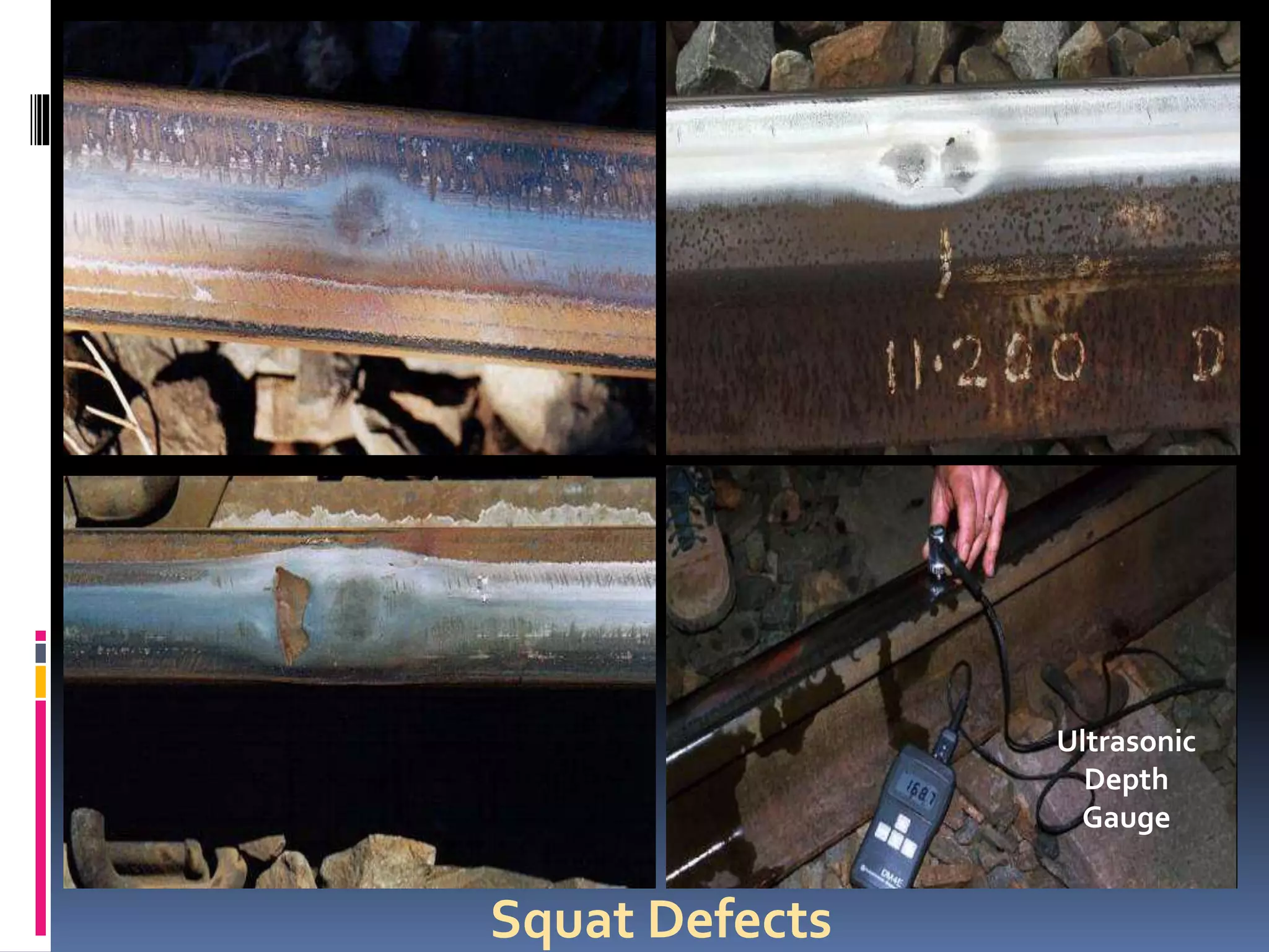
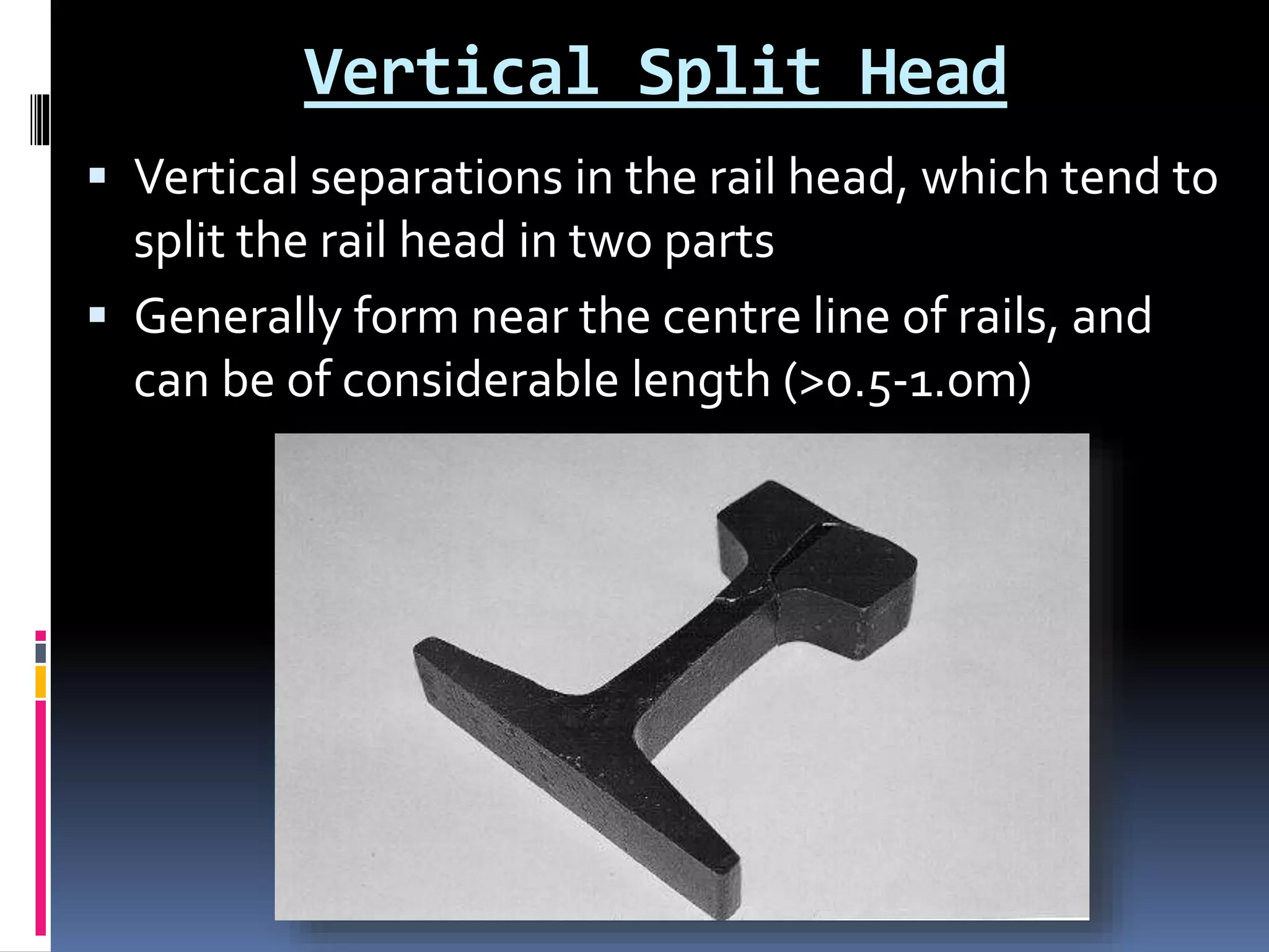
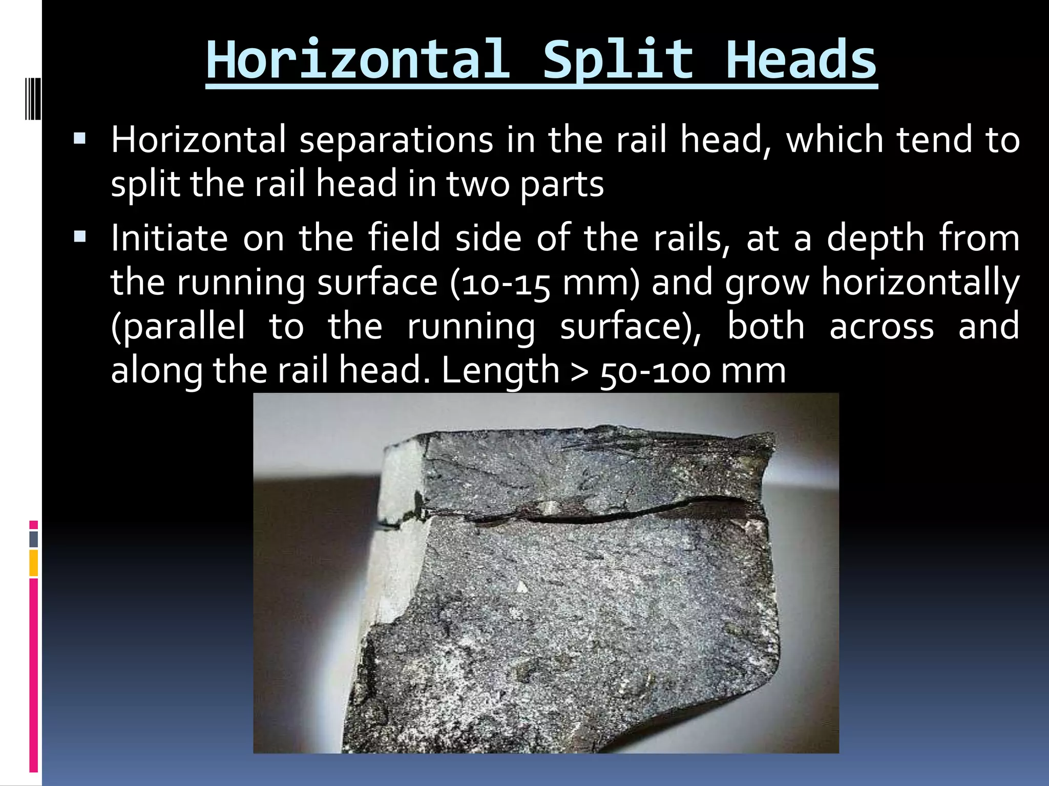
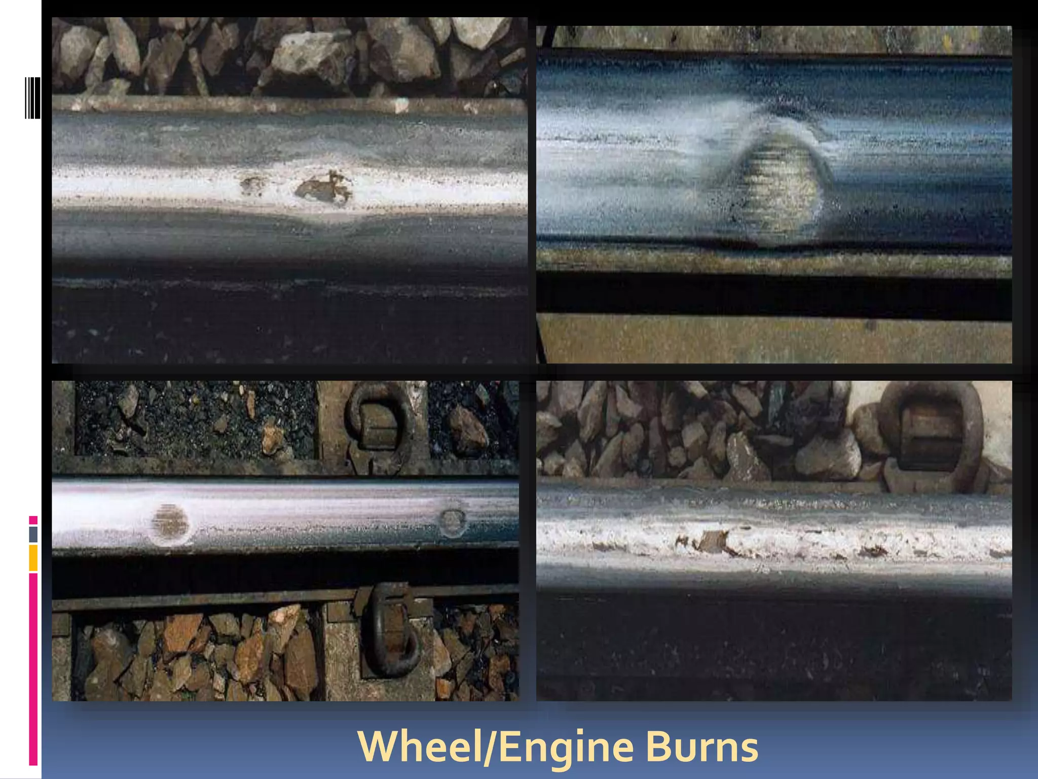
DEFECTS IN A RAILWAY TRACK
&
THEIR MAINTENANCE
Prof. Suhas R
Asst. Professor,
Department of ConstructionTechnology Management
&
HighwayTechnology
Dayananda Sagar College of Engineering
Facts about Indian Railways
 Largest in Asia; 4th largest in the world, following US,
China & Russia
 20 – 25 million passengers commute daily
 8th largest employer in the world with over 1.5 million
employees , following United States Department of
Defense, People’s Liberation Army (China) & WALMART at
the top three
 Fastest Train in India - The New Delhi Bhopal Shatabdhi
Express is the fastest train in India with the top speed of
150 kmph (93 mph)
 Longest train in India - Dibrugarh - Kanyakumari Vivek
Express – 4273 km – 79 Hours of journey – 57 stops
 Mughalsarai Junction railway station contains the largest
railway marshaling yard in Asia
 The Rajdhani Express trains get the highest priority on the
Indian railway network
Facts..... Contd....
 Longest platforms in the world:
 Gorakhpur railway station, Uttar Pradesh, India:1,366.33 m
(4,483 ft) (longest in the world)
 Kollam Junction, Kerala, India:1,180.5 m (3,873 ft)
 Kharagpur,West Bengal, India: 1,072.5 m (3,519 ft)
 The Fairy Queen (East Indian Railway Nr. 22) - 1855-
built steam locomotive - occasionally runs between
New Delhi and Alwar
 Chenab Bridge- Steel and Concrete Arch bridge -
Bakkal and Kauri in the Reasi district of Jammu and
Kashmir – Height 359 m above the river - world's
highest rail bridge
 Loco-pilots are paid more than an average software
engineer in India – haa haa haa haa….
 If the tracks of Indian railways were to be laid out,
they would circle the earth almost 1.5 times
 The Rajdhani Express trains get the highest
priority on the Indian railway network
 The IRCTC (Indian Railways Catering & Tourism
Corporation) website gets close to 12 lakh hits per
minute
 World Heritage sites 4 Indian Railways sites and 5
Mountain Railways.
 The New Delhi Main Station, having the world's
largest route relay interlocking system, has a place
in the Guinness Book of Records.
Facts..... Contd....
Loads & Stresses on Rails
 Loads:
 Vertical Loading - forces applied by the wheel tread under
normal train operation
 Lateral Loading - forces applied by the wheel flange to the
high rail in curved track
 Creep - forces that are generated at the rail/wheel interface by
the rolling action of the wheel
 Stresses
 Bending - bending of the rail that occurs from vertical or
lateral wheel loading
 Thermal - occurs in continuous welded rails due to thermal
expansion and contractions (when actual rail temperature
increases above or below the rail neutral temperature)
 Residual - a result of the manufacturing process, particularly
from roller straightening and head hardening
Defects in Rails - Introduction
 All major rail defects require some form of stress to initiate and
develop
Longitudinal direction Along the rail
Transverse direction Across the rail
Vertical direction Normal to the rail
Vertical plane Vertical along the rail
Horizontal plane Horizontal along the rail
Transverse plane Transverse across the rail
Common defects in Railway Tracks
 Rail Corrugations
 Rolling Contact Fatigue Defects
 Squat Defects
 Shatter Cracking
 Vertical Split Head
 Horizontal Split Head
 Wheel Engine Burns
 Other Defects
 Rail Head Defects
 Web defects
 Foot defects
 Defects due to rail damage
 Weld defects
Rail Corrugations
 Rail corrugations are cyclic (wave-like), generally
vertical, irregularities on the running surface of the
rails
 Corrugations are of two main types:
 Short pitch
 30mm to 90mm in wavelength
 Develop under lighter nominal axle load (< 20 tonnes)
passenger operations
 Depth - less than 0.2-0.3mm.
 Long pitch
 300mm in wavelength
 Develop under higher nominal axle load (> 20 tonnes) mixed
freight or unit train operations
 Depth from 0.1mm to above 2.0mm
 Note: Some long wavelength track defects are sometimes occur due to cyclic
differences in track rigidity such as can arise particularly with different sleeper
types.These should not be mistaken for corrugations.
Long Pitch Corrugations
Short Pitch Corrugations
Causes
 Sort Pitch
 By the differential wear caused by a repetitious longitudinal
sliding action of the wheel on the rail, whether through
acceleration, braking or lateral motion across the rail
 Long Pitch
 develop because of the plastic flow of the rail material that is
due to excessive wheel/rail contact stresses and the
combined vertical resonance of the wheel-set un-sprung
mass and the track
 The long pitch corrugations are sometimes observed
on the low rails of curves, sometimes on the high rails,
and sometimes on both. This is mainly a function of
the super-elevation of the track, which may lead to
the loading of one rail more than the other
Factors which lead to higher dynamic
loadings
 Higher nominal wheel loads
 Higher vehicle speeds, which increase the dynamic loads
 Larger vertical dips at welds/joints, which increase the impact
loads
 Higher track stiffnesses (concrete sleepers are much stiffer than
timber sleepers), which increase the dynamic/impact loads
 Higher rail pad stiffnesses, which increase the dynamic/impact
loads
 Higher bogie suspension stiffnesses, which increase the
dynamic/impact loads
 Smaller wheel radii, which increase the wheel/rail contact stresses
 Higher friction/creep at the wheel/rail contact
 Softer rails, which increase the propensity for plastic flow of the
material
 Poor matching of wheel and rail profiles, which leads to narrow
wheel/rail contact and hence higher contact stresses
Effects of Corrugations
 Increase the dynamic wheel loads (and vibration), and
therefore the rate of deterioration and failure of various
track and vehicle components, such as:
 Rails and defects (such as shelling).
 Welds
 Bolt holes at insulated rail joints
 Rail pads
 Sleepers, particularly in the rail seat region
 Ballast, which tends to powder and become rounded
 Rail clips (which also become loose)
 Track geometry (mainly because of the vibration and the ballast
deterioration). Indeed, corrugations can lead to the skewing of
sleepers
 Wheels and defects
 Bearings
 Bridges and abutments, particularly when the track is not
ballasted
Treatment
 Use of higher strength (mainly heat treated) rail steels,
particularly in sharper curves that are more sensitive to
corrugation development.
 Application of improved wheel and rail profiles, which
reduce the wheel/rail contact stresses
 The aim of the improved profiles is to produce a
relatively large and conformal contact band, rather than
narrow contact bands that lead to very high contact
stresses, and consequently enhance corrugation
development
 Wheel and rail profiles can also be designed to improve
the dynamic characteristics (hunting) of wheel-
sets/bogies, particularly in the shallower curves, and
hence reduce the creep forces at the wheel/rail interface
Treatment (Contd....)
 Application of regular rail maintenance in the form
of grinding, to control the growth of corrugations.
Rail grinding is also required to implement the
improve
 Reducing the track stiffness characteristics, with
the implementation of softer and thicker rail pads,
may also inhibit corrugation development
Rolling Contact Fatigue Defects
 The term rolling contact fatigue is generic in
nature and used to describe a range of defects
that are due, basically, to the development of
excessive/repetitive shear stresses at the
wheel/rail contact interface
 ThreeTypes:
 Gauge Corner Checking
 Shelling
 Running Surface Checking
Gauge Corner Checking
Shelling
Running Surface Checking
Causes
 Both checking (gauge corner and running surface)
and shelling defects are initiated by - the high
shear stresses that can develop at the wheel/rail
contact region when such stresses exceed the
allowable limits for the rail material
Treatment
 Higher strength rail steels
 Improvements in the cleanliness of the rail steels
 Improvements in the wheel/rail lubrication
procedures
 Application of appropriate rail maintenance
strategies
 Improvements in the wheel/rail interaction
characteristics
 Application of suitable ultrasonic testing
procedures
 Improvements in the rail field stressing procedures
Squat Defects
 Subsurface laminations which initiate at small cracks,
thought to be at the rail surface
 2Types
 Running surface squats
 Gauge corner squats
 Squats are indicated by a darkened area in the contact
band, which results from a depression in the rail
surface and reduced polishing by train wheels
 Squats can occur in irregular patterns on one rail only
or in both rails. In some cases on tangent track, the
same pattern of squats is repeated on both rails,
suggesting initiation associated with a particular
wheelset
Squat Defects
Ultrasonic
Depth
Gauge
Treatment
 Three Methods
 Head repair welding using the wire feed process
 Re-railing
 Rail grinding
 Regular cyclic rail grinding
 Adjustments to the rail profiles to broaden the
contact band and reduce rail stress
 Early intervention and increased depth of grinding
when wheel-slip is identified
 Increasing the depth of grind at locations when
squats are first identified
Shatter Cracking
 Also known asTransverse Fissures
 Internal defects that initiate near the centre of the
rail head, and grow transversely
 As for transverse defects, because of their internal
nature, Shatter Cracking cannot be visually
detected, and hence must rely on regular
ultrasonic rail inspection
Shatter Cracking
Causes
 The initiation of Shatter Crack defects is due to the
presence of excessive levels of hydrogen in rail steel (or
welds)
 While manufacturing rails, the steel blooms from which
the rails are made or even the rails are slowly cooled over
a long time to allow most of the hydrogen to diffuse out of
the steel
 If, however, the slow cooling process is inefficient, some
hydrogen remains in the steel
 The hydrogen atoms combine at preferred sites, such as
grain boundaries or inclusions, and form molecular
hydrogen
 This process leads to marked increases in the internal
pressure associated with the pockets of molecular
hydrogen, which greatly enhances the risk of crack
initiation
Treatment
 The principal treatment for Shatter Crack defects
is to reduce the critical hydrogen content of the
steel, by appropriate steelmaking and/or heat
treatment procedures
 Replacement with good quality Rails
Vertical Split Head
 Vertical separations in the rail head, which tend to
split the rail head in two parts
 Generally form near the centre line of rails, and
can be of considerable length (>0.5-1.0m)
Causes
 Initiate at Elongated seams, Inclusion stringers or
highly segregated regions
 Occur particularly in the older rails produced by
means of ingots (rather than the current
continuous casting), which generally exhibited
much higher levels of irregularities
Treatment
 The improved cleanliness associated with the newer
rails reduces considerably the risk of defect
development
 The ultrasonic procedures adopted by rail
manufacturers must also exhibit sufficient accuracy to
allow the detection of any elongated seams or large
inclusions within the rail head
 Reducing the levels of wheel hollowing, so that off
centre loading of the rails is minimized
 Grinding the rails, so that the wheel loading is
concentrated near the centre of the running surface
 Regular ultrasonic rail testing must be carried out to
detect the vertical split heads before they reach a
critical size, which may cause rail failure.
Horizontal Split Heads
 Horizontal separations in the rail head, which tend to
split the rail head in two parts
 Initiate on the field side of the rails, at a depth from
the running surface (10-15 mm) and grow horizontally
(parallel to the running surface), both across and
along the rail head. Length > 50-100 mm
Causes
 Horizontal split heads initiate at elongated seams
or inclusion stringers, which may be present in the
rails, in the same way as vertical split heads
Treatment
 Same as that ofVertical Split Head
Wheel/Engine Burns
 Wheel-burns are defects that form on the running
surface of the rails.
 Small wheel burns are very similar in appearance
to small squats
 Unlike squats which can form at discrete locations,
wheel burns always occur in pairs directly opposite
to each other on the two rails
 Severe wheel-burns, which can be more than 50
mm in length, exhibit what seem to be
longitudinal gouging marks on their surface.
 Wheel-burns can also occur while the locomotives
are in motion
Wheel/Engine Burns
Causes
 Wheel-burn defects are caused by the continuous
slipping of the locomotive wheels on the rails. This
occurs when the longitudinal creep reaches saturation
 Excessive track grades
 Poor train driving procedures, such as rapid
acceleration
 Insufficient locomotive power
 Contamination of the running surface of the rails,
which can reduce the friction to undesirable levels
(less than about 0.30-0.35). This may occur when the
rail lubrication is not applied efficiently, particularly
close to track mounted lubricators
Treatment
 The influencing operational factors are minimized
 The wheel/rail lubricant does not contaminate the
running surface of the rails
 Positioning of lubricators next to relatively medium
and shallow curves (with radii in the range 400-
1000m), rather than next to sharp curves or in tangent
track
 Ensuring that excessive lubricant is not being pumped
out
 Separating the lubricators on the Up and Down rails
by a distance of at least 500 m and preferably 1 km
 Regular ultrasonic rail testing procedures must be
capable of detecting the transverse defects below the
wheel burns before they reach a critical size, which
may cause rail failure
Defects in a Railway Track & their maintenance.pptx

Defects in a Railway Track & their maintenance.pptx

  • 1.
    DEFECTS IN ARAILWAY TRACK & THEIR MAINTENANCE Prof. Suhas R Asst. Professor, Department of ConstructionTechnology Management & HighwayTechnology Dayananda Sagar College of Engineering
  • 2.
    Facts about IndianRailways  Largest in Asia; 4th largest in the world, following US, China & Russia  20 – 25 million passengers commute daily  8th largest employer in the world with over 1.5 million employees , following United States Department of Defense, People’s Liberation Army (China) & WALMART at the top three  Fastest Train in India - The New Delhi Bhopal Shatabdhi Express is the fastest train in India with the top speed of 150 kmph (93 mph)  Longest train in India - Dibrugarh - Kanyakumari Vivek Express – 4273 km – 79 Hours of journey – 57 stops  Mughalsarai Junction railway station contains the largest railway marshaling yard in Asia  The Rajdhani Express trains get the highest priority on the Indian railway network
  • 3.
    Facts..... Contd....  Longestplatforms in the world:  Gorakhpur railway station, Uttar Pradesh, India:1,366.33 m (4,483 ft) (longest in the world)  Kollam Junction, Kerala, India:1,180.5 m (3,873 ft)  Kharagpur,West Bengal, India: 1,072.5 m (3,519 ft)  The Fairy Queen (East Indian Railway Nr. 22) - 1855- built steam locomotive - occasionally runs between New Delhi and Alwar  Chenab Bridge- Steel and Concrete Arch bridge - Bakkal and Kauri in the Reasi district of Jammu and Kashmir – Height 359 m above the river - world's highest rail bridge  Loco-pilots are paid more than an average software engineer in India – haa haa haa haa….
  • 4.
     If thetracks of Indian railways were to be laid out, they would circle the earth almost 1.5 times  The Rajdhani Express trains get the highest priority on the Indian railway network  The IRCTC (Indian Railways Catering & Tourism Corporation) website gets close to 12 lakh hits per minute  World Heritage sites 4 Indian Railways sites and 5 Mountain Railways.  The New Delhi Main Station, having the world's largest route relay interlocking system, has a place in the Guinness Book of Records. Facts..... Contd....
  • 5.
    Loads & Stresseson Rails  Loads:  Vertical Loading - forces applied by the wheel tread under normal train operation  Lateral Loading - forces applied by the wheel flange to the high rail in curved track  Creep - forces that are generated at the rail/wheel interface by the rolling action of the wheel  Stresses  Bending - bending of the rail that occurs from vertical or lateral wheel loading  Thermal - occurs in continuous welded rails due to thermal expansion and contractions (when actual rail temperature increases above or below the rail neutral temperature)  Residual - a result of the manufacturing process, particularly from roller straightening and head hardening
  • 6.
    Defects in Rails- Introduction  All major rail defects require some form of stress to initiate and develop Longitudinal direction Along the rail Transverse direction Across the rail Vertical direction Normal to the rail Vertical plane Vertical along the rail Horizontal plane Horizontal along the rail Transverse plane Transverse across the rail
  • 7.
    Common defects inRailway Tracks  Rail Corrugations  Rolling Contact Fatigue Defects  Squat Defects  Shatter Cracking  Vertical Split Head  Horizontal Split Head  Wheel Engine Burns  Other Defects  Rail Head Defects  Web defects  Foot defects  Defects due to rail damage  Weld defects
  • 8.
    Rail Corrugations  Railcorrugations are cyclic (wave-like), generally vertical, irregularities on the running surface of the rails  Corrugations are of two main types:  Short pitch  30mm to 90mm in wavelength  Develop under lighter nominal axle load (< 20 tonnes) passenger operations  Depth - less than 0.2-0.3mm.  Long pitch  300mm in wavelength  Develop under higher nominal axle load (> 20 tonnes) mixed freight or unit train operations  Depth from 0.1mm to above 2.0mm  Note: Some long wavelength track defects are sometimes occur due to cyclic differences in track rigidity such as can arise particularly with different sleeper types.These should not be mistaken for corrugations.
  • 9.
  • 10.
    Causes  Sort Pitch By the differential wear caused by a repetitious longitudinal sliding action of the wheel on the rail, whether through acceleration, braking or lateral motion across the rail  Long Pitch  develop because of the plastic flow of the rail material that is due to excessive wheel/rail contact stresses and the combined vertical resonance of the wheel-set un-sprung mass and the track  The long pitch corrugations are sometimes observed on the low rails of curves, sometimes on the high rails, and sometimes on both. This is mainly a function of the super-elevation of the track, which may lead to the loading of one rail more than the other
  • 11.
    Factors which leadto higher dynamic loadings  Higher nominal wheel loads  Higher vehicle speeds, which increase the dynamic loads  Larger vertical dips at welds/joints, which increase the impact loads  Higher track stiffnesses (concrete sleepers are much stiffer than timber sleepers), which increase the dynamic/impact loads  Higher rail pad stiffnesses, which increase the dynamic/impact loads  Higher bogie suspension stiffnesses, which increase the dynamic/impact loads  Smaller wheel radii, which increase the wheel/rail contact stresses  Higher friction/creep at the wheel/rail contact  Softer rails, which increase the propensity for plastic flow of the material  Poor matching of wheel and rail profiles, which leads to narrow wheel/rail contact and hence higher contact stresses
  • 12.
    Effects of Corrugations Increase the dynamic wheel loads (and vibration), and therefore the rate of deterioration and failure of various track and vehicle components, such as:  Rails and defects (such as shelling).  Welds  Bolt holes at insulated rail joints  Rail pads  Sleepers, particularly in the rail seat region  Ballast, which tends to powder and become rounded  Rail clips (which also become loose)  Track geometry (mainly because of the vibration and the ballast deterioration). Indeed, corrugations can lead to the skewing of sleepers  Wheels and defects  Bearings  Bridges and abutments, particularly when the track is not ballasted
  • 13.
    Treatment  Use ofhigher strength (mainly heat treated) rail steels, particularly in sharper curves that are more sensitive to corrugation development.  Application of improved wheel and rail profiles, which reduce the wheel/rail contact stresses  The aim of the improved profiles is to produce a relatively large and conformal contact band, rather than narrow contact bands that lead to very high contact stresses, and consequently enhance corrugation development  Wheel and rail profiles can also be designed to improve the dynamic characteristics (hunting) of wheel- sets/bogies, particularly in the shallower curves, and hence reduce the creep forces at the wheel/rail interface
  • 14.
    Treatment (Contd....)  Applicationof regular rail maintenance in the form of grinding, to control the growth of corrugations. Rail grinding is also required to implement the improve  Reducing the track stiffness characteristics, with the implementation of softer and thicker rail pads, may also inhibit corrugation development
  • 15.
    Rolling Contact FatigueDefects  The term rolling contact fatigue is generic in nature and used to describe a range of defects that are due, basically, to the development of excessive/repetitive shear stresses at the wheel/rail contact interface  ThreeTypes:  Gauge Corner Checking  Shelling  Running Surface Checking
  • 16.
  • 17.
  • 18.
  • 19.
    Causes  Both checking(gauge corner and running surface) and shelling defects are initiated by - the high shear stresses that can develop at the wheel/rail contact region when such stresses exceed the allowable limits for the rail material
  • 20.
    Treatment  Higher strengthrail steels  Improvements in the cleanliness of the rail steels  Improvements in the wheel/rail lubrication procedures  Application of appropriate rail maintenance strategies  Improvements in the wheel/rail interaction characteristics  Application of suitable ultrasonic testing procedures  Improvements in the rail field stressing procedures
  • 21.
    Squat Defects  Subsurfacelaminations which initiate at small cracks, thought to be at the rail surface  2Types  Running surface squats  Gauge corner squats  Squats are indicated by a darkened area in the contact band, which results from a depression in the rail surface and reduced polishing by train wheels  Squats can occur in irregular patterns on one rail only or in both rails. In some cases on tangent track, the same pattern of squats is repeated on both rails, suggesting initiation associated with a particular wheelset
  • 22.
  • 23.
    Treatment  Three Methods Head repair welding using the wire feed process  Re-railing  Rail grinding  Regular cyclic rail grinding  Adjustments to the rail profiles to broaden the contact band and reduce rail stress  Early intervention and increased depth of grinding when wheel-slip is identified  Increasing the depth of grind at locations when squats are first identified
  • 24.
    Shatter Cracking  Alsoknown asTransverse Fissures  Internal defects that initiate near the centre of the rail head, and grow transversely  As for transverse defects, because of their internal nature, Shatter Cracking cannot be visually detected, and hence must rely on regular ultrasonic rail inspection
  • 25.
  • 26.
    Causes  The initiationof Shatter Crack defects is due to the presence of excessive levels of hydrogen in rail steel (or welds)  While manufacturing rails, the steel blooms from which the rails are made or even the rails are slowly cooled over a long time to allow most of the hydrogen to diffuse out of the steel  If, however, the slow cooling process is inefficient, some hydrogen remains in the steel  The hydrogen atoms combine at preferred sites, such as grain boundaries or inclusions, and form molecular hydrogen  This process leads to marked increases in the internal pressure associated with the pockets of molecular hydrogen, which greatly enhances the risk of crack initiation
  • 27.
    Treatment  The principaltreatment for Shatter Crack defects is to reduce the critical hydrogen content of the steel, by appropriate steelmaking and/or heat treatment procedures  Replacement with good quality Rails
  • 28.
    Vertical Split Head Vertical separations in the rail head, which tend to split the rail head in two parts  Generally form near the centre line of rails, and can be of considerable length (>0.5-1.0m)
  • 29.
    Causes  Initiate atElongated seams, Inclusion stringers or highly segregated regions  Occur particularly in the older rails produced by means of ingots (rather than the current continuous casting), which generally exhibited much higher levels of irregularities
  • 30.
    Treatment  The improvedcleanliness associated with the newer rails reduces considerably the risk of defect development  The ultrasonic procedures adopted by rail manufacturers must also exhibit sufficient accuracy to allow the detection of any elongated seams or large inclusions within the rail head  Reducing the levels of wheel hollowing, so that off centre loading of the rails is minimized  Grinding the rails, so that the wheel loading is concentrated near the centre of the running surface  Regular ultrasonic rail testing must be carried out to detect the vertical split heads before they reach a critical size, which may cause rail failure.
  • 31.
    Horizontal Split Heads Horizontal separations in the rail head, which tend to split the rail head in two parts  Initiate on the field side of the rails, at a depth from the running surface (10-15 mm) and grow horizontally (parallel to the running surface), both across and along the rail head. Length > 50-100 mm
  • 32.
    Causes  Horizontal splitheads initiate at elongated seams or inclusion stringers, which may be present in the rails, in the same way as vertical split heads Treatment  Same as that ofVertical Split Head
  • 33.
    Wheel/Engine Burns  Wheel-burnsare defects that form on the running surface of the rails.  Small wheel burns are very similar in appearance to small squats  Unlike squats which can form at discrete locations, wheel burns always occur in pairs directly opposite to each other on the two rails  Severe wheel-burns, which can be more than 50 mm in length, exhibit what seem to be longitudinal gouging marks on their surface.  Wheel-burns can also occur while the locomotives are in motion
  • 34.
  • 35.
    Causes  Wheel-burn defectsare caused by the continuous slipping of the locomotive wheels on the rails. This occurs when the longitudinal creep reaches saturation  Excessive track grades  Poor train driving procedures, such as rapid acceleration  Insufficient locomotive power  Contamination of the running surface of the rails, which can reduce the friction to undesirable levels (less than about 0.30-0.35). This may occur when the rail lubrication is not applied efficiently, particularly close to track mounted lubricators
  • 36.
    Treatment  The influencingoperational factors are minimized  The wheel/rail lubricant does not contaminate the running surface of the rails  Positioning of lubricators next to relatively medium and shallow curves (with radii in the range 400- 1000m), rather than next to sharp curves or in tangent track  Ensuring that excessive lubricant is not being pumped out  Separating the lubricators on the Up and Down rails by a distance of at least 500 m and preferably 1 km  Regular ultrasonic rail testing procedures must be capable of detecting the transverse defects below the wheel burns before they reach a critical size, which may cause rail failure