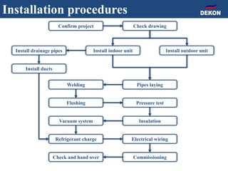
The document provides detailed installation instructions for DC inverter VRF systems, covering procedures for indoor and outdoor unit installation, piping, electrical wiring, and drainage systems. Key steps include proper placement for maintenance, ensuring gas-tightness, and setting up electrical wiring in compliance with regulations. The document emphasizes careful practices in each stage to prevent future issues and enhance system performance.

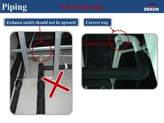
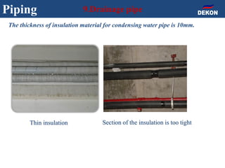
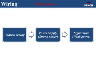
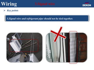
![Wiring 1.Address setting
Indoor address setting by Remote controller
Indoor unit address
NO.
Methold
Press [Sleep] button 8 times within 5
seconds to enter into the interface of
remote parameter change;
Select “parameter NO.” as “1” to enter
the indoor unit addressing mode;
set “Indoor unit address NO.” as
required on site;
press “sending button” to send order;
When hearing buzzer once, it indicates
successful setting](https://image.slidesharecdn.com/dcinvertervrfinstallationinstruction-170819022834/85/Dc-inverter-vrf-installation-instructions-and-Tips-66-320.jpg)