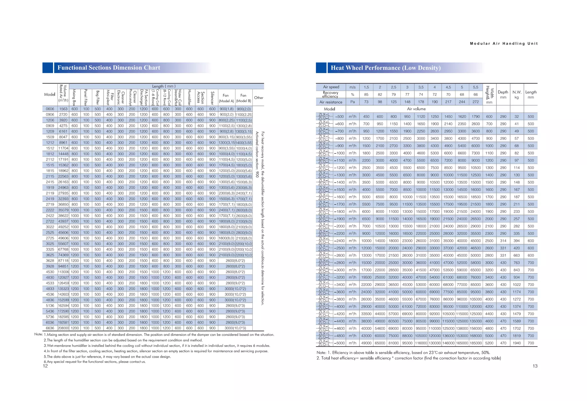
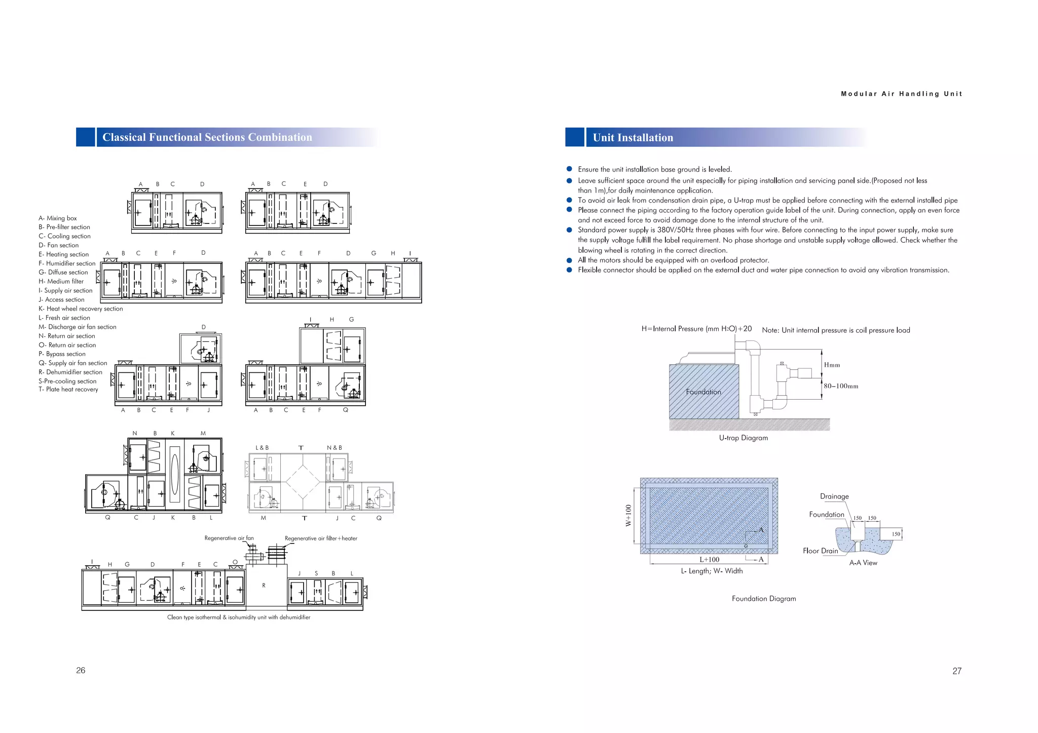
3
k
k
k
panel
Interior
Insulate
Profile
Nut
Bots &
Tenon 2
High density
Sealing
Exterior
panel
rubber
nuts
Profile foam
ring
Tenon 1
Pillar
Pillar
reduction. Vice versa, spraying can also apply for air enthalpy increase,
Silencer
Professional Selection Software
Easy Installation
k
Total
Heating
Capacity
Total
Heating
Capacity
Total
Heating
Capacity
Total
Heating
Capacity
Total
Heating
Capacity
Total
Heating
Capacity
Total
Heating
Capacity
Total
Heating
Capacity
Condensing
drainpipe
diameter(DN)
Steam&Hot
RatedAir
Volume
MixingBox
PanelFilter
BagFilter
Mini-pleat
Photocatalyst
Discharge/
CoolingCoil
Humidifier
Access
Silencer
Fan
(Model A)
Fan
(Model B)
Other
Filter
Electronic
Cleaner
Cleaner
FASection
(1-6Rows)
CoolingCoil
(8-12Rows)
WaterCoil
Section
Forheatrecoverymodel,thedehumidifiersectionlengthbasedontheactualconditiontodetermineforselection.
Activatedcarbonsection:900
Note: 1.Mixing section and supply air section is of standard dimension. The position and dimension of the damper can be considered based on the situation.
2.The length of the humidifier section can be adjusted based on the requirement condition and method.
3.Wet-membrane humidifier is installed behind the cooling coil without individual section, if it is installed in individual section, it requires 6 modules.
5.The data above is just for reference, it may vary based on the actual case design.
6.Any special request for the functional sections, please contact Uus.
Width
Height&
4.In front of the filter section, cooling section, heating section, silencer section an empty section is required for maintenance and servicing purpose.
Width
Height&
Width
Height&
MixingBox
PanelFilter
BagFilter
Electronic
Cleaner
Photocatalyst
Cleaner
Waterbaffle
Silencer
Wet-membrane humidifier
sheet
(dry condition)
Thick Thick Thick Thick
Row Rows Rows Rows Rows Rows Rows Rows Rows
A- Mixing box
B- Pre-filter section
C- Cooling section
D- Fan section
E- Heating section
F- Humidifier section
G- Diffuse section
H- Medium filter
I- Supply air section
J- Access section
K- Heat wheel recovery section
M- Discharge air fan section
N- Return air section
O- Return air section
P- Bypass section
Q- Supply air fan section
R- Dehumidifier section
S-Pre-cooling section
L- Fresh air section
T- Plate heat recovery
Ü·®»½¬´§ ͬ¿®¬ ˰ øÓ±¬±® б©»® ïïµÉ÷
ͬ¿® Ü»´¬¿ ͬ¿®¬·²¹ øÓ±¬±® б©»® ïëµÉ÷
Û´»½¬®·½¿´ Ø»¿¬»® É·®·²¹
SB2- Start Button; KA-Intermediate Relay; KM1-Fan Motor Contactor; KM2-Electrical Heater Contactor
TH-Electrical Heater Protector; FH-Fire proof valve; KT1- On Delay Timer Relay; KT2- Off Delay Timer Relay
QF-Low Voltage Circuit Breaker; SA-Modes Switch (Open-Fan; Close-heater)
Ü«®·²¹ °±©»® ±²ô ¬¸» Ѳ ¼»´¿§ ¬·³»® ®»´¿§ -»¬ ¿- ³·²·³«³ íð -»½±²¼-ô »´-» ¬¸» Ѻº ¼»´¿§ ¬·³»® -»¬ ¿- ³·²·³«³
ïèð -»½±²¼-ò
É¿®²·²¹æ
²± ½·®½«·¬ ·- ¿´´±©»¼ò ߺ¬»® º¿² ³±¬±® ±°»®¿¬·²¹ ²±®³¿´´§ô ¬¸»² ¬¸» »´»½¬®·½¿´ ¸»¿¬»® ©·´´ ¾» ¿½¬·ª¿¬»¼ò ɸ»² ¬¸» «²·¬ -¬±°-ô
»´»½¬®·½¿´ ¸»¿¬»® ½«¬ ±ºº º·®-¬ º±® í ³·²«¬»-ô ¬¸»² ¬¸» ¾´±©»® ³±¬±® ©·´´ -¬±°ò
Û´»½¬®·½¿´ ¸»¿¬»® ¬¸»®³±-¬¿¬ ³«-¬ ½±²²»½¬ ©·¬¸ ¬¸» ¾´±©»® ³±¬±® ¿²¼ »´»½¬®·½¿´ ¸»¿¬»® ·²¬»®´±½µ·²¹ ½±²¬®±´ ½·®½«·¬ô
In the control design, the humidifier and other components' wiring diagram will refer to unit wiring diagram. Take attention for:
Humidifier and other components must interlock with fan motor. When the motor starts, then the humidifier can be activated;
else after cut off the humidifier then can stop the fan motor;

Dekon Modular ahu