HARDNESS, FRACTURE TOUGHNESS AND STRENGTH OF CERAMICS
07 seq logicii-ix2
1. CS 150 - Fall 2005 – Lec #7: Sequential Implementation – 1
Sequential Logic Implementation
Models for representing sequential circuits
Abstraction of sequential elements
Finite state machines and their state diagrams
Inputs/outputs
Mealy, Moore, and synchronous Mealy machines
Finite state machine design procedure
Verilog specification
Deriving state diagram
Deriving state transition table
Determining next state and output functions
Implementing combinational logic
CS 150 - Fall 2005 – Lec #7: Sequential Implementation – 2
react right away to leaving the wall
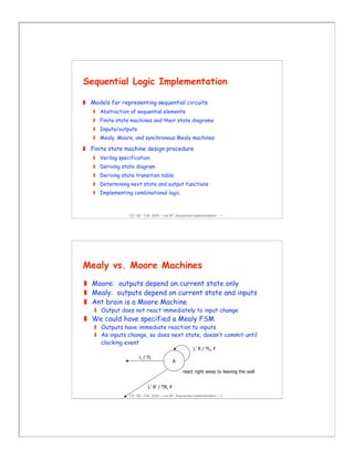
Mealy vs. Moore Machines
Moore: outputs depend on current state only
Mealy: outputs depend on current state and inputs
Ant brain is a Moore Machine
Output does not react immediately to input change
We could have specified a Mealy FSM
Outputs have immediate reaction to inputs
As inputs change, so does next state, doesn’t commit until
clocking event
A
L’ R’ / TR, F
L / TL
L’ R / TL, F
2. CS 150 - Fall 2005 – Lec #7: Sequential Implementation – 3
D/1
E/1
B/0
A/0
C/0
1
0
0
0
0
1
1
1
1
0
reset
current next
reset input state state output
1 – – A
0 0 A B 0
0 1 A C 0
0 0 B B 0
0 1 B D 0
0 0 C E 0
0 1 C C 0
0 0 D E 1
0 1 D C 1
0 0 E B 1
0 1 E D 1
Specifying Outputs for a Moore Machine
Output is only function of state
Specify in state bubble in state diagram
Example: sequence detector for 01 or 10
CS 150 - Fall 2005 – Lec #7: Sequential Implementation – 4
current next
reset input state state output
1 – – A 0
0 0 A B 0
0 1 A C 0
0 0 B B 0
0 1 B C 1
0 0 C B 1
0 1 C C 0
B
A
C
0/1
0/0
0/0
1/1
1/0
1/0
reset/0
Specifying Outputs for a Mealy
Machine
Output is function of state and inputs
Specify output on transition arc between states
Example: sequence detector for 01 or 10
3. CS 150 - Fall 2005 – Lec #7: Sequential Implementation – 5
state feedback
inputs
outputsreg
Combinational
logic
for
Next State
Logic
for
outputs
inputs outputs
state feedback
regCombinational
logic for
Next State
Logic
for
outputs
Comparison of Mealy and Moore Machines
Mealy Machines tend to have less states
Different outputs on arcs (n^2) rather than states (n)
Moore Machines are safer to use
Outputs change at clock edge (always one cycle later)
In Mealy machines, input change can cause output change as soon as
logic is done – a big problem when two machines are interconnected –
asynchronous feedback
Mealy Machines react faster to inputs
React in same cycle – don't need to wait for clock
In Moore machines, more logic may be necessary to decode state
into outputs – more gate delays after
CS 150 - Fall 2005 – Lec #7: Sequential Implementation – 6
D Q
Q
B
A
clock
out
D Q
Q
D Q
Q
clock
out
A
B
Mealy and Moore Examples
Recognize A,B = 0,1
Mealy or Moore?
4. CS 150 - Fall 2005 – Lec #7: Sequential Implementation – 7
D Q
Q
D Q
Q
D Q
Q
D Q
Q
A
B
clock
out
D Q
Q
D Q
Q
A
B
clock
out
Mealy and Moore Examples (cont’d)
Recognize A,B = 1,0 then 0,1
Mealy or Moore?
CS 150 - Fall 2005 – Lec #7: Sequential Implementation – 8
Registered Mealy Machine (Really Moore)
Synchronous (or registered) Mealy Machine
Registered state AND outputs
Avoids ‘glitchy’ outputs
Easy to implement in programmable logic
Moore Machine with no output decoding
Outputs computed on transition to next state rather than
after entering
View outputs as expanded state vector
Inputs
Outputs
Current State
output
logic
next state
logic
5. CS 150 - Fall 2005 – Lec #7: Sequential Implementation – 9
// State assignment
parameter zero = 0, one1 = 1, two1s = 2;
module reduce (out, clk, reset, in);
output out;
input clk, reset, in;
reg out;
reg [1:0] state; // state register
reg [1:0] next_state;
Verilog FSM - Reduce 1s Example
Change the first 1 to 0 in each string of 1’s
Example Moore machine implementation
1
0
0
0
1
1
zero
[0]
one1
[0]
two1s
[1]
CS 150 - Fall 2005 – Lec #7: Sequential Implementation – 10
always @(in or state)
case (state)
zero: begin // last input was a zero
out = 0;
if (in) next_state = one1;
else next_state = zero;
end
one1: begin // we've seen one 1
out = 0;
if (in) next_state = two1s;
else next_state = zero;
end
two1s: begin // we've seen at least 2 ones
out = 1;
if (in) next_state = two1s;
else next_state = zero;
end
default: begin // in case we reach a bad state
out = 0;
next_state = zero;
endcase
include all signals
that are input to state
and output equations
Moore Verilog FSM (cont’d)
1
0
0
0
1
1
zero
[0]
one1
[0]
two1s
[1]
6. CS 150 - Fall 2005 – Lec #7: Sequential Implementation – 11
// Implement the state register
always @(posedge clk)
if (reset) state <= zero;
else state <= next_state;
endmodule
Moore Verilog FSM (cont’d)
1
0
0
0
1
1
zero
[0]
one1
[0]
two1s
[1]
CS 150 - Fall 2005 – Lec #7: Sequential Implementation – 12
7
module reduce (clk, reset, in, out);
input clk, reset, in; output out;
reg out; reg state; // state register
reg next_state;
parameter zero = 0, one = 1;
always @(in or state)
case (state)
zero: begin // last input was a zero
if (in) next_state = one;
else next_state = zero;
out = 0;
end
one: // we've seen one 1
if (in) begin
next_state = one;
out = 1;
end
else begin
next_state = zero;
out = 0;
end
endcase
always @(posedge clk)
if (reset) state <= zero;
else state <= next_state;
endmodule
Mealy Verilog FSM for Reduce-1s Example
1/00/0
0/0
1/1
zero
one1
7. CS 150 - Fall 2005 – Lec #7: Sequential Implementation – 13
7
module reduce (clk, reset, in, out);
input clk, reset, in; output out;
reg out; reg state; // state register
reg next_state; reg next_out;
parameter zero = 0, one = 1;
always @(in or state)
case (state)
zero: begin // last input was a zero
if (in) next_state = one;
else next_state = zero;
next_out = 0;
end
one: // we've seen one 1
if (in) begin
next_state = one;
next_out = 1;
end
else begin
next_state = zero;
next_out = 0;
end
endcase
always @(posedge clk)
if (reset) begin
state <= zero; out <= 0;
end
else begin
state <= next_state; out <= next_out;
end
endmodule
Synchronous Mealy Verilog FSM for
Reduce-1s Example
1/00/0
0/0
1/1
zero
one1
CS 150 - Fall 2005 – Lec #7: Sequential Implementation – 14
Announcements
Review Session, Today, 5-6 PM, 125 Cory Hall
Examination, Wednesday, 1-2:30 PM, 125 Cory Hall
Five Quiz-like Questions -- Please Read Them Carefully! They
are not intended to be tricky; they should contain all the
information you need to answer the question correctly
No calculators or other gadgets are necessary! Don’t bring
them! No blue books! All work on the sheets handed out!
Do bring pencil and eraser please! If you like to unstaple the
exam pages, then bring a stapler with you! Write your name
and student ID on EVERY page in case they get separated --
it has happened!
Don’t forget your two-sided 8.5” x 11” crib sheet!
8. CS 150 - Fall 2005 – Lec #7: Sequential Implementation – 15
Announcements
Examination, Wednesday, 1-2:30 PM, 125 Cory Hall
Topics covered through last Wednesday
Combinational logic: design and optimization (K-maps up to and including 6
variables)
Implementation: Simple gates (minimum wires and gates), PLA structures
(minimum unique terms), Muxes, Decoders, ROMs, (Simplified) Xilinx CLB
Sequential logic: R-S latches, flip-flops, transparent vs. edge-triggered
behavior, master/slave concept
Basic Finite State Machines: Representations (state diagrams, transition
tables), Moore vs. Mealy Machines, Shifters, Registers, Counters
Structural and Behavioral Verilog for combinational and sequential logic
Labs 1, 2, 3
K&B: Chapters 1, 2 (2.1-2.5), 3 (3.1, 3.6), 4 (4.1, 4.2, 4.3), 6 (6.1, 6.2.1,
6.3), 7 (7.1, 7.2, 7.3)
CS 150 - Fall 2005 – Lec #7: Sequential Implementation – 16
Vending
Machine
FSM
N
D
Reset
Clock
OpenCoin
Sensor
Release
Mechanism
Example: Vending Machine
Release item after 15 cents are deposited
Single coin slot for dimes, nickels
No change
9. CS 150 - Fall 2005 – Lec #7: Sequential Implementation – 17
Example: Vending Machine (cont’d)
Suitable Abstract Representation
Tabulate typical input sequences:
3 nickels
nickel, dime
dime, nickel
two dimes
Draw state diagram:
Inputs: N, D, reset
Output: open chute
Assumptions:
Assume N and D asserted
for one cycle
Each state has a self loop
for N = D = 0 (no coin)
S0
Reset
S2
D
S6
[open]
D
S4
[open]
D
S1
N
S3
N
S7
[open]
N
S5
[open]
N
CS 150 - Fall 2005 – Lec #7: Sequential Implementation – 18
Example: Vending Machine (cont’d)
Minimize number of states - reuse states whenever possible
symbolic state table
present inputs next output
state D N state open
0¢ 0 0 0¢ 0
0 1 5¢ 0
1 0 10¢ 0
1 1 – –
5¢ 0 0 5¢ 0
0 1 10¢ 0
1 0 15¢ 0
1 1 – –
10¢ 0 0 10¢ 0
0 1 15¢ 0
1 0 15¢ 0
1 1 – –
15¢ – – 15¢ 1
0¢
Reset
5¢
N
N
N + D
10¢
D
15¢
[open]
D
10. CS 150 - Fall 2005 – Lec #7: Sequential Implementation – 19
present state inputs next state output
Q1 Q0 D N D1 D0 open
0 0 0 0 0 0 0
0 1 0 1 0
1 0 1 0 0
1 1 – – –
0 1 0 0 0 1 0
0 1 1 0 0
1 0 1 1 0
1 1 – – –
1 0 0 0 1 0 0
0 1 1 1 0
1 0 1 1 0
1 1 – – –
1 1 – – 1 1 1
Example: Vending Machine (cont’d)
Uniquely Encode States
CS 150 - Fall 2005 – Lec #7: Sequential Implementation – 20
D1 = Q1 + D + Q0 N
D0 = Q0’ N + Q0 N’ + Q1 N + Q1 D
OPEN = Q1 Q0
Example: Vending Machine (cont’d)
Mapping to Logic
0 0 1 1
0 1 1 1
X X X X
1 1 1 1
Q1D1
Q0
N
D
0 1 1 0
1 0 1 1
X X X X
0 1 1 1
Q1D0
Q0
N
D
0 0 1 0
0 0 1 0
X X X X
0 0 1 0
Q1Open
Q0
N
D
12. CS 150 - Fall 2005 – Lec #7: Sequential Implementation – 23
7
module vending (open, Clk, Reset, N, D);
input Clk, Reset, N, D; output open;
reg open; reg state; // state register
reg next_state;
parameter zero = 0, five = 1, ten = 2, fifteen = 3;
always @(N or D or state)
case (state)
zero: begin
if (D) next_state = five;
else if (N) next_state = ten;
else next_state = zero;
open = 0;
end
…
fifteen: begin
if (!Reset) next_state = fifteen;
else next_state = zero;
open = 1;
end
endcase
always @(posedge clk)
if (Reset || (!N && !D)) state <= zero;
else state <= next_state;
endmodule
Moore Verilog FSM for Vending Machine
0¢
[0]
10¢
[0]
5¢
[0]
15¢
[1]
N’ D’ + Reset
D
D
N
N+D
N
N’ D’
Reset’
N’ D’
N’ D’
Reset
CS 150 - Fall 2005 – Lec #7: Sequential Implementation – 24
7
module vending (open, Clk, Reset, N, D);
input Clk, Reset, N, D; output open;
reg open; reg state; // state register
reg next_state; reg next_open;
parameter zero = 0, five = 1, ten = 2, fifteen = 3;
always @(N or D or state)
case (state)
zero: begin
if (D) begin
next_state = ten; next_open = 0;
end
else if (N) begin
next_state = five; next_open = 0;
end
else begin
next_state = zero; next_open = 0;
end
end
…
endcase
always @(posedge clk)
if (Reset || (!N && !D)) begin state <= zero; open <= 0; end
else begin state <= next_state; open <= next_open; end
endmodule
Mealy Verilog FSM for Vending Machine
0¢
10¢
5¢
15¢
(N’ D’ + Reset)/0
D/0
D/1
N/0
N+D/1
N/0
N’ D’/0
Reset’/1
N’ D’/0
N’ D’/0
Reset/0
13. CS 150 - Fall 2005 – Lec #7: Sequential Implementation – 25
Example: Traffic Light Controller
A busy highway is intersected by a little used farmroad
Detectors C sense the presence of cars waiting on the farmroad
with no car on farmroad, light remain green in highway direction
if vehicle on farmroad, highway lights go from Green to Yellow to Red,
allowing the farmroad lights to become green
these stay green only as long as a farmroad car is detected but never
longer than a set interval
when these are met, farm lights transition from Green to Yellow to
Red, allowing highway to return to green
even if farmroad vehicles are waiting, highway gets at least a set
interval as green
Assume you have an interval timer that generates:
a short time pulse (TS) and
a long time pulse (TL),
in response to a set (ST) signal.
TS is to be used for timing yellow lights and TL for green lights
CS 150 - Fall 2005 – Lec #7: Sequential Implementation – 26
highway
farm road
car sensors
Example: Traffic Light Controller
(cont’d)
Highway/farm road intersection
14. CS 150 - Fall 2005 – Lec #7: Sequential Implementation – 27
Example: Traffic Light Controller
(cont’d)
Tabulation of Inputs and Outputs
inputs description outputs description
reset place FSM in initial state HG, HY, HR assert green/yellow/red highway lights
C detect vehicle on the farm road FG, FY, FR assert green/yellow/red highway lights
TS short time interval expired ST start timing a short or long interval
TL long time interval expired
Tabulation of unique states – some light configurations
imply others
state description
S0 highway green (farm road red)
S1 highway yellow (farm road red)
S2 farm road green (highway red)
S3 farm road yellow (highway red)
CS 150 - Fall 2005 – Lec #7: Sequential Implementation – 28
S0: HG
S1: HY
S2: FG
S3: FY
Example: Traffic Light Controller
(cont’d)
State Diagram Reset
TS'
TS / ST
(TL•C)'
TL•C / ST
TS'
TS / ST
(TL+C')'
TL+C' / ST
S0
S2
S3S1
TL+C / ST
15. CS 150 - Fall 2005 – Lec #7: Sequential Implementation – 29
Inputs Present State Next State Outputs
C TL TS ST H F
0 – – HG HG 0 Green Red
– 0 – HG HG 0 Green Red
1 1 – HG HY 1 Green Red
– – 0 HY HY 0 Yellow Red
– – 1 HY FG 1 Yellow Red
1 0 – FG FG 0 Red Green
0 – – FG FY 1 Red Green
– 1 – FG FY 1 Red Green
– – 0 FY FY 0 Red Yellow
– – 1 FY HG 1 Red Yellow
SA1: HG = 00 HY = 01 FG = 11 FY = 10
SA2: HG = 00 HY = 10 FG = 01 FY = 11
SA3: HG = 0001 HY = 0010 FG = 0100 FY = 1000 (one-hot)
output encoding – similar problem
to state assignment
(Green = 00, Yellow = 01, Red = 10)
Example: Traffic Light Controller
(cont’d)
Generate state table with symbolic states
Consider state assignments
CS 150 - Fall 2005 – Lec #7: Sequential Implementation – 30
Traffic Light Controller Verilog
module traffic (ST, Clk, Reset, C, TL, TS);
input Clk, Reset, C, TL, TS; output ST;
reg ST; reg state;
reg next_state; reg next_ST;
parameter S0 = 0, S1 = 1, S2 = 2, S3 = 3;
always @(C or TL or TS or state)
case (state)
S0: if (!(TL && C)) begin
next_state = S0; next_ST = 0;
else if (TL || C) begin
next_state = S1; next_ST = 1;
end
…
endcase
always @(posedge Clk)
if (Reset) begin state <= S0; ST <= 0; end
else begin state <= next_state; ST <= next_ST; end
endmodule
Reset
TS'
TS / ST
(TL•C)'
TL•C
TS'
TS / ST
(TL+C')'
TL+C' / ST
S0
S2
S3S1
TL+C / ST
17. CS 150 - Fall 2005 – Lec #7: Sequential Implementation – 33
Vending Machine (cont’d)
OPEN = Q1Q0 creates a combinational delay after Q1 and Q0
change
This can be corrected by retiming, i.e., move flip-flops and logic
through each other to improve delay
OPEN = reset'(Q1 + D + Q0N)(Q0'N + Q0N' + Q1N + Q1D)
= reset'(Q1Q0N' + Q1N + Q1D + Q0'ND + Q0N'D)
Implementation now looks like a synchronous Mealy machine
Common for programmable devices to have FF at end of logic
CS 150 - Fall 2005 – Lec #7: Sequential Implementation – 34
OPEN = reset'(Q1Q0N' + Q1N + Q1D + Q0'ND + Q0N'D)
Vending Machine (Retimed PLD
Mapping)
OPEN
DQ
DQ
DQ
Q0
Q1
Open
Seq
Seq
Seq
CLK
N
D
Reset
18. CS 150 - Fall 2005 – Lec #7: Sequential Implementation – 35
Sequential Logic Implementation
Summary
Models for representing sequential circuits
Abstraction of sequential elements
Finite state machines and their state diagrams
Inputs/outputs
Mealy, Moore, and synchronous Mealy machines
Finite state machine design procedure
Verilog specification
Deriving state diagram
Deriving state transition table
Determining next state and output functions
Implementing combinational logic