Downloaded 8,329 times
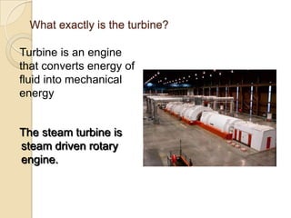
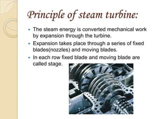
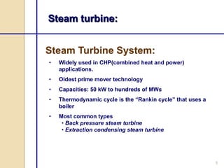
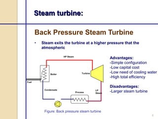
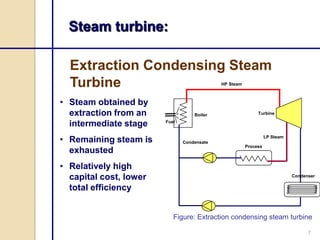
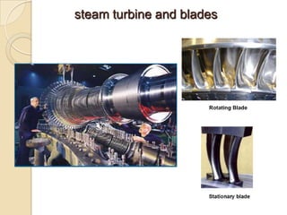
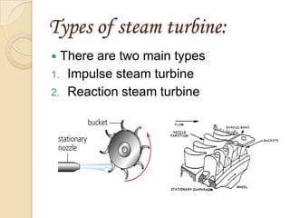
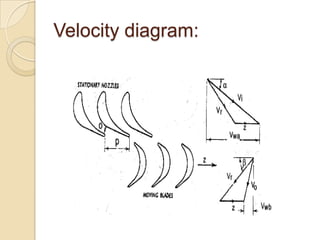
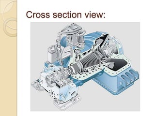
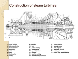
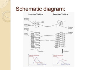
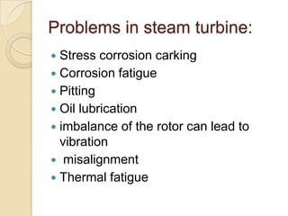
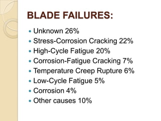
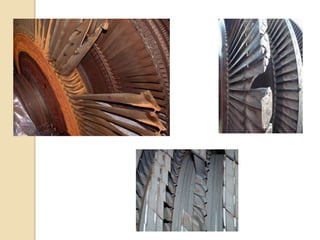


Steam turbines work by converting the energy of expanding steam into rotational motion. They have several key components and come in two main types: impulse and reaction. Impulse turbines use nozzles to direct high velocity steam onto turbine blades for impulse, while reaction turbines utilize both fixed and moving blades to expand steam. Common problems in steam turbines include stress corrosion cracking, corrosion fatigue, thermal fatigue, and pitting due to chemical attack from corrosive elements in the steam. Proper lubrication and preventing blade deterioration are important for optimizing steam turbine performance and lifespan.


![[PPT] on Steam Turbine](https://cdn.slidesharecdn.com/ss_thumbnails/spsharmafinalppt-140608082156-phpapp01-thumbnail.jpg?width=640&height=640&fit=bounds)


