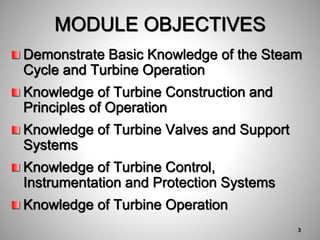
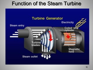
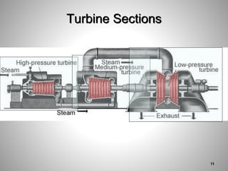
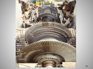
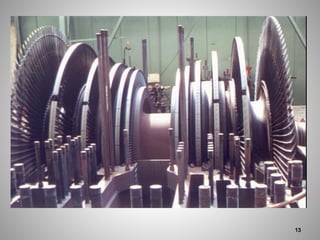
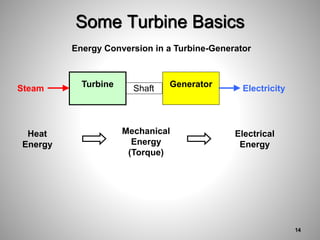
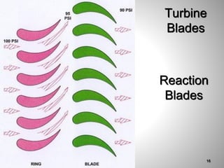
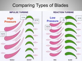
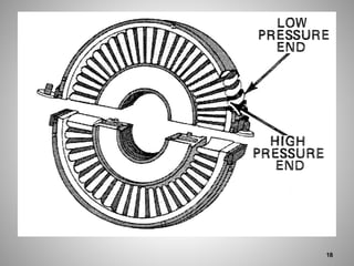
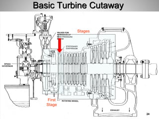
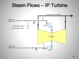
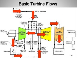
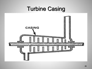
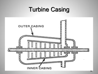
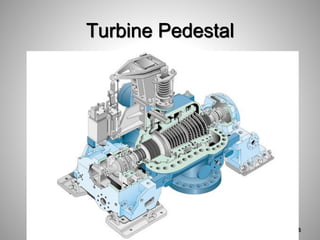
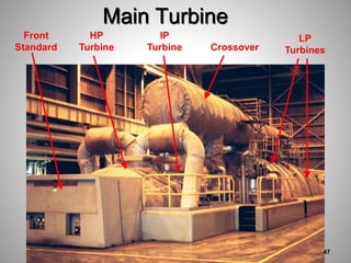
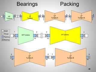
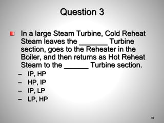
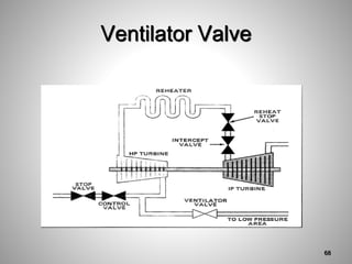
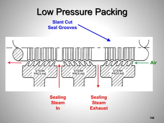
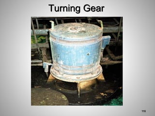
Power Plant Fundamentals
Training Program
Click to Start Program
Industrial Resources, Inc.
A Training Services Company
Power Plant Fundamentals
Training Program
Module 10 Turbines
INDUSTRIAL RESOURCES, INC.
© 2009 - Industrial Resources, Inc.
Demonstrate Basic Knowledge of the Steam
Cycle and Turbine Operation
Knowledge of Turbine Construction and
Principles of Operation
Knowledge of Turbine Valves and Support
Systems
Knowledge of Turbine Control,
Instrumentation and Protection Systems
Knowledge of Turbine Operation
MODULE OBJECTIVES
3
Steam Cycle and Turbine Operation
Review the purpose of the Steam Turbine
Look at general arrangement of Steam
Turbines
Look inside a Steam Turbine to see what
is happening to the Steam passing
through it
4
5
6
There are many accessories necessary for
commercial operation of a steam turbine
– Governing systems
– Bearing lubrication system
– Piping systems for steam supply and exhaust
– Steam condensing system are a few of the
auxiliary systems required
Turbine Principles of Operation
Accessories
7
Simple Impulse & Reaction
Turbines
8
Power Plant – Energy Converter
Boiler
Turbine
Generator
Fuel (Chemical
Energy)
Air
(Oxygen)
Steam (Thermal Energy)
Torque (Mechanical Energy)
9
Function of the Steam Turbine
10
Turbine Sections
11
12
13
Some Turbine Basics
Shaft
Turbine
Steam Generator Electricity
Mechanical
Energy
(Torque)
Heat
Energy
Electrical
Energy
Energy Conversion in a Turbine-Generator
14
Turbine
Blades
Impulse
Blades
15
Turbine
Blades
Reaction
Blades
16
Comparing Types of Blades
High
Pressure
Low
Pressure
17
18
19
Steam
Turbine
Stage
20
Shell and Stationary Blades
21
Disk Type Rotor
22
Drum Type Rotor
23
Basic Turbine Cutaway
First
Stage
Stages
24
Question 1
What is the purpose of the Steam
Turbine?
– Convert mechanical energy into thermal
energy
– Convert thermal energy into mechanical
energy
– Convert electrical energy into mechanical
energy
– Act as a heat sink for the Boiler
25
Question 1 Answer
If you said convert thermal energy into
mechanical energy, you were right. We
want to change the heat in steam into
torque on the shaft connected to the
Generator.
26
Question 2
In a Steam Turbine, a set of Fixed
Blades followed by a set of Rotating
Blades is called a _____________.
– turbine
– rotor
– stage
– steam chest
27
Question 2 Answer
If you said stage, you were right.
28
Turbine Construction
Have a basic idea of how a simple turbine
works
But want to look at a more complicated,
and common, turbine
Steam passes through stages, dropping in
pressure and expanding
Steam gives up thermal energy
Will look at one made up of several simple
turbines.
29
Multistage turbines use both impulse and
reaction blading to provide the most
efficient means of energy conversion
Turbine classifications
– Pressure velocity compounded
– Impulse reaction
– Straight reaction staging, are terms describing
ways in which manufacturers incorporate the
principles of blade design.
Multistage Turbines
30
Single Flow Turbine
31
Double Flow Turbine
32
All turbines may also be classified as
either single casing or compound
As the name implies, a single casing type
has only a single steam path from throttle
to exhaust
The term compound signifies a
construction in which the steam leaves the
high pressure casing before expansion is
complete and then goes through one or
more low pressure casings
Compound Turbine
33
LP Turbine
A
IP Turbine
HP Turbine
LP Turbine
B
Tandem Compound Turbine
34
Cross-Compound Turbine
35
Extraction Turbine
36
Extraction Steam System
37
Extraction Non-return Valve
38
Reheat turbines have been provided to
meet the demand for greater economy in
the operation of a modern power plant
In the reheat turbine
– High pressure steam is expanded through the
highest pressure section
– Then withdrawn and returned to the reheat
section of the boiler to increase its energy
level before expansion through the lower
pressure sections of the turbine
Reheat Turbine
39
Steam Flows – HP Turbine
Main
Steam SV-1 SV-2 SV-3
Warm-Up Line
Condenser
Drains Flash Tank
T
T P
P
Sample
CV Chest
HP Turbine
P
T
To Steam Air
Heaters
To Reheater
T P
To Soot
Blowers
To Reheater
40
Steam Flows – IP Turbine
IP Turbine
CRV-1
South Hot
Reheat Line
T
Main Stop Leakoff
From Ventilator Valve
CRV-2
North Hot
Reheat Line
T
Crossover to LP Turbines
41
Basic Turbine Flows
42
Turbine Casing
43
Turbine Casing
44
Sliding Pedestal
45
Turbine Pedestal
46
Main Turbine
Front
Standard
HP
Turbine
IP
Turbine
LP
Turbines
Crossover
47
Bearings
Shaft
Packing
Bearing
Thrust
1
N
1
N
2
2
HP
Turbine
3
N
3
IP
Turbine N
4
4
N
5
LP
Turbine A N
6
6
5
N
7
LP
Turbine B N
8
8
7
1
N1 N2
2
HP Turbine
3
N3
IP Turbine
N4
4
N5
LP
Turbine A
N6
6
5
N7
LP
Turbine B
N8
8
7
Packing
48
Question 3
In a large Steam Turbine, Cold Reheat
Steam leaves the _______ Turbine
section, goes to the Reheater in the
Boiler, and then returns as Hot Reheat
Steam to the ______ Turbine section.
– IP, HP
– HP, IP
– IP, LP
– LP, HP
49
Question 3 Answer
If you said HP, IP, you were right.
50
Question 4
In a large Steam Turbine, Crossover
Steam is the steam that leaves the
_____ Turbine section and goes to the
_____ Turbine section.
– IP, HP
– HP, IP
– IP, LP
– LP, HP
51
Question 4 Answer
If you said IP, LP, you were right.
52
Turbine Valves
Main Control Valves
Main Stop Valves
Combined Reheat Stop Valves (CRVs)
Turbine Drains
Valve Drains
Blowdown Valve
Ventilator Valve
53
Control Valve
Steam
Inlet
Poppet
Valves
Poppet Valve
Stems
First Stage
Diaphragm
54
Full & Partial Arc Admission
55
Control Valves
56
Control Valves
57
Main Stop
Valve
Valve Body
Above Seat Drain
Below Seat Drain
Hydraulic Operator
Stem Leak-Off
58
Main Stop Valve Bypass
59
Combined
RH Stop &
Intercept
Valves
Intercept
Disc
Reheat
Stop
Disc
Steam In
Steam
Out
60
CRVs Operating
Linkage
Valve
Stem
Valve
Body
61
Turbine Drain Valves
Main Steam Leads – manual
Turbine Bypass Valves – pneumatic
Stop Valves Before Seat – MOVs
Stop Valves After Seat – MOVs
Cold Reheat – manual
CRVs Before Seat – manual
CRVs After Seat – manual
Extraction Lines - manual
62
Turbine Drain Valves
63
Operating Turbine Drains
64
Stop
Valve
Drains
SV-2 After
Seat Drain
SV-2
Before
Seat Drain
SV-1
Before
Seat Drain
SV-1 After
Seat Drain
65
Blowdown Valve
Releases Steam from N2 Packing on Turbine
Goes to Condenser
Ventilator Valve
Releases Steam from Extraction Line on HP Turbine
Protects last few stages from windage on load rejection
Goes to Condenser
66
Blowdown Valve
67
Ventilator Valve
68
Question 5
Which Turbine Valve acts as a stop valve
for Hot Reheat Steam going to the IP
Turbine?
– Main Stop Valve
– Main Control Valve
– Combined Reheat Valve (CRV)
– Main Poppet Valve
69
Question 5 Answer
If you said Combined Reheat Valve (CRV),
you were right.
70
Question 6
Which Turbine Valve controls the exact
flowrate of Main Steam to the HP
Turbine?
– Main Stop
– Main Control Valve
– Combined Reheat Valve (CRV)
– Above Seat Drain Valve
71
Question 6 Answer
If you said Main Control Valve, you were
right.
72
Turbine Support Systems
Turning Gear
Turbine Lube Oil System
– Turbine Oil Reservoir
– Turbine Oil Pumps
– Turbine Oil Conditioner
Turbine Steam Seal System
73
Clean lubricating oil at the proper
pressure, temperature and flow must be
provided at all times that the turbine-
generator shafts are rotating
Lubricating oil provides a necessary
cooling affect on the bearings, even when
the rotors are at rest
Because of the critical nature of a
continuous supply, back up AC and DC
pumps are provided for off-line or
emergency situations
Turbine Lube Oil System
74
The normal source for lube oil is the shaft
driven oil pump
A few units use a small turbine driven
pump as a backup
Cleanliness is very important in the lube oil
system
Contaminant's can affect lubricating
properties and foreign material can plug
lines or score bearing surfaces.
Turbine Lube Oil System (cont.)
75
Oil temperature is very important for
operation.
– Too low a temperature at speed will cause
vibration problems (oil whip)
– Too high a temperature will decrease the
viscosity and increase wear of bearing
surfaces
The lube oil also acts to cool the bearing
Turbine Lube Oil (cont.)
76
Main Oil Pumps
P
P
Main Oil
Pump
Booster
Pump (Pri.)
Bearing Oil
Header
Lube Oil
Coolers
P
Turning Gear
Oil Pump
Emergency Oil
Pump
Motor Suction
Pump
Oil Reservoir
L
LO Filter
Pump
LO
Cond.
77
78
Motor Suction Pump
P
P
Main Oil
Pump
Booster
Pump (Pri.)
Bearing Oil
Header
Lube Oil
Coolers
P
Turning Gear
Oil Pump
Emergency Oil
Pump
Motor Suction
Pump
Oil Reservoir
L
LO Filter
Pump
LO
Cond.
79
Emergency Bearing and Turning
Gear Oil Pumps
P
P
Main Oil
Pump
Booster
Pump (Pri.)
Bearing Oil
Header
Lube Oil
Coolers
P
Turning Gear
Oil Pump
Emergency Oil
Pump
Motor Suction
Pump
Oil Reservoir
L
LO Filter
Pump
LO
Cond.
80
81
Turbine Oil Coolers
P
P
Main Oil
Pump
Booster
Pump (Pri.)
Bearing Oil
Header
Lube Oil
Coolers
P
Turning Gear
Oil Pump
Emergency Oil
Pump
Motor Suction
Pump
Oil Reservoir
L
LO Filter
Pump
LO
Cond.
82
83
Turbine Oil Conditioner
P
P
Main Oil
Pump
Booster
Pump (Pri.)
Bearing Oil
Header
Lube Oil
Coolers
P
Turning Gear
Oil Pump
Emergency Oil
Pump
Motor Suction
Pump
Oil Reservoir
L
LO Filter
Pump
LO
Cond.
84
85
Lube Oil Vapor Extractor
86
GE Turbine Lube Oil System
87
Westinghouse Lube Oil System
88
Bearings
Rotation
Shaft
Bearing
Oil In
Oil Out
89
90
Journal and Thrust Bearings
91
Steam Seal
92
Steam Seal System
93
94
95
Labyrinth Steam Seal
96
97
98
99
Turbine Water Seal
100
Water Seal
101
102
Steam Seal
System
Turbine Packing
N5
N1 N2 N3 N4 N6 N7 N8
Main
Steam
Aux.
Steam
M
SSAFV
MOV
MOV7021
M
MOV
SSFV
M
To Heater
To Condenser A
Diverting Valve
M
SSUV
MOV
MSV Below
Seat Drains
CV Valve Stem
Leak-off
To/From BFPT
Gland Steam
Drains
F
Ventilator
Valve
Hot
Reheat
Blowdown
Valve
103
Steam to
Packing
Turbine Packing
N5
N1 N2 N3 N4 N6 N7 N8
Main
Steam
Aux.
Steam
M
SSAFV
MOV
MOV7021
M
MOV
SSFV
M
To Heater
To Condenser A
Diverting Valve
M
SSUV
MOV
MSV Below
Seat Drains
CV Valve Stem
Leak-off
To/From BFPT
Gland Steam
Drains
F
Ventilator
Valve
Hot
Reheat
Blowdown
Valve
104
Unloading and
Diverting
Valves
Turbine Packing
N5
N1 N2 N3 N4 N6 N7 N8
Main
Steam
Aux.
Steam
M
SSAFV
MOV7025
MOV7021
M
MOV7020
SSFV
M
To Heater 3B
To Condenser A
Diverting Valve
M
SSUV
MOV7
308
MSV Below
Seat Drains
CV Valve Stem
Leak-off
To/From BFPT
Gland Steam
Drains
F
Ventilator
Valve
Hot
Reheat
Blowdown
Valve
105
Packing Exhaust
Turbine
Packing
N1
Seal
Steam
N3
Seal
Steam
N2
Seal
Steam
Steam Air
Heater
Extraction Line
N4
Seal
Steam
N6
Seal
Steam
N5
Seal
Steam
N8
Seal
Steam
N7
Seal
Steam
From
BFPTs
Gland
Steam
Condenser
106
High Pressure Packing
Steam Seal
Lands
Steam Air
Steam
Packing
Sealing Steam
In During
Start Up &
Low Load,
Out at Load
Sealing
Steam
Exhaust
Steam
Packing
Steam
Packing
107
Low Pressure Packing
Slant Cut
Seal Grooves
Sealing
Steam
In
Sealing
Steam
Exhaust
Air
108
109
Turning Gear
110
111
112
Turning Gear Controls
113
Question 7
What component seals steam inside the HP
Turbine casing?
– Thrust bearing
– Journal bearings
– Packing glands
– Turning gear
114
Question 7 Answer
If you said packing glands, you were right.
They seal air out of the LP turbine.
115
Question 8
Why is the Turbine shaft rotated at slow
speed while it cools down?
– Prevent sagging of the shaft of the Turbine
– Prevent it from cooling down too rapidly
– Keep adequate flow of oil
– To reduce the steam flow to the turbine
116
Question 8 Answer
If you said prevent sagging of the shaft,
you were right.
117
Turbine Control & Instrumentation
Extraction Control
Speed Control
Instrumentation (Supervisory)
Electro-Hydraulic Control (EHC)
Turbine Protective System
Turbine Trips
118
Turbine Control Valve
119
Hydraulic Actuator
120
Pilot Valve and Actuator
121
Mechanical Governor
122
Mechanical Governor
123
Hydraulic Governor
124
Electro-Hydraulic Control
125
Electronic Governor
126
Speed Changer Assembly
127
Speed Changer Switch
128
Extracting Steam
Extraction
Control
Devices
Front Standard - Control
129
Turbine Protective System
Turbines, even though massive, can be
damaged rather easily. Several operating
parameters must be maintained to prevent
damage
When a turbine rotor is allowed to run at
overspeed conditions, there may be
enough speed to cause complete
destruction of the turbine
130
Turbine Protective System
1st Line of Protection
– Main Speed Governor
(GE, West.)
– Pre-Emergency Governor
(GE)
– Auxiliary Governor
(Westinghouse)
– Cut Out Pre-Emergency
Governor
(GE)
– HP Speed Governor
– RH Speed Governor
(ABB)
2nd Line of Protection
– Emergency Governor
(Mechanical)
(GE,West.,ABB)
– Backup Emergency
Governor (Electrical)
(GE, WEST, ABB)
131
Emergency
Governor
Centrifugal
Force
132
Emergency
Trip Device
133
134
Generator Motoring
Turbines drive generators which deliver power
to the system under normal operating
conditions
If the steam input to the turbine is less than the
power required to maintain the turbine at rated
speed while the generator is synchronized to
the system, the power required to maintain the
generator and turbine at synchronous speed
will come from the system
135
Generator Motoring (cont.)
Turbines have limits to their ability to
operate under motoring conditions
The last stages of the low pressure rotors
have very long blades which can be
overheated by reduced steam flow or
degraded back pressure
The increased density of the blade
environment will result in the overheating
of the blades and exhaust hood
136
Main Turbine Trips
137
Turbine Supervisory
Instrumentation
Local
EHC Panel
Front Standard
Control Room Bench Boards
Control Room Vertical Boards
DCS
138
EHC Panel
139
Load Set
Load Selector
Loading Rate Limit
Circuit Breaker
Emerg. Trip
System
Vacuum Trip
Mechanical Trip
Trip Reset
Load
140
Control Room Instruments &
Controls
Throttle
Pressure
Before Seat
(Narrow Range)
Throttle
Pressure
Before Seat
(Wide Range)
Throttle
Pressure
After Seat
First Stage
Pressure
141
142
143
Turbine Supervisory Instruments
(cont.)
Because the rotating parts of a turbine are
in close proximity to the stationary parts, it
is necessary to measure the expansion of
each and compare these measurements
to ensure that the parts do not touch.
The three measurements of importance
are shell expansion, rotor expansion, and
differential expansion.
144
Diff and Rotor Expansion Detectors
145
Relationship Between Rotor and
Shell Expansion
146
147
Eccentricity Measurement
148
Hot Turbine Rotor Bow
149
150
This section is about Turbine Vibration
Shaft Rider
151
Proximity Probe
152
153
154
155
Abrasion
Thrust Bearings
Thrust Bearings
156
Thrust Bearings
157
Thrust Bearing Wear Detector
158
Normal Thrust Bearing
159
Failed Thrust Bearing
160
8 psi
decreasing
GE Thrust Bearing Wear Detector
161
30 psi alarm
80 psi trip
Westinghouse Thrust Bearing
Wear Detector
162
Turbine Control - EHC
Hydraulic Power Unit
EHC Cabinets
EHC Operating Panel
Valve Operators
Emergency Trip System
163
EHC Power Unit
EHC Fluid Tank
Primary Pump Filter Pump
Instrumentation
Fluid Cooler
164
Valve Position
Warming Rate
Pre-Warming
Auxiliary Valves
Chest Pressure
Speed Set - RPM
Starting Rate
Trip
Servo Valve Current
Stop Valves Control Valves Comb. Reheat Valves
Test Valves Test Valves Test Valves
Mech. Trip Test
Master Trip
Solenoid Test
Load Limit Initial Pressure Limit
Alarms Trip Anticipator Load Limit Set
Limiting
Pressure
165
Load Set
Load Selector
Loading Rate Limit
Circuit Breaker
Emerg. Trip
System
Vacuum Trip
Mechanical Trip
Trip Reset
Load
166
Load Set
Load Selector
Loading Rate Limit
Circuit Breaker
Emerg. Trip
System
Vacuum Trip
Mechanical Trip
Trip Reset
Load
167
Causes of Turbine Trip
Thrust Bearing Wear
Low Hydraulic Pressure
Loss of Stator Cooling to Generator
Low Main Oil Pump Discharge Pressure
Loss of both BFPs
Loss of EHC pressure
Manual Trip
Loss of all speed signals
High Exhaust Hood temperature
Low vacuum in Condenser
Loss of Hydraulic Trip pressure
168
Master Trip Solenoid
Closes:
– Main Stop Valves
– Main Control Valves
– Combined Reheat Valves
– Extraction line trip Valves
Opens:
– Packing Blowdown Valve
– Ventilator Valve
169
Question 9
One purpose of extracting steam from a
Steam Turbine, other than removing
moisture, is to save _________.
– water
– heat
– pressure
– temperature
170
Question 9 Answer
If you said heat, you were right.
171
Question 10
Which of the following will likely be the first
indication of mechanical problems or
damage in a Steam Turbine?
– High exhaust hood temperature
– High vibration
– Speed slightly low
– Reheat Steam temperature high
172
Question 10 Answer
If you said high vibration, you were right.
173
Turbine Operation
Startup
Normal Operation
Shutdown
174
Starting and Loading Instructions (SALI)
175
Turbine Startup
Verify all necessary systems are operating
 Electrical Power System,
 Instrument Air System,
 Turbine Lube Oil System,
 Turbine Steam Seal System,
 Closed Cooling Water System,
 Hydrogen Seal Oil System,
 Generator Stator Cooling System,
 Circulating Water System,
 Auxiliary Boilers and CRASS,
 Condensate System,
 Feedwater System.
176
Verify that the following conditions exist:
At least one Circulating Water Pump is
operating with the other Pump in hot
standby,
Closed Cooling Water Header pressure is
at least 75 psig,
Condenser Hotwell level is at least 12
inches but less than 36 inches,
177
Condensate Pump discharge temperature
is less than 125 degrees Fahrenheit and
discharge pressure is greater than 75 psig,
Deaerator level is at least 5 feet but less
than 9 feet, with pressure greater than 75
psig.
Condenser vacuum has been established
of at least 25 inches of Hg,
Generators are full of hydrogen,
Turbine Gear Oil Pump is in operation,
Motor Suction Oil Pump is running,
178
Main Turbine is on Turning Gear for the
required amount of time,
EHC System is operating properly,
the Turbine Lube Oil Pump trip and the
EHC Fluid Pump has been tested,
Main Turbine is tripped,
Exhaust Hood Spray is ready for
operation,
Steam seals are established on the
Turbine,
179
 Vacuum has been drawn in the
Condensers,
 The Boiler Trip is reset,
 The Turbine Master Trip is reset,
 The EHC First Hit and the Generator-Main
Transformer Trip Relays are reset,
 All Turbine valves are in the proper position
for starting the Turbine.
 Position all Turbine drain valves for Turbine
start to make sure that no moisture in the
Turbine or Steam lines could damage the
Turbine blades.
180
Shaft Pre-Warming
Warming
Rate
Pre-Warming
Auxiliary Valves
Chest Pressure
Speed Set - RPM
Starting Rate
Trip
Valve Position
Servo Valve Current
Stop Valves Control Valves Comb. Reheat
Valves
Test Valves Test Valves Test Valves
Mech. Trip Test
Master Trip
Solenoid Test
Load Limit Initial Pressure
Limit
Alarms Trip Anticipator Load Limit Set
Limiting
Pressure
181
Preparing to Roll
182
Roll Up the Turbine
Warming
Rate
Pre-Warming
Auxiliary Valves
Chest Pressure
Speed Set - RPM
Starting Rate
Trip
Valve Position
Servo Valve Current
Stop Valves Control Valves Comb. Reheat
Valves
Test Valves Test Valves Test Valves
Mech. Trip Test
Master Trip
Solenoid Test
Load Limit Initial Pressure
Limit
Alarms Trip Anticipator Load Limit Set
Limiting
Pressure
183
Synchronize and Load
Load Set
Load Selector
Loading Rate Limit
Circuit Breaker
Emerg. Trip System
Vacuum Trip
Mechanical Trip
Trip Reset
Load
184
Normal Operation
185
Turbine Shutdown
Load Set
Load Selector
Loading Rate Limit
Circuit Breaker
Emerg. Trip System
Vacuum Trip
Mechanical Trip
Trip Reset
Load
186
Question 11
The main purpose of Turbine Starting and
Loading instructions is to reduce Turbine
stress and maintain the Turbine
___________.
– design
– warranty
– speed
– vibration
187
Question 11 Answer
If you said warranty, you were right.
188
Question 12
As a Steam Turbine is being started up, the
most important instrumentation to check as
speed increases is the _______________.
– pressure
– temperature
– vibration
– thrust
189
Question 12 Answer
If you said vibration, you were right.
190
191
This concludes this training
presentation.
If you have further questions
about Power Plant
Fundamentals, consult with
your supervisor or training
manager.

Steam Cycle and Turbine Operation_New_Module.pdf