
Recommended
More Related Content
What's hot
What's hot (20)
Similar to Cad cam
Similar to Cad cam (20)
Recently uploaded
Recently uploaded (20)
Cad cam
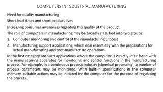
- 1. COMPUTERS IN INDUSTRIAL MANUFACTURING Need for quality manufacturing Short lead times and short product lives Increasing consumer awareness regarding the quality of the product The role of computers in manufacturing may be broadly classified into two groups: 1. Computer monitoring and control of the manufacturing process 2. Manufacturing support applications, which deal essentially with the preparations for actual manufacturing and post-manufacture operations In the first category are such applications where the computer is directly inter faced with the manufacturing apparatus for monitoring and control functions in the manufacturing process. For example, in a continuous process industry (chemical processing), a number of process parameters may be monitored. With built-in specifications in the computer memory, suitable actions may be initiated by the computer for the purpose of regulating the process.
- 2. In the second category, are all the support func tions that computers can pro vide for the successful com pletion of manufactur ing operations. The types of sup port that can be envisaged are the following: CAD— Computer Aided Design The use of computer methods to develop the geometric model of the product in three-dimensional form, such that the geometric and manufacturing requirements can be examined. CADD— Computer Aided Design and Drafting Combining the CAD function with drafting to generate the production drawings of the part for the purpose of downstream processing. CAE— Computer Aided Engineering The use of computer methods to support basic error checking, analysis, optimisation, manufacturability, etc., of a product design. CAM— Computer Aided Manufacturing Generally refers to the computer software used to develop the Computer Numerical Control part programs for machining and other processing applications. CAPP— Computer Aided Process Planning The use of computers to generate the process plans for the complete manufacture of products and parts. CATD— Computer Aided Tool Design Computer assistance to be used for developing the tools for manufacture such as jigs and fixtures, dies, and moulds. CAP— Computer Aided Planning The use of computers for many of the planning functions such as material requirement planning, computer aided scheduling, etc. CAQ— Computer Aided Quality Assurance The use of computers and computer-controlled equipment for assessing the inspection methods and developing the quality control and assurance functions. CAT— Computer Aided Testing Refers to the software tools that can take a system through its various phases of operations and examine the response against the expected results.
- 3. Product cycle (design and manufacturing
- 4. Product cycle revised with CAD/CAM overlaid.
- 5. Computer assistance for the design cycle
- 10. CAD • Layout design for the overall assembly • Individual component modelling • Assembly modelling • Interference and tolerance stack checking • Engineering drawings
- 13. CAM
- 16. CAD/CAM Systems Evaluation Criteria The various types of CAD/CAM systems are Mainframe-Based Systems, Minicomputer-Based Systems, Microcomputer-Based Systems and Workstation Based Systems. SYSTEM CONSIDERATIONS (i) Hardware Each workstation is connected to a central computer, called the server, which has enough large disk and memory to store users' files and applications programs as well as executing these programs. (ii) Software Three major contributing factors are the type of operating system the software runs under, the type of user interface and the quality of documentation. (iii) Maintenance Repair of hardware components and software updates comprise the majority of typical maintenance contracts. The annual cost of these contracts is substantial (about 5 to 10 percent of the initial system cost) and should be considered in deciding on the cost of a system in addition to the initial capital investment. (iv) Vendor Support and Service Vendor support typically includes training, field services and technical support. Most vendors provide training courses, sometimes on-site if necessary.
- 17. GEOMETRIC MODELING CAPABILITIES (i) Representation Techniques The geometric modeling module of a CAD/CAM system is its heart. The applications module of the system is directly related to and limited by the various representations it supports. Wireframes, surfaces and solids are the three types of modeling available. (ii) Coordinate Systems and Inputs In order to provide the designer with the proper flexibility to generate geometric models, various types of coordinate systems and coordinate inputs ought to be provided. Coordinate inputs can take the form of cartesian (x, y, z), cylindrical (r, θ, z) and spherical (θ, φ, z).
- 18. (iii) Modeling Entities The fact that a system supports a representation scheme is not enough. It is important to know the specific entities provided by the scheme. The ease to generate, verify and edit these entities should be considered during evaluation. (iv) Geometric Editing and Manipulation It is essential to ensure that these geometric functions exist for the three types of representations. Editing functions include intersection, trimming and projection and manipulations include translation, rotation, copy, mirror, offset, scaling and changing attributes. (v) Graphics Standards Support If geometric models' databases are to be transferred from one system to another, both systems must support exchange standards.
- 19. DESIGN DOCUMENTATION (i) Generation of Engineering Drawings After a geometric model is created, standard drafting practices are usually applied to it to generate the engineering drawings or the blueprints. Various views (usually top, front and right side) are generated in the proper drawing layout. Then dimensions are added, hidden lines are eliminated and/or dashed, tolerances are specified, general notes and labels are added, etc.
- 20. APPLICATIONS (i) Assemblies or Model Merging Generating assemblies and assembly drawings from individual parts is an essential process. (ii) Design Applications There are design packages available to perform applications such as mass property calculations, tolerance analysis, finite element modeling and analysis, injection modeling analysis and mechanism analysis and simulation. (iii) Manufacturing Applications The common packages available are tool path generation and verification, NC part programming, postprocessing, computer aided process planning, group technology, CIM applications and robot simulation. (iv) Programming Languages Supported It is vital to look into the various levels of programming languages a system supports. Attention should be paid to the syntax of graphics commands when they are used inside and outside the programming languages. If this syntax changes significantly between the two cases, user confusion and panic should be expected.
- 21. DATABASE STRUCTURES FOR GRAPHIC MODELLING Typical data that would normally be contained in a geometric model file is 1. Organisational data Identification number Drawing number Design origin and status of changes Current status Designer name Date of design Scale Type of projections Company 2. Technological data Geometry Dimensions Tolerances Surface finishes Material specifications or reference
- 22. In the case of geometric modelling, the database structure should provide some of the following functionalities: • Allow for greater interaction of the user with the modelling system. This should allow the user to add, delete and modify the data in the form of geometric entities as required during the process of modelling and other associated functions. • Support a large variety of types of data to be represented in the database as explained earlier. The types of data may be in the form of real and integer values, geometric information, textual information such as manufacturing notes or finishes, CNC tool paths, finite element meshes, etc. • The data structure should be able to allow for associating the data with the modelling process such that the design intent can be effectively captured by the data and can be utilised later for any of the modifications as required during the lifecycle of the product. • The data should allow for storing information in the most compact form possible such that less data storage and transmission speeds would be required for working in group environments. For example, multiple instances of geometry may only be stored once and then simply the instant information be used for manipulating that to generate the models or drawing as required. • Data should maintain complete associativity with all the downstream and upstream
- 23. Data Models A hierarchical representation of data for a product model A network representation of data for a product model A relational representation of data for a product model
- 24. Geometric Model Data Complete data structure for geometric models of products
- 25. Engineering data management within a manufacturing enterprise
- 26. COMPUTER GRAPHICS Model to be developed With WCS With WCS and UCS CO-ORDINATE SYSTEM
- 27. TRANSFORMATIONS The main types of pure transformations with which we are likely to come across are • Translation • Scaling • Reflection or mirror • Rotation
- 28. TRANSLATION. Translation involves moving the element from one location to another. ( x ' , y ' ) = (x,y) + T
- 29. SCALING. Scaling of an element is used to enlarge it or reduce its size. (x',y') = (x,y)S
- 30. Concatenation of Transformations It is the process to combine the individual transformations. care should be taken to see that the order of the matrix is same Homogeneous Representation The process of converting additive type of matrix to multiplicative
- 33. COLOUR RGB Model(Additive)-Used in displays CMY Model(Subtractive)-Used in printers
- 34. SHADING