Electricity and Electromagnetism (experimental study)
•
0 likes•95 views

You’ll understand the way to calculate and measure resistance in parallel and series circuits by knowing two of the three values of voltage, current, or resistance. In this experiment, there are 3 resistors, 1 power supply and wires you need for connecting resistors to each other, then to power supply. You can measure each resistor by an ohmmeter, voltages by voltmeter and currents by amperemeter (ammeter), while all of them can be measured by a multimeter. Use a multimeter for measuring resistance for better accuracy.

Recommended
More Related Content
What's hot
What's hot (20)
Similar to Electricity and Electromagnetism (experimental study)
Similar to Electricity and Electromagnetism (experimental study) (20)
More from Raboon Redar
More from Raboon Redar (17)
Recently uploaded
Recently uploaded (20)
Electricity and Electromagnetism (experimental study)
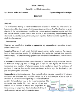
- 1. 1 Soran University Electricity and Electromagnetism By: Raboon Redar Muhammed Supervised by: Metin Sedighi 28/04/2019 ------------------------------------------------------------------------------------------------------------------ Abstract: You’ll understand the way to calculate and measure resistance in parallel and series circuits by knowing two of the three values of voltage, current, or resistance. You’ll realize that in series circuits, all the current values are equal but the voltage coming from power supply is divided into smaller amounts that the sum of them is equal to the total voltage. Opposite thing at the other hand, in parallel circuits, all the voltages are equal but the total current is equal to the sum of all the other currents. 1- Introduction: Materials are classified as insulators, conductors, or semiconductors according to their electric conductivity. Insulator: Materials through which electricity cannot pass are called insulators. The valence band of those materials remains full of electrons. The conduction band of those materials remains empty. The forbidden energy gap between the conduction band and the valence band is widest. Conductors: Valence band and the conduction band of conductors overlap each other. There is no forbidden energy gap here so energy gap is equal to zero (Eg=0). At absolute zero temperature large numbers of electrons remain in the conduction band. The resistance of conductor is very low, large number charge carriers are available here. So, the electricity can pass easily through the conductors. Semiconductors: Semiconductors are those materials whose electrical conductivity is between conductors and insulators. The forbidden energy gap of a semiconductor is nearly same as insulator. A semiconductor has partially full valence band and partially full conduction band at the room temperature. The conduction band remains fully empty and the valence band remains full of electrons at absolute zero temperature. So the increasing of temperature the electrical conductivity of semiconductors increase and resistance decreases.
- 2. 2 Different matters resist different amount of electricity, controlling the amount of electricity is important, so scientists have invented resistors of different types which have different amounts of resistance. Conductors allow current to flow through them easily, and charges do not lose much energy as they flow through these materials. Similar to how water gets slowed down when it encounters a smaller section in a pipe, electric current can encounter materials. This obstruction to flow is quantified by a variable called resistance and measured in ohms (Ω). If the resistances have one common point (nod), it’s called Series Resonance Circuit. If the resistances have two common points (nod), then it’s a Parallel Resonance Circuit. There are also complex circuits, which have both (series and parallel resistors) mixed in one circuit. Direct current (DC): In DC, the electrons always travel around the loop in the same direction (so the conventional current also has a constant direction). A direct current or electrons all move in one direction in a conductive wire. All battery-powered devices, like cell phones and flashlights, run on direct current. Note that a constant voltage will create a direct current. Alternating current (AC): In DC, electrons travel back and forth. A moment they all move collectively in one direction, and the next moment they all move collectively in the opposite direction, creating an oscillating electrical current. One back-and-forth oscillation is called a cycle, and the number of cycles delivered per time unit is called the frequency. Frequency is measured in hertz (Hz). One cycle per second is 1 Hz, ten cycles per second is 10 Hz, etc. Note that the voltage creating this current will alternate with the same frequency. (c) Resistors connected in parallel and series (a) Resistors connected in series (b) Resistors connected in parallel
- 3. 3 To understand the difference between AC and DC, you can also make a graph of electric current versus time. For direct current, the current is constant (a straight line). For alternating current, the current oscillates back and forth: Graphical representation of current (y-axis) versus time (x-axis) of direct current and alternating current. In this figure, the alternating current completes one cycle every second, i.e. it has a frequency of 1 Hz. Note that a negative current represents a current in the opposite direction. Power lines deliver alternating electric current to our homes. Depending on what country you are in, alternating current from power outlets is usually 50 or 60 cycles per second (Hz). Most electric appliances we "plug into the wall" run on alternating current. Some appliances need an "adapter" or "converter" to convert alternating current to direct current, like a cell phone charger. In order for electric current to flow, there must be a closed loop of conductive material. There are two different ways in which electrons can move through a loop of conductive material and create an electric current: direct current and alternating current. 2- Theory: In order for electric current to flow, there must be a closed loop of conductive material. In our experiment, we have one power supply (V), the connecting wires (I), and resistors (R). The voltage, the current it generates, and the resistance are related; this relationship is now known as Ohm's law “voltage is equal to current times resistance” describing by equation: “ ” Series Circuits: Two components are in series if they share a common node and if the same current flows through them. There's only one way for the current to flow in the bellow circuit. Starting from the positive terminal of the battery, current flow will first encounter R1. From there the current will flow straight to R2, then to R3, and finally back to the negative terminal of the battery. Note that there is only one path for current to follow. These components are in series. Itotal = I1 = I2 = I3 = … Rtotal = R1 + R2 + R3 = … Vtotal (ɛ) = V1 + V2 + V3 = …
- 4. 4 Parallel Circuits: If components share two common nodes, they are in parallel. Below is a schematic example of three resistors in parallel with a battery. From the positive battery terminal, current flows to R1, R2, and R3. The node that connects the battery to R1 is also connected to the other resistors. The other ends of these resistors are similarly tied together, and then tied back to the negative terminal of the battery. There are three distinct paths that current can take before returning to the battery, and the associated resistors are said to be in parallel. Vtotal (ɛ) = V1 = V2 = V3 = … 1/Rtotal = 1/R1 + 1/R2 + 1/R3 = … Itotal = I1 + I2 + I3 = … 3- Method: In this experiment, there are 3 resistors, 1 power supply and wires you need for connecting resistors to each other, then to power supply. You can measure each resistor by an ohmmeter, voltages by voltmeter and currents by amperemeter (ammeter), while all of them can be measured by a multimeter. Use a multimeter for measuring resistance for better accuracy. You can connect a power supply, current wire, or a resistor by two wires to a multimeter to measure its value. You always connect one of the wires to the black adapter COM and the other one depending on what you want to measure, for a resistor and power supply’s voltage, connect the other one to the red adapter VΩHz, and for measuring a current, connect it to the other red adapters either 10A or mA. Face the cursor to what you’re measuring (DC/AC Current, Voltage, or Ohm), rotate the cursor until where it measures your unit. Same process for the ammeter, voltmeter and ohmmeter. a) Multimeter b) Ammeter c) Voltmeter
- 5. 5 First thing to do: First measure each resistance box’s resistance in ohms or kilo ohms then start the process for easier and more accurate results. Connecting three series resistors to a power supply: Connecting three parallel resistors to a power supply: a) Connect wires of voltemeter to wherever you want to measure voltage. b) Connect a wire to power supply and exchange the other one to which resistor’s current you want to know. a) Connect wires of voltemeter to wherever you want to measure voltage remember that voltage is equal to the power supply’s incoming voltage in a parallel circuit. b) Connect a wire to power supply and exchange the other one to the point of meeting of all the other wires.
- 6. 6 Connecting three resistors in series and parallel to a power supply: Calculating Resistor Values: The Resistor Color Code system is all well and good but we need to understand how to apply it in order to get the correct value of the resistor. The “left- hand” or the most significant colored band is the band which is nearest to a connecting lead with the color coded bands being read from left-to-right as follows: Digit, Digit, Multiplier = Color, Color x 10 color in ohm’s (Ω) For example, a resistor has the following colored markings: Yellow Violet Red = 4 7 2 = 4 7 x 102 = 4700Ω or 47k Ohm. The fourth and fifth bands are used to determine the percentage tolerance of the resistor. Resistor tolerance is a measure of the resistors variation from the specified resistive value. Most five band resistors are precision resistors with tolerances of either 1% or 2% while most of the four band resistors have tolerances of 5%, 10% and 20%. The color code used to denote the tolerance rating of a resistor is given as: Brown = 1%, Red = 2%, Gold = 5%, Silver = 10 %. If resistor has no fourth tolerance band then the default tolerance would be at 20%. a) Connect wires of voltemeter to wherever you want to measure voltage. b) Connect a wire to power supply and exchange the other one to which resistor’s current you want to know. a) Color Resistance Codes and Order
- 7. 7 4- Results: R1 R2 R3 I1 I2 I3 V1 V2 V3 ɛ Series 5KΩ 6KΩ 10Ω 0.43mA 0.43mA 0.43mA 2.15V 2.58V 4.3V 9.03V Parallel 5KΩ 6KΩ 10Ω 1.8mA 1.5mA 0.93mA 9.03V 9.03V 9.03V 9.03V Complex 693Ω 5KΩ 72KΩ 0.38mA 0.36mA 0.025mA 0.26V 1.8V 1.8V 3.86V Note: In the complex circuit, the second R2 and third R3 resistors are parallel to each other and then series to the first R1 resistor. To be sure if the experimental values are correct, Ohm's Law is used for proving. Voltage of each resistor 1,2, and 3 (V1, V2, and V3) is equal to Current 1,2, and 3 (I1, I2, and I3) times resistor 1,2, and 3 (R1, R2, and R3). 5- Conclusion 1/ Two components are in series if they share a common node and if he same current flows through them. 2/ Two components are in parallel if they share two common nodes. 3/ In series circuits, current is equivalent everywhere in the circuit (I total = I1 = I2 = I3) and the sum of all voltages are equal to the power supply's voltage. (V total (ɛ) = V1 + V2 + V3) 4/ In parallel circuits, voltage is equivalent everywhere in the circuit and to the power supply's voltage, (V total (ɛ) = V1 = V2 = V3) but current changes and the sum of all currents are equal to the total current. (I total = I1 + I2 + I3) 5/ In a complex circuit, sum of currents in parallel has to be equal to currents in series. Sum of parallel and series voltages has to be equal to the power supply's voltage. References 1. Electronics Tutorial. n.d. https://www.electronics-tutorials.ws/resistor/res_2.html (accessed 3 26, 2019). 2. Pete-O. SparkFun. n.d. https://learn.sparkfun.com/tutorials/series-and-parallel-circuits/all#res (accessed 3 25, 2019). Raghavan, Venkat. Quora. 5 24, 2014. https://www.quora.com/How-do-semiconductors-differ-from-conductors-and-3. insulators (accessed 3 20, 2019). 4. Science Buddies. n.d. https://www.sciencebuddies.org/science-fair-projects/references/electricity-magnetism- electromagnetism-tutorial#staticelectricity (accessed 3 23, 2019). 5. Science Learning Hub. 6 22, 2014. https://www.sciencelearn.org.nz/resources/607-solids-liquids-and-gases (accessed 3 20, 2019).