SlideShare a Scribd company logo
1 of 19
Fractrography
 The word fractography origin from the Latin word fractus, meaning
fracture, and graphy derives from the Greek term grapho, meaning
descriptive treatment.
 “The science of studying the fracture surface is termed as
fractography”.
 Thus, depending on the level of examination, one can have
macrofractography and microfractography.
1) Macroscopic examination
 Macroscopic examination is carried out with unaided eye or a simple
handheld magnifier, or a stereomicroscope with low magnification (up
to 50X).
 In the stereo microscope, reasonably large specimens can be handled,
and the microscope can easily be adopted for examination of
components in the field or accident site.
 The features revealed during macroscopic examination are:
i. Type of fracture
ii. Origin of fracture
iii. Presence of secondary cracks
iv. Presence of external debris or corrosion products
v. Discoloration
vi. Presence of wear marks in the vicinity of fracture
vii. Plastic deformation preceding fracture
viii. Dimensional changes in the component
ix. Evidence of any overheating
x. Post-fracture damage such as rub marks
Example:
Macrofractography of ductile tensile sample:
A ductile tensile fracture in a component of circular cross section consists of
three distinct zones as shown in the figure.
1. The inner flat/fibrous zone with a fibrous appearance is where the
fracture starts and grows slowly.
2. The fracture propagates fast along the intermediate radial zone. The
radial lines extended backward point to the fracture origin. Sometimes
the radial lines start from the origin itself.
3. The fracture finally terminates at the shear lip zone that is the annular
region near the periphery of the fracture surface. The shear lip zone is
at an angle of 45° to the tensile stress direction.
Fig. 166 "Cup and cone" tensile fracture of cylindrical test specimen is
typical for ductile metals; annealed AISI 1035. Fracture originates near the
center of the section with multiple cracks that join and spread outward.
When cracks reaches a region near the surface, the stress state changes
from tension to macro shear, forming a fracture at approximately 45° to the
plane of the major fracture--the familiar "shear lip." (D.J. Wulpi, Consultant)
Example: Macrofractography of Brittle sample:
Figure: Fast, unstable crack propagation may sometimes be manifested as
a series of chevron marks on the fracture surface
Example:
Four fatigue-fracture surfaces that were produced in bending in the
laboratory with the use of assorted notches to simulate service conditions;
the material is AISI W1 tool steel. All at 2×
 The specimen in Fig. 760, which was tested without a notch and
fractured after 432,000 cycles at 365 MPa (53 ksi), shows two cracks
origins at opposite corners where bending was maximum.
 The specimen in Fig. 761 had a single notch at top and broke after
20,500 cycles at 434 MPa (63 ksi); note the small shear lip around the
region of fast fracture at bottom.
 The specimen in Fig. 762 was notched at two corners that were along
an axis not in the plane of bending and broke after 50,000 cycles at
338 MPa (49 ksi); the two resulting fatigue cracks therefore had
somewhat distorted shapes.
 The specimen in Fig. 763 was notched at four sites--two in the bending
plane and two in a plane 60° from it--and broke after 10,260 cycles at
434 MPa (63 ksi). The four notches produced fatigue zones, which
formed two major crack fronts that nearly penetrated the section.
2) Microscopic Examination / Microfractography
 The information thus gathered at the macroscopic level has to be
integrated with the observations on detailed examination at the
microscopic level so that meaningful conclusions can be drawn regarding
the cause of failure.
 Microscopic examination is carried out using optical microscopes and
electron microscopes, the choice dictated by the magnification and
resolution desired.
 Microscopic examination is carried out on the fracture surface to study
the fracture features and also on a section transverse to the fracture
surface to study the internal structure of the material.
 The latter is a destructive test and should be carried out only at the end
after recording all the microfractographic features.
 The additional information one can obtain through microscopy includes:
 Microstructure of the material through metallography
 Path of fracture
 Mode of fracture
 Length of the crack that pre-existed and propagated by fatigue
 Length of the fatigue crack before it became critical
 Presence of inclusions, pits, or other flaws at the origin
 Striation spacing of the fatigue crack
 Presence of corrosion products
 The fracture surfaces are generally rough and cannot be easily studied
entirely by an optical microscope because of its limited depth of focus
and resolution.
 For microfractography, instruments with better depth of focus and
resolution are necessary. These requirements are met by the electron
microscope of which there are two types:
The scanning electron microscope (SEM)
The transmission electron microscope (TEM)
Possible combinations of mating dimple shapes resulting from
different stress states, which cause the crack tip to deform by various
modes
Example-1 SEM Fractograph Elongated and equexed dimples:
Example-2 TEM Fractograph Elongated and equexed dimples:
Example 3:
Fig. 17 Surface of tensile-test fracture in specimen of low-carbon, high-
oxygen iron that was broken at room temperature. Many of the equiaxed
dimples contain spheroidal particles of FeO. The rectangle marks the area
shown at higher magnification in Fig. 18 and 19. SEM, 500×
Fig. 18 Enlargement of the area within the rectangle in Fig. 17, showing the
surface contours of the dimple cavities of the very ductile fracture. Dimly
visible in the central dimple is a globular particle of FeO; the particle is
shown more clearly in Fig. 19. SEM, 2400×
Example-4: Stereo pair of scanning electron microscope fractographs of the
surface of a tensile-test fracture obtained at room temperature
The alloy was a low-carbon iron to which an appreciable amount of Fe2O3
had been added to form an aggregate of FeO inclusions. The dimples that
are characteristics of ductile rupture are evident here, and many of these
dimples contain one or more globular oxide inclusions that are readily
apparent. There appear to be two sizes of these oxide inclusions--some
being about 6 μm in diameter and other about 3 μm in diameter. Unlike
many inclusions displayed in other fractographs, which have relatively
smooth, unbroken contours several of the particles shown here possess
sizable surface defects. Some of these defects may be exposed internal
shrinkage cavities. The surfaces of the dimples show contours that vaguely
resemble fatigue-striation marks. The differences in topographic contours of
the dimples displayed in this stereo pair of fractographs can be appreciated
by viewing the fractographs stereographically, which provides a three
dimensional effect. It then becomes apparent that the dimples are chimney
like cavities with nearly vertical walls in many instances and with bottoms at
great depth that appear black and without detail. The FeO inclusions appear
to cling to the cavity walls, many at a point part way to the bottom of the
"chimney." Most of the separating walls between adjacent chimneys are
extremely thin, which makes it surprising that these walls did not rupture at
a point closer to the bottom of the chimney. 1200×
Example- 5: Sequence of SEM fractographs:
Sequence of SEM fractographs, at increasing magnifications (80×, 950×,
and 5000×, respectively), that show a fracture in an iron alloy containing
0.14% S and 0.04% O. The fracture was obtained by bending at room
temperature. Several spheroidal oxide inclusions are visible, most of them
having diameters in the range of 1 to 3 μm. The rectangle in Fig. 6 indicates
the area that is shown at higher magnification in Fig. 7, and the rectangle in
Fig. 7 indicates the area that is shown at still higher magnification in Fig. 8.
The 6-μm-diam oxysulfide particle in Fig. 8 shows a shrinkage cavity plus a
white spot from an electron beam impingement in fluorescent x-ray analysis.
It is quite evident that, during the process of microvoid coalescence, the iron
matrix has become detached from the globular inclusions at the metal-to-
oxide and metal-to-sulfide interfaces, leaving these inclusions unaffected by
the applied stresses and severe deformation taking place around them.
Example- 6
Example- 7: Sequence of SEM fractographs:
Fig. 14 Intergranular fracture that was generated in a specimen of oxygen-
embrittled Armco iron by a Charpy impact test at room temperature. The
grain features appear sharp and clean. Note the secondary cracks, which
follow grain boundaries. See also Fig. 15 and 16 for views of other regions
of this fracture. SEM, 55×
Fig. 15 View of another region of the surface of the impact fracture shown in
Fig. 14, showing facets that resulted from a combination of intergranular
rupture and transcrystalline cleavage. Note the array of small river patterns
at the bottom edge of the large facet at center. See also Fig. 16. SEM, 655×
Fig. 16 View of a third region of the surface of the impact fracture shown in
Fig. 14 and 15. Note the almost perfect grain-boundary surfaces and the
sharp edges and points at which the separated-grain facets meet. The
secondary cracks are equally clean separations. SEM, 670×
Example-8:
Fracture of SiC initiated at corrosion pits. The boron- and carbon-doped SiC
was injection molded and pressure less sintered. The sample was then
coated with 2 mg/cm2 (0.07 oz/ft2) Na2SO4 and exposed for 48 hat 1000
°C (1830 °F) in 0.1% SO2/O2 gas. Corrosion products were removed with a
solution of 10% HF inwater and the sample was broken in four-point
bending at a strain rate of 0.5 mm/min (0.02 in./min).
Fig. 1278: Fracture surface shows radial crack lines emanating from the
origin, which was a corrosion pit (top).
SEM (30° tilt), 115×.
Fig. 1279: Close-up of pit-ceramic interface reveals preferential grain-
boundary attack in advance of the pit.
SEM (30° tilt), 4300×
(J.L. Smialek and N.S. Jacobson, NASA Lewis Research Center)
Example-9
Metallography of Fracture Specimen:
 The metallurgical microscope is yet another instrument very useful to
the failure analyst.
 After collecting all the information through fractography of the failed
component, a section of the component can be cut transverse to the
fracture surface.
 This section is then polished and examined in the metallurgical
microscope, both before and after etching. Inclusions present in the
material are observed on the as-polished surface.
 The inclusion rating can be determined by standard quantitative
microscopy techniques.
 By differences in color, reflectivity, and refractive index, they can also
be identified with some prior experience.
 The polished specimen is then etched with suitable etchants to reveal
the microstructure of the material.
 Abnormalities in the microstructure that may have been responsible for
the failure can be identified at this stage.
 The path of a crack, whether it is intergranular or transgranular, and
branched or not branched, will be clear in the microstructure.
 Cracks due to stress corrosion, hydrogen embrittlement, and liquid
metal embrittlement are generally intergranular with some exceptional
situations.
 Fatigue cracks are transgranular. If a stress-corrosion crack
propagates by fatigue, the transition from intergranular to transgranular
mode can be seen in the microstructure.
 Stress-corrosion cracks in certain stainless steels are transgranular
with extensive branching.
 Plastic deformation of the component prior to fracture can be
recognized in the microstructure by the elongated grains.
 Abnormal grain growth, segregation of brittle or weak phases at the
grain boundaries, and recrystallization are some of the other features
that can be identified by metallography.
 Figure shows the intergranular and transgranular modes of crack
propagation, revealed by metallography.
Figure: Optical microstructure showing transgranular crack propagation
Figure: Optical microstructure showing intergranular crack propagation.

More Related Content

What's hot

Explosive forming
Explosive formingExplosive forming
Explosive forming21403515
 
Mechanical and Microstructural Characterization of Weld Joints Obtained with...
Mechanical and Microstructural Characterization of  Weld Joints Obtained with...Mechanical and Microstructural Characterization of  Weld Joints Obtained with...
Mechanical and Microstructural Characterization of Weld Joints Obtained with...MATHIL HABCHI
 
residual stress in welding
residual stress in weldingresidual stress in welding
residual stress in weldingJitendra Malav
 
Thermal spray coating
Thermal spray coatingThermal spray coating
Thermal spray coatingJMB
 
K.Srinivasulureddy-SNIST-Metallurgy & Material Science-UNIT-2
K.Srinivasulureddy-SNIST-Metallurgy & Material Science-UNIT-2K.Srinivasulureddy-SNIST-Metallurgy & Material Science-UNIT-2
K.Srinivasulureddy-SNIST-Metallurgy & Material Science-UNIT-2Kunduru Srinivasulu Reddy
 
Metallography and microscopy
Metallography and microscopyMetallography and microscopy
Metallography and microscopy9538769147
 
Solid solution strengthening
Solid solution strengtheningSolid solution strengthening
Solid solution strengtheningJAYESH PAREKH
 
Laser cladding
Laser claddingLaser cladding
Laser claddingMLNBhargav
 
Surface Engineering for wear resistance.pptx
Surface Engineering for wear resistance.pptxSurface Engineering for wear resistance.pptx
Surface Engineering for wear resistance.pptxSumanyadav283523
 
DESIGN CONSIDERATION IN CASTING
DESIGN CONSIDERATION IN CASTINGDESIGN CONSIDERATION IN CASTING
DESIGN CONSIDERATION IN CASTINGVIJAY THAKKAR
 

What's hot (20)

Explosive forming
Explosive formingExplosive forming
Explosive forming
 
POWDER METALLURGY
POWDER METALLURGYPOWDER METALLURGY
POWDER METALLURGY
 
Mechanical and Microstructural Characterization of Weld Joints Obtained with...
Mechanical and Microstructural Characterization of  Weld Joints Obtained with...Mechanical and Microstructural Characterization of  Weld Joints Obtained with...
Mechanical and Microstructural Characterization of Weld Joints Obtained with...
 
residual stress in welding
residual stress in weldingresidual stress in welding
residual stress in welding
 
Fracture Mechanics & Failure Analysis Lecture 1
Fracture Mechanics & Failure Analysis Lecture 1Fracture Mechanics & Failure Analysis Lecture 1
Fracture Mechanics & Failure Analysis Lecture 1
 
Thermal spray coating
Thermal spray coatingThermal spray coating
Thermal spray coating
 
K.Srinivasulureddy-SNIST-Metallurgy & Material Science-UNIT-2
K.Srinivasulureddy-SNIST-Metallurgy & Material Science-UNIT-2K.Srinivasulureddy-SNIST-Metallurgy & Material Science-UNIT-2
K.Srinivasulureddy-SNIST-Metallurgy & Material Science-UNIT-2
 
Weld test
Weld testWeld test
Weld test
 
Cracks in-welds
Cracks in-weldsCracks in-welds
Cracks in-welds
 
Metallography and microscopy
Metallography and microscopyMetallography and microscopy
Metallography and microscopy
 
Fracture Mechanics & Failure Analysis: creep and stress rupture
Fracture Mechanics & Failure Analysis: creep and stress ruptureFracture Mechanics & Failure Analysis: creep and stress rupture
Fracture Mechanics & Failure Analysis: creep and stress rupture
 
Solid solution strengthening
Solid solution strengtheningSolid solution strengthening
Solid solution strengthening
 
Laser cladding
Laser claddingLaser cladding
Laser cladding
 
Metal rolling
Metal rollingMetal rolling
Metal rolling
 
Explosive forming
Explosive formingExplosive forming
Explosive forming
 
Rolling presentation
Rolling presentationRolling presentation
Rolling presentation
 
Surface Engineering for wear resistance.pptx
Surface Engineering for wear resistance.pptxSurface Engineering for wear resistance.pptx
Surface Engineering for wear resistance.pptx
 
Powder metallurgy
Powder metallurgyPowder metallurgy
Powder metallurgy
 
DESIGN CONSIDERATION IN CASTING
DESIGN CONSIDERATION IN CASTINGDESIGN CONSIDERATION IN CASTING
DESIGN CONSIDERATION IN CASTING
 
tempering
 tempering tempering
tempering
 

Viewers also liked

FRACTURE BEHAVIOUR OF NANOCOMPOSITES -FATIGUE
FRACTURE BEHAVIOUR OF NANOCOMPOSITES -FATIGUEFRACTURE BEHAVIOUR OF NANOCOMPOSITES -FATIGUE
FRACTURE BEHAVIOUR OF NANOCOMPOSITES -FATIGUEArjun K Gopi
 
Ch9 failure mechanisms
Ch9 failure mechanismsCh9 failure mechanisms
Ch9 failure mechanismsdhyun
 
Interpreting Performance Test Results
Interpreting Performance Test ResultsInterpreting Performance Test Results
Interpreting Performance Test ResultsEric Proegler
 
Failure Mechanism In Ductile & Brittle Material
Failure Mechanism In Ductile & Brittle MaterialFailure Mechanism In Ductile & Brittle Material
Failure Mechanism In Ductile & Brittle Materialshaikhsaif
 

Viewers also liked (7)

Introduction of Fracture
Introduction of FractureIntroduction of Fracture
Introduction of Fracture
 
Fracture Mechanics & Failure Analysis:Lecture DBTT
Fracture Mechanics & Failure Analysis:Lecture DBTTFracture Mechanics & Failure Analysis:Lecture DBTT
Fracture Mechanics & Failure Analysis:Lecture DBTT
 
FRACTURE BEHAVIOUR OF NANOCOMPOSITES -FATIGUE
FRACTURE BEHAVIOUR OF NANOCOMPOSITES -FATIGUEFRACTURE BEHAVIOUR OF NANOCOMPOSITES -FATIGUE
FRACTURE BEHAVIOUR OF NANOCOMPOSITES -FATIGUE
 
Ch06 8-m-more
Ch06 8-m-moreCh06 8-m-more
Ch06 8-m-more
 
Ch9 failure mechanisms
Ch9 failure mechanismsCh9 failure mechanisms
Ch9 failure mechanisms
 
Interpreting Performance Test Results
Interpreting Performance Test ResultsInterpreting Performance Test Results
Interpreting Performance Test Results
 
Failure Mechanism In Ductile & Brittle Material
Failure Mechanism In Ductile & Brittle MaterialFailure Mechanism In Ductile & Brittle Material
Failure Mechanism In Ductile & Brittle Material
 

Similar to Fracture Mechanics & Failure Analysis:Lectures Fractrography

Water makes wires even more nano
Water makes wires even more nanoWater makes wires even more nano
Water makes wires even more nanosarbast mamnd
 
Morphological characterization of Brazilian organ clays using AFM and SEM stu...
Morphological characterization of Brazilian organ clays using AFM and SEM stu...Morphological characterization of Brazilian organ clays using AFM and SEM stu...
Morphological characterization of Brazilian organ clays using AFM and SEM stu...IJMER
 
ICMCTF2011: Micro-scratch testing for interface characterizations of diamond-...
ICMCTF2011: Micro-scratch testing for interface characterizations of diamond-...ICMCTF2011: Micro-scratch testing for interface characterizations of diamond-...
ICMCTF2011: Micro-scratch testing for interface characterizations of diamond-...The University of Alabama
 
The effective width in multi girder composite steel beams with web openings
The effective width in multi girder composite steel beams with web openingsThe effective width in multi girder composite steel beams with web openings
The effective width in multi girder composite steel beams with web openingsIAEME Publication
 
Busef, Sarah 9835048 Project Poster 2016
Busef, Sarah 9835048 Project Poster 2016Busef, Sarah 9835048 Project Poster 2016
Busef, Sarah 9835048 Project Poster 2016Sarah Busef
 
surface characteristics and electrochemical impedance investigation of spark-...
surface characteristics and electrochemical impedance investigation of spark-...surface characteristics and electrochemical impedance investigation of spark-...
surface characteristics and electrochemical impedance investigation of spark-...mohammad fazel
 
Effect of broaching on high temperature fatigue behavior
Effect of broaching on high temperature fatigue behaviorEffect of broaching on high temperature fatigue behavior
Effect of broaching on high temperature fatigue behaviorPhuong Dx
 
Laser Shock Peening - LSP Technologies
Laser Shock Peening - LSP TechnologiesLaser Shock Peening - LSP Technologies
Laser Shock Peening - LSP TechnologiesLSP Technologies
 
Comparison of Fatigue Characteristic for AISI 1039 Steel with Surface Treatment
Comparison of Fatigue Characteristic for AISI 1039 Steel with Surface TreatmentComparison of Fatigue Characteristic for AISI 1039 Steel with Surface Treatment
Comparison of Fatigue Characteristic for AISI 1039 Steel with Surface Treatmentijceronline
 
Biomaterials and 3D Printing
Biomaterials and 3D PrintingBiomaterials and 3D Printing
Biomaterials and 3D PrintingAngel Villalpando
 
Comparative Study on Anchorage in Reinforced Concrete Using Codes of Practice...
Comparative Study on Anchorage in Reinforced Concrete Using Codes of Practice...Comparative Study on Anchorage in Reinforced Concrete Using Codes of Practice...
Comparative Study on Anchorage in Reinforced Concrete Using Codes of Practice...IJERA Editor
 
Experimental Behavior of RC Beams Strengthened by Externally Bonded CFRP with...
Experimental Behavior of RC Beams Strengthened by Externally Bonded CFRP with...Experimental Behavior of RC Beams Strengthened by Externally Bonded CFRP with...
Experimental Behavior of RC Beams Strengthened by Externally Bonded CFRP with...IJERDJOURNAL
 
H021201058064
H021201058064H021201058064
H021201058064theijes
 

Similar to Fracture Mechanics & Failure Analysis:Lectures Fractrography (20)

G046014447
G046014447G046014447
G046014447
 
Aa4501154158
Aa4501154158Aa4501154158
Aa4501154158
 
Water makes wires even more nano
Water makes wires even more nanoWater makes wires even more nano
Water makes wires even more nano
 
Morphological characterization of Brazilian organ clays using AFM and SEM stu...
Morphological characterization of Brazilian organ clays using AFM and SEM stu...Morphological characterization of Brazilian organ clays using AFM and SEM stu...
Morphological characterization of Brazilian organ clays using AFM and SEM stu...
 
Confinement of Reinforcement Concrete Using High Strength Concrete
Confinement of Reinforcement Concrete Using High Strength Concrete Confinement of Reinforcement Concrete Using High Strength Concrete
Confinement of Reinforcement Concrete Using High Strength Concrete
 
ICMCTF2011: Micro-scratch testing for interface characterizations of diamond-...
ICMCTF2011: Micro-scratch testing for interface characterizations of diamond-...ICMCTF2011: Micro-scratch testing for interface characterizations of diamond-...
ICMCTF2011: Micro-scratch testing for interface characterizations of diamond-...
 
Ak26230233
Ak26230233Ak26230233
Ak26230233
 
The effective width in multi girder composite steel beams with web openings
The effective width in multi girder composite steel beams with web openingsThe effective width in multi girder composite steel beams with web openings
The effective width in multi girder composite steel beams with web openings
 
Busef, Sarah 9835048 Project Poster 2016
Busef, Sarah 9835048 Project Poster 2016Busef, Sarah 9835048 Project Poster 2016
Busef, Sarah 9835048 Project Poster 2016
 
surface characteristics and electrochemical impedance investigation of spark-...
surface characteristics and electrochemical impedance investigation of spark-...surface characteristics and electrochemical impedance investigation of spark-...
surface characteristics and electrochemical impedance investigation of spark-...
 
Effect of broaching on high temperature fatigue behavior
Effect of broaching on high temperature fatigue behaviorEffect of broaching on high temperature fatigue behavior
Effect of broaching on high temperature fatigue behavior
 
Zeng2016
Zeng2016Zeng2016
Zeng2016
 
cavitation study
cavitation studycavitation study
cavitation study
 
Deep draw test
Deep draw testDeep draw test
Deep draw test
 
Laser Shock Peening - LSP Technologies
Laser Shock Peening - LSP TechnologiesLaser Shock Peening - LSP Technologies
Laser Shock Peening - LSP Technologies
 
Comparison of Fatigue Characteristic for AISI 1039 Steel with Surface Treatment
Comparison of Fatigue Characteristic for AISI 1039 Steel with Surface TreatmentComparison of Fatigue Characteristic for AISI 1039 Steel with Surface Treatment
Comparison of Fatigue Characteristic for AISI 1039 Steel with Surface Treatment
 
Biomaterials and 3D Printing
Biomaterials and 3D PrintingBiomaterials and 3D Printing
Biomaterials and 3D Printing
 
Comparative Study on Anchorage in Reinforced Concrete Using Codes of Practice...
Comparative Study on Anchorage in Reinforced Concrete Using Codes of Practice...Comparative Study on Anchorage in Reinforced Concrete Using Codes of Practice...
Comparative Study on Anchorage in Reinforced Concrete Using Codes of Practice...
 
Experimental Behavior of RC Beams Strengthened by Externally Bonded CFRP with...
Experimental Behavior of RC Beams Strengthened by Externally Bonded CFRP with...Experimental Behavior of RC Beams Strengthened by Externally Bonded CFRP with...
Experimental Behavior of RC Beams Strengthened by Externally Bonded CFRP with...
 
H021201058064
H021201058064H021201058064
H021201058064
 

More from NED University of Engineering and Technology

More from NED University of Engineering and Technology (20)

Phase Transformation in Steel-Lecture C.pdf
Phase Transformation in Steel-Lecture C.pdfPhase Transformation in Steel-Lecture C.pdf
Phase Transformation in Steel-Lecture C.pdf
 
Phase Transformation in Steel-Lecture Series- D (Displacive Transformation, M...
Phase Transformation in Steel-Lecture Series- D (Displacive Transformation, M...Phase Transformation in Steel-Lecture Series- D (Displacive Transformation, M...
Phase Transformation in Steel-Lecture Series- D (Displacive Transformation, M...
 
Phase Transformation in Steel-Lecture Series- B (Displacive Transformation, B...
Phase Transformation in Steel-Lecture Series- B (Displacive Transformation, B...Phase Transformation in Steel-Lecture Series- B (Displacive Transformation, B...
Phase Transformation in Steel-Lecture Series- B (Displacive Transformation, B...
 
Phase Transformation in Steel- Lecture A 2023.pdf
Phase Transformation in Steel- Lecture A 2023.pdfPhase Transformation in Steel- Lecture A 2023.pdf
Phase Transformation in Steel- Lecture A 2023.pdf
 
Corrosion Testing's: OCP, LPR, and PD
Corrosion Testing's: OCP, LPR, and PDCorrosion Testing's: OCP, LPR, and PD
Corrosion Testing's: OCP, LPR, and PD
 
Lecture 2022-10-28.pdf
Lecture 2022-10-28.pdfLecture 2022-10-28.pdf
Lecture 2022-10-28.pdf
 
Refining Slags.pptx
Refining Slags.pptxRefining Slags.pptx
Refining Slags.pptx
 
Case study: Failure Analysis of LPTR blade
Case study: Failure Analysis of LPTR blade Case study: Failure Analysis of LPTR blade
Case study: Failure Analysis of LPTR blade
 
Chinese traditional clothing
Chinese traditional clothingChinese traditional clothing
Chinese traditional clothing
 
Failure Analysis : Laboratory studies
Failure Analysis : Laboratory studies Failure Analysis : Laboratory studies
Failure Analysis : Laboratory studies
 
Failure Analysis Methodology
Failure Analysis Methodology Failure Analysis Methodology
Failure Analysis Methodology
 
Failure Analysis Methodology
Failure Analysis Methodology Failure Analysis Methodology
Failure Analysis Methodology
 
Lecture bainite, bainitic alloys and bulk nanocrystalline steel
Lecture  bainite, bainitic alloys and bulk nanocrystalline steelLecture  bainite, bainitic alloys and bulk nanocrystalline steel
Lecture bainite, bainitic alloys and bulk nanocrystalline steel
 
Heat Treatment: Lecture Q&P, M3 concept
Heat Treatment: Lecture Q&P, M3 conceptHeat Treatment: Lecture Q&P, M3 concept
Heat Treatment: Lecture Q&P, M3 concept
 
Phase Transformation Lecture 3
Phase Transformation Lecture 3   Phase Transformation Lecture 3
Phase Transformation Lecture 3
 
Phase Transformation Lecture equilibrium, Phase Diagram
Phase Transformation Lecture equilibrium, Phase Diagram Phase Transformation Lecture equilibrium, Phase Diagram
Phase Transformation Lecture equilibrium, Phase Diagram
 
Phase Transformation: Lecture Review of Phase Diagrams
Phase Transformation: Lecture Review of Phase Diagrams Phase Transformation: Lecture Review of Phase Diagrams
Phase Transformation: Lecture Review of Phase Diagrams
 
Vacuum Metallurgy: Lecture Vacuum heat treatment
Vacuum Metallurgy: Lecture Vacuum heat treatment Vacuum Metallurgy: Lecture Vacuum heat treatment
Vacuum Metallurgy: Lecture Vacuum heat treatment
 
Metal Forming & Shaping: Lecture Introduction
Metal Forming & Shaping: Lecture IntroductionMetal Forming & Shaping: Lecture Introduction
Metal Forming & Shaping: Lecture Introduction
 
Fracture Mechanics & Failure Analysis: Lecture Mechanism of Creep in Metal
Fracture Mechanics & Failure Analysis: Lecture Mechanism of Creep in Metal Fracture Mechanics & Failure Analysis: Lecture Mechanism of Creep in Metal
Fracture Mechanics & Failure Analysis: Lecture Mechanism of Creep in Metal
 

Recently uploaded

Google Gemini An AI Revolution in Education.pptx
Google Gemini An AI Revolution in Education.pptxGoogle Gemini An AI Revolution in Education.pptx
Google Gemini An AI Revolution in Education.pptxDr. Sarita Anand
 
How to Manage Call for Tendor in Odoo 17
How to Manage Call for Tendor in Odoo 17How to Manage Call for Tendor in Odoo 17
How to Manage Call for Tendor in Odoo 17Celine George
 
HMCS Vancouver Pre-Deployment Brief - May 2024 (Web Version).pptx
HMCS Vancouver Pre-Deployment Brief - May 2024 (Web Version).pptxHMCS Vancouver Pre-Deployment Brief - May 2024 (Web Version).pptx
HMCS Vancouver Pre-Deployment Brief - May 2024 (Web Version).pptxmarlenawright1
 
How to Create and Manage Wizard in Odoo 17
How to Create and Manage Wizard in Odoo 17How to Create and Manage Wizard in Odoo 17
How to Create and Manage Wizard in Odoo 17Celine George
 
OSCM Unit 2_Operations Processes & Systems
OSCM Unit 2_Operations Processes & SystemsOSCM Unit 2_Operations Processes & Systems
OSCM Unit 2_Operations Processes & SystemsSandeep D Chaudhary
 
Spellings Wk 4 and Wk 5 for Grade 4 at CAPS
Spellings Wk 4 and Wk 5 for Grade 4 at CAPSSpellings Wk 4 and Wk 5 for Grade 4 at CAPS
Spellings Wk 4 and Wk 5 for Grade 4 at CAPSAnaAcapella
 
Philosophy of china and it's charactistics
Philosophy of china and it's charactisticsPhilosophy of china and it's charactistics
Philosophy of china and it's charactisticshameyhk98
 
Simple, Complex, and Compound Sentences Exercises.pdf
Simple, Complex, and Compound Sentences Exercises.pdfSimple, Complex, and Compound Sentences Exercises.pdf
Simple, Complex, and Compound Sentences Exercises.pdfstareducators107
 
On_Translating_a_Tamil_Poem_by_A_K_Ramanujan.pptx
On_Translating_a_Tamil_Poem_by_A_K_Ramanujan.pptxOn_Translating_a_Tamil_Poem_by_A_K_Ramanujan.pptx
On_Translating_a_Tamil_Poem_by_A_K_Ramanujan.pptxPooja Bhuva
 
How to setup Pycharm environment for Odoo 17.pptx
How to setup Pycharm environment for Odoo 17.pptxHow to setup Pycharm environment for Odoo 17.pptx
How to setup Pycharm environment for Odoo 17.pptxCeline George
 
How to Add a Tool Tip to a Field in Odoo 17
How to Add a Tool Tip to a Field in Odoo 17How to Add a Tool Tip to a Field in Odoo 17
How to Add a Tool Tip to a Field in Odoo 17Celine George
 
Understanding Accommodations and Modifications
Understanding  Accommodations and ModificationsUnderstanding  Accommodations and Modifications
Understanding Accommodations and ModificationsMJDuyan
 
Beyond_Borders_Understanding_Anime_and_Manga_Fandom_A_Comprehensive_Audience_...
Beyond_Borders_Understanding_Anime_and_Manga_Fandom_A_Comprehensive_Audience_...Beyond_Borders_Understanding_Anime_and_Manga_Fandom_A_Comprehensive_Audience_...
Beyond_Borders_Understanding_Anime_and_Manga_Fandom_A_Comprehensive_Audience_...Pooja Bhuva
 
Python Notes for mca i year students osmania university.docx
Python Notes for mca i year students osmania university.docxPython Notes for mca i year students osmania university.docx
Python Notes for mca i year students osmania university.docxRamakrishna Reddy Bijjam
 
How to Manage Global Discount in Odoo 17 POS
How to Manage Global Discount in Odoo 17 POSHow to Manage Global Discount in Odoo 17 POS
How to Manage Global Discount in Odoo 17 POSCeline George
 
Basic Intentional Injuries Health Education
Basic Intentional Injuries Health EducationBasic Intentional Injuries Health Education
Basic Intentional Injuries Health EducationNeilDeclaro1
 
Sensory_Experience_and_Emotional_Resonance_in_Gabriel_Okaras_The_Piano_and_Th...
Sensory_Experience_and_Emotional_Resonance_in_Gabriel_Okaras_The_Piano_and_Th...Sensory_Experience_and_Emotional_Resonance_in_Gabriel_Okaras_The_Piano_and_Th...
Sensory_Experience_and_Emotional_Resonance_in_Gabriel_Okaras_The_Piano_and_Th...Pooja Bhuva
 
Food safety_Challenges food safety laboratories_.pdf
Food safety_Challenges food safety laboratories_.pdfFood safety_Challenges food safety laboratories_.pdf
Food safety_Challenges food safety laboratories_.pdfSherif Taha
 
Basic Civil Engineering first year Notes- Chapter 4 Building.pptx
Basic Civil Engineering first year Notes- Chapter 4 Building.pptxBasic Civil Engineering first year Notes- Chapter 4 Building.pptx
Basic Civil Engineering first year Notes- Chapter 4 Building.pptxDenish Jangid
 
latest AZ-104 Exam Questions and Answers
latest AZ-104 Exam Questions and Answerslatest AZ-104 Exam Questions and Answers
latest AZ-104 Exam Questions and Answersdalebeck957
 

Recently uploaded (20)

Google Gemini An AI Revolution in Education.pptx
Google Gemini An AI Revolution in Education.pptxGoogle Gemini An AI Revolution in Education.pptx
Google Gemini An AI Revolution in Education.pptx
 
How to Manage Call for Tendor in Odoo 17
How to Manage Call for Tendor in Odoo 17How to Manage Call for Tendor in Odoo 17
How to Manage Call for Tendor in Odoo 17
 
HMCS Vancouver Pre-Deployment Brief - May 2024 (Web Version).pptx
HMCS Vancouver Pre-Deployment Brief - May 2024 (Web Version).pptxHMCS Vancouver Pre-Deployment Brief - May 2024 (Web Version).pptx
HMCS Vancouver Pre-Deployment Brief - May 2024 (Web Version).pptx
 
How to Create and Manage Wizard in Odoo 17
How to Create and Manage Wizard in Odoo 17How to Create and Manage Wizard in Odoo 17
How to Create and Manage Wizard in Odoo 17
 
OSCM Unit 2_Operations Processes & Systems
OSCM Unit 2_Operations Processes & SystemsOSCM Unit 2_Operations Processes & Systems
OSCM Unit 2_Operations Processes & Systems
 
Spellings Wk 4 and Wk 5 for Grade 4 at CAPS
Spellings Wk 4 and Wk 5 for Grade 4 at CAPSSpellings Wk 4 and Wk 5 for Grade 4 at CAPS
Spellings Wk 4 and Wk 5 for Grade 4 at CAPS
 
Philosophy of china and it's charactistics
Philosophy of china and it's charactisticsPhilosophy of china and it's charactistics
Philosophy of china and it's charactistics
 
Simple, Complex, and Compound Sentences Exercises.pdf
Simple, Complex, and Compound Sentences Exercises.pdfSimple, Complex, and Compound Sentences Exercises.pdf
Simple, Complex, and Compound Sentences Exercises.pdf
 
On_Translating_a_Tamil_Poem_by_A_K_Ramanujan.pptx
On_Translating_a_Tamil_Poem_by_A_K_Ramanujan.pptxOn_Translating_a_Tamil_Poem_by_A_K_Ramanujan.pptx
On_Translating_a_Tamil_Poem_by_A_K_Ramanujan.pptx
 
How to setup Pycharm environment for Odoo 17.pptx
How to setup Pycharm environment for Odoo 17.pptxHow to setup Pycharm environment for Odoo 17.pptx
How to setup Pycharm environment for Odoo 17.pptx
 
How to Add a Tool Tip to a Field in Odoo 17
How to Add a Tool Tip to a Field in Odoo 17How to Add a Tool Tip to a Field in Odoo 17
How to Add a Tool Tip to a Field in Odoo 17
 
Understanding Accommodations and Modifications
Understanding  Accommodations and ModificationsUnderstanding  Accommodations and Modifications
Understanding Accommodations and Modifications
 
Beyond_Borders_Understanding_Anime_and_Manga_Fandom_A_Comprehensive_Audience_...
Beyond_Borders_Understanding_Anime_and_Manga_Fandom_A_Comprehensive_Audience_...Beyond_Borders_Understanding_Anime_and_Manga_Fandom_A_Comprehensive_Audience_...
Beyond_Borders_Understanding_Anime_and_Manga_Fandom_A_Comprehensive_Audience_...
 
Python Notes for mca i year students osmania university.docx
Python Notes for mca i year students osmania university.docxPython Notes for mca i year students osmania university.docx
Python Notes for mca i year students osmania university.docx
 
How to Manage Global Discount in Odoo 17 POS
How to Manage Global Discount in Odoo 17 POSHow to Manage Global Discount in Odoo 17 POS
How to Manage Global Discount in Odoo 17 POS
 
Basic Intentional Injuries Health Education
Basic Intentional Injuries Health EducationBasic Intentional Injuries Health Education
Basic Intentional Injuries Health Education
 
Sensory_Experience_and_Emotional_Resonance_in_Gabriel_Okaras_The_Piano_and_Th...
Sensory_Experience_and_Emotional_Resonance_in_Gabriel_Okaras_The_Piano_and_Th...Sensory_Experience_and_Emotional_Resonance_in_Gabriel_Okaras_The_Piano_and_Th...
Sensory_Experience_and_Emotional_Resonance_in_Gabriel_Okaras_The_Piano_and_Th...
 
Food safety_Challenges food safety laboratories_.pdf
Food safety_Challenges food safety laboratories_.pdfFood safety_Challenges food safety laboratories_.pdf
Food safety_Challenges food safety laboratories_.pdf
 
Basic Civil Engineering first year Notes- Chapter 4 Building.pptx
Basic Civil Engineering first year Notes- Chapter 4 Building.pptxBasic Civil Engineering first year Notes- Chapter 4 Building.pptx
Basic Civil Engineering first year Notes- Chapter 4 Building.pptx
 
latest AZ-104 Exam Questions and Answers
latest AZ-104 Exam Questions and Answerslatest AZ-104 Exam Questions and Answers
latest AZ-104 Exam Questions and Answers
 

Fracture Mechanics & Failure Analysis:Lectures Fractrography

  • 1. Fractrography  The word fractography origin from the Latin word fractus, meaning fracture, and graphy derives from the Greek term grapho, meaning descriptive treatment.  “The science of studying the fracture surface is termed as fractography”.  Thus, depending on the level of examination, one can have macrofractography and microfractography. 1) Macroscopic examination  Macroscopic examination is carried out with unaided eye or a simple handheld magnifier, or a stereomicroscope with low magnification (up to 50X).  In the stereo microscope, reasonably large specimens can be handled, and the microscope can easily be adopted for examination of components in the field or accident site.  The features revealed during macroscopic examination are: i. Type of fracture ii. Origin of fracture iii. Presence of secondary cracks iv. Presence of external debris or corrosion products v. Discoloration vi. Presence of wear marks in the vicinity of fracture vii. Plastic deformation preceding fracture viii. Dimensional changes in the component ix. Evidence of any overheating x. Post-fracture damage such as rub marks
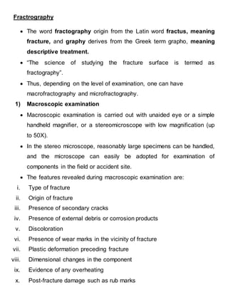
  • 2. Example: Macrofractography of ductile tensile sample: A ductile tensile fracture in a component of circular cross section consists of three distinct zones as shown in the figure. 1. The inner flat/fibrous zone with a fibrous appearance is where the fracture starts and grows slowly. 2. The fracture propagates fast along the intermediate radial zone. The radial lines extended backward point to the fracture origin. Sometimes the radial lines start from the origin itself. 3. The fracture finally terminates at the shear lip zone that is the annular region near the periphery of the fracture surface. The shear lip zone is at an angle of 45° to the tensile stress direction.
  • 3. Fig. 166 "Cup and cone" tensile fracture of cylindrical test specimen is typical for ductile metals; annealed AISI 1035. Fracture originates near the center of the section with multiple cracks that join and spread outward. When cracks reaches a region near the surface, the stress state changes from tension to macro shear, forming a fracture at approximately 45° to the plane of the major fracture--the familiar "shear lip." (D.J. Wulpi, Consultant) Example: Macrofractography of Brittle sample: Figure: Fast, unstable crack propagation may sometimes be manifested as a series of chevron marks on the fracture surface
  • 4. Example: Four fatigue-fracture surfaces that were produced in bending in the laboratory with the use of assorted notches to simulate service conditions; the material is AISI W1 tool steel. All at 2×  The specimen in Fig. 760, which was tested without a notch and fractured after 432,000 cycles at 365 MPa (53 ksi), shows two cracks origins at opposite corners where bending was maximum.  The specimen in Fig. 761 had a single notch at top and broke after 20,500 cycles at 434 MPa (63 ksi); note the small shear lip around the region of fast fracture at bottom.  The specimen in Fig. 762 was notched at two corners that were along an axis not in the plane of bending and broke after 50,000 cycles at 338 MPa (49 ksi); the two resulting fatigue cracks therefore had somewhat distorted shapes.  The specimen in Fig. 763 was notched at four sites--two in the bending plane and two in a plane 60° from it--and broke after 10,260 cycles at 434 MPa (63 ksi). The four notches produced fatigue zones, which formed two major crack fronts that nearly penetrated the section.
  • 5. 2) Microscopic Examination / Microfractography  The information thus gathered at the macroscopic level has to be integrated with the observations on detailed examination at the microscopic level so that meaningful conclusions can be drawn regarding the cause of failure.  Microscopic examination is carried out using optical microscopes and electron microscopes, the choice dictated by the magnification and resolution desired.  Microscopic examination is carried out on the fracture surface to study the fracture features and also on a section transverse to the fracture surface to study the internal structure of the material.  The latter is a destructive test and should be carried out only at the end after recording all the microfractographic features.  The additional information one can obtain through microscopy includes:  Microstructure of the material through metallography  Path of fracture  Mode of fracture  Length of the crack that pre-existed and propagated by fatigue  Length of the fatigue crack before it became critical  Presence of inclusions, pits, or other flaws at the origin  Striation spacing of the fatigue crack  Presence of corrosion products
  • 6.  The fracture surfaces are generally rough and cannot be easily studied entirely by an optical microscope because of its limited depth of focus and resolution.  For microfractography, instruments with better depth of focus and resolution are necessary. These requirements are met by the electron microscope of which there are two types: The scanning electron microscope (SEM) The transmission electron microscope (TEM)
  • 7. Possible combinations of mating dimple shapes resulting from different stress states, which cause the crack tip to deform by various modes
  • 8. Example-1 SEM Fractograph Elongated and equexed dimples:
  • 9. Example-2 TEM Fractograph Elongated and equexed dimples:
  • 10. Example 3: Fig. 17 Surface of tensile-test fracture in specimen of low-carbon, high- oxygen iron that was broken at room temperature. Many of the equiaxed dimples contain spheroidal particles of FeO. The rectangle marks the area shown at higher magnification in Fig. 18 and 19. SEM, 500× Fig. 18 Enlargement of the area within the rectangle in Fig. 17, showing the surface contours of the dimple cavities of the very ductile fracture. Dimly visible in the central dimple is a globular particle of FeO; the particle is shown more clearly in Fig. 19. SEM, 2400×
  • 11. Example-4: Stereo pair of scanning electron microscope fractographs of the surface of a tensile-test fracture obtained at room temperature The alloy was a low-carbon iron to which an appreciable amount of Fe2O3 had been added to form an aggregate of FeO inclusions. The dimples that are characteristics of ductile rupture are evident here, and many of these dimples contain one or more globular oxide inclusions that are readily apparent. There appear to be two sizes of these oxide inclusions--some being about 6 μm in diameter and other about 3 μm in diameter. Unlike many inclusions displayed in other fractographs, which have relatively smooth, unbroken contours several of the particles shown here possess sizable surface defects. Some of these defects may be exposed internal shrinkage cavities. The surfaces of the dimples show contours that vaguely resemble fatigue-striation marks. The differences in topographic contours of the dimples displayed in this stereo pair of fractographs can be appreciated by viewing the fractographs stereographically, which provides a three dimensional effect. It then becomes apparent that the dimples are chimney like cavities with nearly vertical walls in many instances and with bottoms at great depth that appear black and without detail. The FeO inclusions appear to cling to the cavity walls, many at a point part way to the bottom of the "chimney." Most of the separating walls between adjacent chimneys are extremely thin, which makes it surprising that these walls did not rupture at a point closer to the bottom of the chimney. 1200×
  • 12. Example- 5: Sequence of SEM fractographs: Sequence of SEM fractographs, at increasing magnifications (80×, 950×, and 5000×, respectively), that show a fracture in an iron alloy containing 0.14% S and 0.04% O. The fracture was obtained by bending at room temperature. Several spheroidal oxide inclusions are visible, most of them having diameters in the range of 1 to 3 μm. The rectangle in Fig. 6 indicates the area that is shown at higher magnification in Fig. 7, and the rectangle in Fig. 7 indicates the area that is shown at still higher magnification in Fig. 8. The 6-μm-diam oxysulfide particle in Fig. 8 shows a shrinkage cavity plus a white spot from an electron beam impingement in fluorescent x-ray analysis. It is quite evident that, during the process of microvoid coalescence, the iron matrix has become detached from the globular inclusions at the metal-to- oxide and metal-to-sulfide interfaces, leaving these inclusions unaffected by the applied stresses and severe deformation taking place around them.
  • 14. Example- 7: Sequence of SEM fractographs: Fig. 14 Intergranular fracture that was generated in a specimen of oxygen- embrittled Armco iron by a Charpy impact test at room temperature. The grain features appear sharp and clean. Note the secondary cracks, which follow grain boundaries. See also Fig. 15 and 16 for views of other regions of this fracture. SEM, 55× Fig. 15 View of another region of the surface of the impact fracture shown in Fig. 14, showing facets that resulted from a combination of intergranular rupture and transcrystalline cleavage. Note the array of small river patterns at the bottom edge of the large facet at center. See also Fig. 16. SEM, 655× Fig. 16 View of a third region of the surface of the impact fracture shown in Fig. 14 and 15. Note the almost perfect grain-boundary surfaces and the sharp edges and points at which the separated-grain facets meet. The secondary cracks are equally clean separations. SEM, 670×
  • 15. Example-8: Fracture of SiC initiated at corrosion pits. The boron- and carbon-doped SiC was injection molded and pressure less sintered. The sample was then coated with 2 mg/cm2 (0.07 oz/ft2) Na2SO4 and exposed for 48 hat 1000 °C (1830 °F) in 0.1% SO2/O2 gas. Corrosion products were removed with a solution of 10% HF inwater and the sample was broken in four-point bending at a strain rate of 0.5 mm/min (0.02 in./min). Fig. 1278: Fracture surface shows radial crack lines emanating from the origin, which was a corrosion pit (top). SEM (30° tilt), 115×. Fig. 1279: Close-up of pit-ceramic interface reveals preferential grain- boundary attack in advance of the pit. SEM (30° tilt), 4300× (J.L. Smialek and N.S. Jacobson, NASA Lewis Research Center)
  • 17. Metallography of Fracture Specimen:  The metallurgical microscope is yet another instrument very useful to the failure analyst.  After collecting all the information through fractography of the failed component, a section of the component can be cut transverse to the fracture surface.  This section is then polished and examined in the metallurgical microscope, both before and after etching. Inclusions present in the material are observed on the as-polished surface.  The inclusion rating can be determined by standard quantitative microscopy techniques.  By differences in color, reflectivity, and refractive index, they can also be identified with some prior experience.  The polished specimen is then etched with suitable etchants to reveal the microstructure of the material.  Abnormalities in the microstructure that may have been responsible for the failure can be identified at this stage.  The path of a crack, whether it is intergranular or transgranular, and branched or not branched, will be clear in the microstructure.  Cracks due to stress corrosion, hydrogen embrittlement, and liquid metal embrittlement are generally intergranular with some exceptional situations.  Fatigue cracks are transgranular. If a stress-corrosion crack propagates by fatigue, the transition from intergranular to transgranular mode can be seen in the microstructure.
  • 18.  Stress-corrosion cracks in certain stainless steels are transgranular with extensive branching.  Plastic deformation of the component prior to fracture can be recognized in the microstructure by the elongated grains.  Abnormal grain growth, segregation of brittle or weak phases at the grain boundaries, and recrystallization are some of the other features that can be identified by metallography.  Figure shows the intergranular and transgranular modes of crack propagation, revealed by metallography. Figure: Optical microstructure showing transgranular crack propagation
  • 19. Figure: Optical microstructure showing intergranular crack propagation.