1. Abstract
Dynamic performance investigation of Wind Turbine (WT) implementing Permanent Magnet Synchronous Generator
(PMSG) under variable wind speeds and load circumstances are investigated in this paper. The injected active and reactive
power respectively regulate by d-axis current and q-axis current using active and reactive power (P-Q) control method. The
P-Q controller can adjust DC link voltage, active and reactive power. The generated reactive power via the WT is adjusted at
zero so that the Power Factor (PF) is retained unity. The proposed system is containing of WT, PMSG, rectifier, a DC bus by
capacitor and voltage source inverter. The simulation results depict the accuracy and credibility of the WT and the strategy
of inverter controller. The thorough Wind Power Generation System (WPGS) and power electronic converters interfaces
are proposed by using Matlab/Simulink.
Dynamic Analysis of PMSG Wind Turbine under
Variable Wind Speeds and Load Conditions in
the Grid Connected Mode
Maziar Izadbakhsh1*
, Alireza Rezvani1
, Majid Gandomkar2
and Sohrab Mirsaeidi1
1
Young Researchers and Elite Club, Saveh Branch, Islamic Azad University, Saveh, Iran; m.izadbakhsh@iau-saveh.ac.ir
2
Department of Electrical Engineering, Saveh Branch, Islamic Azad University, Saveh, Iran
Keywords: Dynamic Analysis, Load Circumstances, PMSG, P-Q Controller, Wind Turbine (WT)
1. Introduction
In last decade, miscellaneous technologies of renewable
energy such as Wind Power Generation System (WPGS),
Photovoltaic Systems (PV) and biomass have made many
impressive developments in efficiency improvement and
costs continue to come down. As regards to less power
and efficiency in PV system and enormous costs in com-
parison with wind system, WPGS is proposed as one of
the outstanding renewable energy sources1,2
. Amongst the
synchronous and asynchronous generators, Permanent
Magnet Synchronous Generator (PMSG) is more favor-
able because of self-excitation, lower weight, smaller size,
less maintenance cost and the elimination of gearbox have
high efficiency and high PF comparing to WRSG, SCIG,
DFIG etc. Permanent magnet generators do not require
a supplementary supply for magnetic field excitation or
slip rings and brushes3,4
. The major disadvantage of the
PMSG is the risk of demagnetization caused by too high
temperatures or high currents. There are two modes for
inverter operating: 1. Active and reactive control mode
(P-Q Control) and 2. Voltage and frequency control mode
(V-F control)5–8
.
The analysis responses of WT based PMSG under
variable wind speeds and load circumstances and have
been studied. The P-Q control strategy is taken from park
transformation and is simulated by Simulink/Matlab.
This paper consists of part (2) system where topology
is illustrated. In part (3) the major equipment of system
are described that include: wind turbine, PMSG genera-
tor, P-Q control strategy. Simulation results and analysis
are shown in part (4). Finally the conclusions based on
present studies are presented in part (5).
2. System Configuration
In Figure 1, the diagram of a wind energy system based on
PMSG connected to network is demonstrated. The DC link
*Author for correspondence
Indian Journal of Science and Technology, Vol 8(14), 51864, July 2015
ISSN (Print) : 0974-6846
ISSN (Online) : 0974-5645
2. Dynamic Analysis of PMSG Wind Turbine under Variable Wind Speeds and Load Conditions in the Grid Connected Mode
Indian Journal of Science and Technology2 Vol 8 (14) | July 2015 | www.indjst.org
voltage is regulated by PI controller till it reaches a rated
value and then this fixed voltage is converted to AC voltage
applying inverter. The inverter adjusts the DC link volt-
age and moreover, reactive and active power is injected via
q-axis and d-axis respectively, using P-Q control method.
3. System Modeling
3.1 Power of Wind Turbine
The wind power is computed as following equation9,10
:
P AC Vp w= 0 5 3
. ,( )r l b (1)
Where, P = power, r = density of air, A = wind turbine
rotor swept area, Vw
= speed of wind in m/sec, Cp
is the
aerodynamic efficiency of rotor. The ratio of tip speed (λ),
determined as the the linear speed ratio and is given by
following equation7–12
:
λ =
Wm
w
R
V
(2)
Wm
= Speed of rotor in rad/s and R: turbine radius
Cp( ), . .λ β λ
= − −
−
0 5176
116
0 4 5
21
l
b
i
e i
(3)
λi =
+
−
+
−
1
l b b0 08
0 035
13
1
.
.
(4)
Furthermore, the Cp
is depending on the blade pitch
angle and TSR. The generic change of Cp
based on TSR for
different values of (β) is illustrated in Figure 2.
3.2 PMSG Modeling
The equations of PMSG voltage are defined by9
:
di
dt
ds
= ω
1
Ld
− − +
V R i L ids s ds q qs
(5)
di
dt L
V R i L i
qs
q
qs s qs d ds m= − − − +
1
ω ωφ (6)
Where Vds
and Vqs
are q and d axis machine voltages and
Ids
and Iqs
are q and d axis machine currents, respectively.
Rs
: Resistance of Stator, W: frequency of electrical angular,
Ld
: inductance of d-axis, Lq
: q axis inductance, ϕm
: flux
linkage amplitude. If rotor is cylindrical (Ld ≈
≈ Lq
= Ls
),
the equations of electromagnetic torque are presented as
following:
Te =
3
2
p im qsf (7)
Which p is the PMSG pole pair’s number.
3.3 P-Q Control Strategy
The rectifier determined AC to DC and then, DC link
voltage applying PI controller to get fixed value, then DC
Voltage is converted to obtain favorable AC voltage11
.
P = +
3
2
( )V I V Igd d gq q (8)
Q = −
3
2
( )V I V Igq d gd q (9)
In Figure 3, the synchronous reference will compute
amount of d axis, q axis and zero sequels in two axis
rotational reference vector for three phases is depicted.
For this, we use equations (12) and (13).
V
V
V
V
V
V
i
i
i
C
i
i
i
d
q
0
a
b
c
d
q
a
bC
=
=,
0 cc
(10)
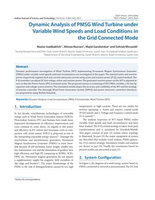
Figure 1. The block diagram of system.
Figure 2. Cp
vs λ for various pitch angles (β).
3. Maziar Izadbakhsh, Alireza Rezvani, Majid Gandomkar and Sohrab Mirsaeidi
Indian Journal of Science and Technology 3Vol 8 (14) | July 2015 | www.indjst.org
Cdq0
2
3
2
3
2
3
2
3
2
3
=
− +
− − − − +
cos cos( ) cos( )
sin sin( ) sin( )
θ θ π θ π
θ θ π θ π
11
2
1
2
1
2
(11)
In Figure 4, model of converter controller is
demonstrated. One of the most significant specifications
of P-Q control is the ability of autonomous performance
of network. The loop capacitor voltage control is applied
to locate reference current for d-axis for controlling active
power . The q-axis reference current is assigned to output
reactive power11,12
. If PF is unit, hence this current is
zero13–16
.
4. Simulation Results
Simulation results under various circumstances are
presented by implementing Matlab. The block diagram is
demonstrated in Figure 5. The grid voltage and frequency
were 480 V and 60 Hz, respectively. The PMSG parameters
as follows: resistance of stator: 2.9 Ω, inertia: 0.9e–3
kg-m2
,
torque constant: 12N-M/A, Pole pairs: 8, power: 95kW,
Nominal speed: 12 m/s, Ld
= Lq
= 9 mH. Alternative
parameters, DC link Capacitor: 5500µF, DC link voltage:
1150 V.
4.1 Case Study 1
The aim of this case is dynamic analysis of grid connected
PMSG wind turbine in state of fixed load and variable
wind speed. In this case, speed of wind, during 0 t 4
sec is 11 m/sec and in t = 4 s is declined to 9 m/s and
load is the constant 110 kW. Active powers are shown in
Figure 6.
According to reduction of wind speed, the turbine
torque decrease and based on this active power output
from wind system the inverter current declines. Power
shortage is fed by network. The DC link voltage remained
at a fixed value (1150V) and in Figure 7, the effectiveness
of the appointed controller as demonstrated.
Turbine output power is depicted in Figure 8, which is
decreased to 79 kW in t = 4.
In Figure 9, inverter output current is shown. One
of the most significant aspects of applying DGs and
connecting them to network is maintenance the THD at
the least value. The THD should be around 5%, due to
IEEE Std.1547.2003.
Figure 3. Synchronous Reference Machine.
Figure 4. Modeling of inverter controller.
Figure 5. The block diagram of system in MATLAB/
SIMULINK.
4. Dynamic Analysis of PMSG Wind Turbine under Variable Wind Speeds and Load Conditions in the Grid Connected Mode
Indian Journal of Science and Technology4 Vol 8 (14) | July 2015 | www.indjst.org
In Figure 10, the THD curve was demonstrated
around 5% to 6.5%.
According to reduction of wind speed, the turbine
torque decrease and based on this active power output
from wind system and inverter current declined.
4.2 Case Study 2
The aim of this case is dynamic analysis of grid connected
PMSG wind turbine in state of variable load and fixed
wind speed. In this case, during 0 t 4 sec load is 110
kW and in t = 4, it has 40% step increase in load and
also, wind speed is 11 m/s. The active powers shown in
Figure 11, which is depicted the imported power by grid
to supply the load.
Grid current is illustrated in Figure 12.
It’sbeenobviousthatturbineoutputpowerisinvariant,
because of fixed wind speed which is shown in Figure 13.
Figure 14 is depicted the inverter output current.
Figure 6. Active powers.
Figure 7. The DC link voltage.
Figure 8. Turbine output power.
Figure 9. Inverter output current.
Figure 10. THD %.
Figure 11. Active powers.
5. Maziar Izadbakhsh, Alireza Rezvani, Majid Gandomkar and Sohrab Mirsaeidi
Indian Journal of Science and Technology 5Vol 8 (14) | July 2015 | www.indjst.org
Figure 18. Grid current.
Figure 12. Grid current.
Figure 13. Turbine output power.
Figure 14. Inverter output current.
Figure 15. Reactive power.
Figure 16. Active powers.
Figure 17. Inverter output current.
The generated reactive power by the wind turbine was
adjustedatzerowhichthePFkeptupunityasdemonstrated
in Figure 15. Wind turbine by applying appropriate
controller could meet the load demand assuredly.
4.3 Case Study 3
The aim of this case is dynamic analysis of grid connected
PMSG wind turbine in state of variable load and variable
wind speed. In this case, during 0 t 5 sec the load
power is 110 kW and in t = 5, it has %55 step increase in
load. Also wind speed is 11 m/s which in t = 3 reduced
to 9 m/s. Figures (16–20) show the simulation results
for active powers, inverter output current, grid current,
turbine output torque and inverter output voltage. It’s
6. Dynamic Analysis of PMSG Wind Turbine under Variable Wind Speeds and Load Conditions in the Grid Connected Mode
Indian Journal of Science and Technology6 Vol 8 (14) | July 2015 | www.indjst.org
been clear that grid with cooperation of wind system by
applying PQ controller can easily meet the load demand.
5. Conclusion
The presented study is a modeling and dynamic analysis
of grid connected permanent magnet synchronous
generator using Matlab/Simulink software under load
circumstances and variable wind speed. Modeling of
DC/AC grid connected inverter is proposed. The con-
verter adjusts the DC link voltage and also, active power
and reactive power are injected by d-axis and q-axis
respectively, using P-Q control method. The reactive
generative power turbine is located at zero value and PF
is kept at unity. The simulation result in presented model
is satisfactory.
6. References
1. Izadbakhsh M, Gandomkar M, Rezvani A, Ahmadi A.
Short-term resource scheduling of a renewable energy
based micro grid. Renew Energ. 2015; 75:598-06.
2. Rezvani A, Gandomkar M, Izadbakhsh M, Ahmadi A.
Environmental/economic scheduling of a micro-grid with
renewable energy resources. Journal of Cleaner Production.
2015; 87:216–26.
3. Izadbakhsh M, Rezvani A, Gandomkar M. Improvement of
microgrid dynamic performance under fault circumstances
using ANFIS for fast varying solar radiation and fuzzy
logic controller for wind system. Arch Electr Eng. 2014;
63(4):551–78.
4. IzadbakhshM,RezvaniA,GandomkarM.Dynamicresponse
improvement of hybrid system by implementing ANN-GA
for fast variation of photovoltaic irradiation and FLC for
wind turbine. Arch Electr Eng. 2015; 64(2):291–14.
5. Carrasco JM, Garcia-Franquelo L, Bialasiewicz JT, Galvan
E, Portillo RC, Martin MA, Leon JI, Mereno N. Power
electronic systems for the grid integration of renew-
able energy sources: A Survey. IEEE Trans on Industrial
Electronics. 2006; 53(4):1002–16.
6. Yuan LK, Chen Y, Chang Y. MPPT battery charger for
stand-alone wind power system. IEEE Trans Power
Electron. 2011; 26(6):1631–38.
7. Senjyu T, Sakamoto R, Urasaki N, Funabashi T, Sekine H.
Output power leveling of wind farm using pitch angle con-
trol with fuzzy neural network. IEEE Power Engineering
Society General Meeting. 2008; 36(10):1048–66.
8. Gaurav N, Kaur A. Performance evaluation of fuzzy
logic and PID controller by using MATLAB/Simulink.
International Journal of Innovative Technology and
Exploring Engineering (IJITEE). 2012; 1(1):84–8.
9. Md. Arifujjaman. Modeling, simulation and control of grid
connected Permanent Magnet Generator (PMG)-based
small wind energy conversion system. IEEE Electrical
Power and Energy Conference; 2010. p. 1–6.
10. Yao X, Guo Ch, Xing Z, Li Y, Liu Sh. Variable speed wind
turbine maximum power extraction based on fuzzy logic
control. IEEE International Conference on Intelligent
Human-Machine Systems and Cybernetics; 2009. p. 202–5.
11. Uehara A, Pratap A, Goya T, Senjyu T, Yona A, Urasaki
N, Funabashi T. A coordinated control method to smooth
wind power fluctuations of a PMSG-based WECS. IEEE
Trans Energ Convers. 2011; 26(2):550–8.
12. Najafi M, Siahi M, Ebrahimi R, Hoseynpoor M. A new
method to control of variable speed wind generation
system connected to permanent magnet synchronous gener-
ator. Australian Journal of Basic and Applied Sciences. 2011;
5(5):433–40.
13. RolanA,LunaA,VazquezG,AguilarD,AzevedoG.Modeling
of a variable speed wind turbine with a permanent magnet
synchronous generator. IEEE International Symposium on
Industrial Electronics (ISlE 2009); 2009. p. 734–9.
14. Zareen N, Mustafa MW. Real-time energy imbalance
management scheme for electric vehicles in the smart
Figure 19. Turbine output torque
Figure 20. Inverter output voltage.
7. Maziar Izadbakhsh, Alireza Rezvani, Majid Gandomkar and Sohrab Mirsaeidi
Indian Journal of Science and Technology 7Vol 8 (14) | July 2015 | www.indjst.org
grid. Indian Journal of Science and Technology. 2015 Feb;
8(3):170–81.
15. Gheydi M, Effatnejad R, Ramezanpour P. Evaluation of
uncertainty in hybrid plants, including wind turbine, pho-
tovoltaic, fuel cell, and battery system using fuzzy logic.
Indian Journal of Science and Technology. 2014 Feb;
7(2):113–22.
16. Sadeghi M, Gholami M. Fuzzy logic approach in controlling
thegridinteractiveinvertersofwindturbines.IndianJournal
of Science and Technology. 2014 Aug; 7(8):1196–200.